1
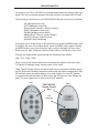
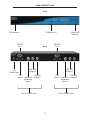
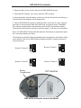
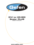
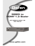
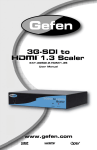
®
DVI to HD-SDI
Pro Scaler
EXT-DVI-2-HDSDIPRO
www.gefen.com
ASKING FOR ASSISTANCE
Technical Support:
Telephone
Fax
(818) 772-9100
(800) 545-6900
(818) 772-9120
Technical Support Hours:
8:00 AM to 5:00 PM Monday through Friday Pacific Time
Write To:
Gefen Inc.
C/O Customer Service
20600 Nordhoff Street
Chatsworth, CA 91311
www.gefen.com
[email protected]
Notice
Gefen, LLC reserves the right to make changes in the hardware, packaging, and
any accompanying documentation without prior written notice.
The DVI to HDSDI PRO is a trademark of Gefen LLC
All trademarks are the property of their respective owners.
© 2011 Gefen, LLC. All rights reserved.
All trademarks are the property of their respective companies.
Rev A3
TABLE OF CONTENTS
1
Introduction
2
Operation Notes
3
Panel Descriptions
4
Menu Functions
6
Supported Input/Output Resolutions
7
RMT-8HDS-IR Installation
8
RS-232 Control and Firmware Update Procedure
9
Specifications
10
Warranty
INTRODUCTION
The Gefen DVI to HDSDI Pro Scaler combines two of our DVI to HDSDI Scaler
Plus units into one rack-mountable unit. It still incorporates full single-link DVI-D
conversion scaled to your choice of SD/HDSDI Single- or Dual-link modes, but now
simplifies your rack. Resolutions of up to 1080p are supported over the HDSDI link
for those that want true “High Definition.” Performance has been greatly enhanced
due to Gennum’s VXP Scaler circuitry onboard, allowing for new features such as
Genlock, Color & Gamma Correction, Noise Reduction, Detail Enhancement, Aspect
Ratio Selection, Pattern Generator Mode, and Multiple Language Menu Support.
Bottom Line? More performance, less cost.
HOW IT WORKS
DVI devices are connected to the DVI inputs and SDI devices are connected to the
SDI outputs. When the source, display and the Scaler are powered and connected,
video signals are converted to the proper format. There are two separate menu
systems for each integrated DVI to HDSDI box. Input 1 is labeled as the Master
device in the menu system while Input 2 is labeled as the Slave device. Please refer
to page 2 on how to access each separate menu system
CONTENTS
The DVI to HD-SDI Pro consists of:
(1) DVI to HDSDI Pro Scaler unit
(2) 6 foot DVI Cable (m-m)
(1) DB-9 Cable
(1) RMT-8HDS-IR Remote Control
(1) Rack Ears
(1) 5V Universal DC Power Supply
(1) User Manual
1
OPERATION NOTES
On power up, the DVI to HD-SDI Pro will automatically detect the format of the input
signal. The unit is controlled using the included remote or through the RS-232 port.
The following are the buttons for the RMT-8HDS-IR Remote Control Unit (included):
- UP (Navigates cursor up)
- LEFT (Navigates cursor left)
- Enter (Accept Operation / Return to Menu)
- RIGHT (Navigates cursor right)
- DOWN (Navigates cursor down)
- MENU (Show / Hide On screen Display)
- OUTPUT (Change Output Format)
- SOURCE (Non operational)
To bring up the on screen menu for the master device, press the MENU button once.
To bring up the menu for the slave device, press the MENU button again. Pressing
the MENU button once more will exit the menu system. Navigation is done using
Buttons up, left, right, and down; Push the Enter button to accept the cursor focus.
Pressing the Output button cycles through the following output modes:
480i - 576i - 720p - 1080i
Other functions and output modes can be accessed through the on screen menu.
To Restore I/O settings, simply recycle power on the Scaler
*Note: The IR Remote Control Unit has a small bank of adjustment switches known
as DIP (Dual Inline Package) switches located inside the battery compartment. Both
DIP switches under the remote battery cover must initially be in the OFF position
to communicate with the Scaler, as they control the IR frequency used. Please see
page 7 for more information on how to set the DIP switches.
Front
RMT-8HDS-IR
Remote Control
Unit
DIP
switches
2
Back
PANEL DESCRIPTIONS
Front
IR Receiver 1
IR Receiver 2
RS-232
Port 1
5V
Power Input
Back
HD-SDI
Output 1
Power LED
Indicator
RS-232
Port 2
HD-SDI
Output 1
DVI
HD-SDI
GenLock
Input 1
Output 2
Reference
Input 1
DVI
HD-SDI
GenLock
Input 2
Output 2
Reference
Input 2
DVI to HDSDI Unit 1
DVI to HDSDI Unit 2
3
Menu Functions
Aspect:
-Full Screen: Stretches input to fill the Monitor.
-Letter / Pillar Box:
Sets the aspect ratio to fit a letter or pillar box format.
-Panoramic: Panoramic Zoom feature
-Extract: Feature to magnify the signal.
-Extract Size: Adjusts signal magnification.
-Horizontal / Vertical Position: Moves the magnified signal
Horizontally and Vertically
-Through: Feature to crop the signal.
-Horizontal / Vertical Size:
Horizontally and Vertically contracts
or expands the cropping viewport.
-Horizontal / Vertical Position: Move the signal Horizontally or
Vertically inside the cropping viewport.
Layout:
-Size and Position:
-Horizontal / Vertical Size: Adjust Horizontal or Vertical
resolution.
-Horizontal / Vertical Position: Move image Horizontally or
Vertically.
Picture:
-Image Color:
-Contrast: Individually adjust the contrast for red, green and blue
-Brightness: Individually adjust the brightness for red, green and
blue
-Black level: Adjust black levels between 0 (default) and 100
-Detail Enhancement:
-Detail Enhancement: Digitally enhance signal
-Noise Threshold: Adjusts noise allowed in detail enhancement
-Noise Reduction: Digitally reduce signal noise
-Motion Threshold
4
Menu Functions (continued...)
Input:
-Input Video Format: Auto Detect by default. Signal can be forced to a specific
High-definition resolution. (Please see Supported Input/Output Resolutions for
more information).
-Input Graphic Format: Auto Detect by default. Signal can be forced to a
specific computer resolution. (Please see Supported Input/Output Resolutions
for more information).
-Clean Aperture:
-Horizontal and Vertical Size: Stretch image Horizontally or Vertically
-Horizontal and Vertical Position: Move image in view port Horizontally
or Vertically
-Non-standard sync
-Remote Channel: Changes the IR code of the DVI to HDSDI Scaler to one of 4
different settings between 0 and 3. When the remote channel is changed, dip
switches in the remote must be changed to the corresponding code in
order to continue operating the DVI to HDSDI Scaler.
(Please see RMT-8HDS-IR Installation page for more information.)
Output:
-Output Format: Select the desired output resolution. (Please see Supported
Input/Output Resolutions for more information).
-Link Configuration
-Genlock Reference: Locks input clock in sync with output clock. 2 locking
methods by either the DVI input or the Reference input.
(Note: feature only works if input and output frequencies are multiples of each
other)
-Language: Set menu to display English or French text.
-Gamma Correction:
-Default: Set for Default Gamma settings.
-sRGB
-Custom: Enables Gamma Coefficient menu item as the current
Gamma coefficient.
-Gamma Coefficient: (0.3 - 3.0); Default set at 1.0.
Patterns:
-Color Bars: Display color bar video pattern.
-Cross Hatch: Display cross hatch video pattern.
General:
-Save configuration
-Restore default configuration
5
SUPPORTED INPUT/OUTPUT RESOLUTIONS
Input Video Formats Supported:
480i
10305i/59.94
480p
1035i/60
576i
1080i/50
576p
1080i/50M
720p/23.98
1080i/59.94
720p/24
1080i/60
720p/25
1080p/23.98
720p/29.97
1080p/24
720p/30
1080p/25
720p/50
1080p/29.97
720p/59.94
1080p/30
720p/60
1080p/50
1080p/50M
1080p/59.94
1080p/60
1080sf/23.98
1080sf/24
1080sf/25
1080sf/29.97
1080sf/30
2K-p/23.98
2K-p/24
2K-sf/23.98
2K-sf/24
Input Graphic Format Supported:
640x350/85
1024x768/85
640x400/85
1280x854
640x480/60
1152x864/75
640x480/75
1280x768/60
640x480/85
1280x960/60
800x600/60
1280x960/85
800x600/75
1280x1024/60
800x600/85
1280x1024/75
1024x768/60
1280x1024/85
1024x768/75
1360x768/60
1366x768/60
1366x923/50
1440x900/60
1440x1080/60
1440x1080/60
1600x1024
1600x1200/60
1680x1050/60
1920x1200/60
2048x1080
Output video formats supported:
480i
10305i/59.94
480p
1035i/60
576i
1080i/50
576p
1080i/50M
720p/23.98
1080i/59.94
720p/24
1080i/60
720p/25
1080p/23.98
720p/29.97
1080p/24
720p/30
1080p/25
720p/50
1080p/29.97
720p/59.94
1080p/30
720p/60
1080p/50
1080p/50M
1080p/59.94
1080p/60
1080sf/23.98
1080sf/24
1080sf/25
1080sf/29.97
1080sf/30
2K-p/23.98
2K-p/24
2K-sf/23.98
2K-sf/24
6
RMT-8HDS-IR Installation
1. Remove battery cover from the back of the RMT-8HDS-IR remote.
2. Verify that DIP switches 1 & 2 are in the down (OFF) position.
3. Insert the battery, hold the battery so that you can see the positive side facing up.
The side that is not marked must be facing down.
4. Test the RMT-8HDS-IR remote by pressing ONLY one button at a time. The indicator light on the remote will flash once each time you press a button. WARNING:
Do not press multiple buttons simultaneously and do NOT press buttons rapidly.
These actions will cause the remote to reset and steps 1-4 will have to be repeated.
Note: The RMT-8HDS-IR ships with two batteries. One battery is required for operation, the second battery is a spare.
The following are the DIP switch combinations that correspond to the Remote Code
menu option on the DVI to HDSDI Scaler (Please see Menu Functions section for
more information):
Remote Channel 1:
Remote Channel 0:
1
2
1
2
1
2
Remote Channel 3:
Remote Channel 2:
1
2
Battery
Compartment
DIP Switches
RMT-8HDS-IR Remote Control Unit (Back)
7
RS-232 CONTROL
The DVI to HD-SDI Pro can be controlled via the RS-232 port on the rear of the unit.
Please refer to the Communication Protocol for Gennum VXP Products on Gefen’s
website at: http://www.gefen.com/kvm/support/download.jsp.
FIRMWARE UPDATE PROCEDURE
1
Connect your computer’s RS-232 (serial) port to the RS-232 port on the
DVI to HD-SDI Scaler Pro using a male to female, straight pin-to-pin
RS-232 cable. Do not use a null modem cable.
2
Please download the latest firmware from Gefen’s website at:
http://www.gefen.com/kvm/support/download.jsp
3
Open and edit the setup.bat file and on the line “set comport=” edit the port
number to match your comport number.
4
Run the setup.bat batch file and follow the instructions
8
SPECIFICATIONS
Input Video Bandwidth............................................................................. 2 x 165 MHz
Output Video Bandwidth...........................................................................4 x 165 MHz
Maximum Input Resolution..........................................................................2048x1080
Maximum Output Resolution.................................................................2048x1080p24
DVI Connector...........................................................DVI-I 29 pin female (digital only)
SDI/HDSDI Connector...............................................................................BNC female
Data Port................................................................................................Serial RS-232
Power Supply................................................................................................5V 8A DC
Power Consumption.............................................................................20 watts (Max.)
Dimensions..................................................................................6.5”W x 1”H x 6.75”H
Shipping Weight...................................................................................................5 lbs.
9
WARRANTY
Gefen warrants the equipment it manufactures to be free from defects in material
and workmanship.
If equipment fails because of such defects and Gefen is notified within two (2)
years from the date of shipment, Gefen will, at its option, repair or replace the
equipment, provided that the equipment has not been subjected to mechanical,
electrical, or other abuse or modifications. Equipment that fails under conditions
other than those covered will be repaired at the current price of parts and labor in
effect at the time of repair. Such repairs are warranted for ninety (90) days from
the day of reshipment to the Buyer.
This warranty is in lieu of all other warranties expressed or implied, including
without limitation, any implied warranty or merchantability or fitness for any
particular purpose, all of which are expressly disclaimed.
1.
Proof of sale may be required in order to claim warranty.
2.
Customers outside the US are responsible for shipping charges to and from
Gefen.
3.
Copper cables are limited to a 30 day warranty and cables must be in their
original condition.
The information in this manual has been carefully checked and is believed to
be accurate. However, Gefen assumes no responsibility for any inaccuracies
that may be contained in this manual. In no event will Gefen be liable for
direct, indirect, special, incidental, or consequential damages resulting from
any defect or omission in this manual, even if advised of the possibility of such
damages. The technical information contained herein regarding the features and
specifications is subject to change without notice.
For the latest warranty coverage information, refer to the Warranty and Return
Policy under the Support section of the Gefen Web site at www.gefen.com.
PRODUCT REGISTRATION
Please register your product online by visiting the Register Product page
under the Support section of the Gefen Web site.
10
Rev A3
20600 Nordhoff St., Chatsworth CA 91311
1-800-545-6900
818-772-9100
www.gefen.com
Pb
This product uses UL listed power supplies.
fax: 818-772-9120
[email protected]