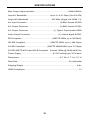
1
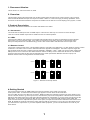
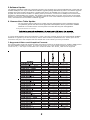
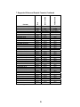
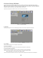
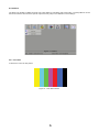
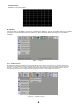
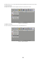
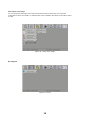
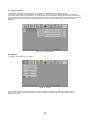
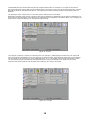
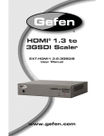
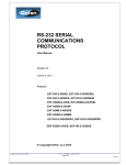
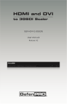
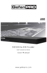
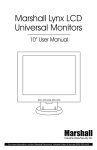
3G-SDI to
1.3 Scaler
EXT-3GSDI-2-HDMI1.3S
EXT
3G
User Manual
www.gefen.com
f
ASKING FOR ASSISTANCE
Technical Support:
Telephone
(818) 772-9100
(800) 545-6900
Fax
(818) 772-9120
Technical Support Hours:
8:00 AM to 5:00 PM Monday thru Friday PST (Pacific Standard Time).
Write To:
Gefen Inc.
c/o Customer Service
20600 Nordhoff St
Chatsworth, CA 91311
www.gefen.com
[email protected]
Notice
Gefen Inc. reserves the right to make changes in the hardware, packaging and
any accompanying documentation without prior written notice.
3G-SDI to HDMI 1.3 Scaler is a trademark of Gefen Inc.
© 2009 Gefen Inc., All Rights Reserved
All trademarks are the property of their respective companies
Rev X6
Table of contents
1. Document Version..................................................................................................................................1
2. Overview................................................................................................................................................1
3. Product Description...............................................................................................................................1
3.1 Connectors......................................................................................................................................1
3.2 LEDs................................................................................................................................................1
3.3 Remote Control..............................................................................................................................1
4. Getting Started........................................................................................................................................1
5. Software Update....................................................................................................................................2
6. Gamma User Table Update....................................................................................................................2
7. Supported Videos and Graphics format..............................................................................................2
8. On-Screen Display (OSD) Menu...........................................................................................................4
8.1 General............................................................................................................................................4
8.1.1 Language..................................................................................................................................4
8.1.2 Save Configuration..................................................................................................................4
8.1.3 Restore default configuration.................................................................................................4
8.2 Patterns...........................................................................................................................................5
8.2.1 Color Bars................................................................................................................................5
8.2.2 Cross Hatch..............................................................................................................................6
8.3 Output..............................................................................................................................................6
8.3.1 Available Formats....................................................................................................................6
8.3.2 Video Output Format...............................................................................................................7
8.3.3 Graphic Output Format...........................................................................................................7
8.3.4 Custom Output Format............................................................................................................7
8.3.5 Link Configuration...................................................................................................................8
8.3.6 Frame Rate..............................................................................................................................8
8.3.7 Deep Color................................................................................................................................9
8.4 Input.................................................................................................................................................9
8.4.1 Input Format...........................................................................................................................10
8.4.2 Link Configuration.................................................................................................................10
8.4.3 Clean Aperture........................................................................................................................11
8.4.4 Film Mode..............................................................................................................................11
8.4.5 Audio.......................................................................................................................................12
8.4.6 Remote channel.....................................................................................................................12
8.5 Picture...........................................................................................................................................13
8.5.1 Image Color.............................................................................................................................13
8.5.2 Gamma Correction.................................................................................................................14
8.5.3 Detail Enhancement...............................................................................................................14
8.5.4 Noise Reduction.....................................................................................................................15
8.5.5 Motion Threshold...................................................................................................................15
8.5.6 Output Color Range...............................................................................................................16
8.6 Layout............................................................................................................................................16
8.6.1 Size and position....................................................................................................................17
8.7 Aspect............................................................................................................................................17
9. Troubleshooting..................................................................................................................................19
10. Appendix A: Gamma LUT file format................................................................................................20
1. Document Version
This is version 1.0, authored October 16, 2009.
2. Overview
This document presents the Gefen Dual Link 3G-SDI to HDMI Scaler and all its most common options. This Converter
takes an SDI/HD-SDI/3G-SDI input and outputs it in HDMI / HDMI 1.3. It also has image processing capabilities. In this
document we will describe all features and options accessible from the built-in on-screen display (menu) system, or OSD.
3.Product Description
This section describes the different connectors and LEDs on the scaler.
3.1 Connectors
The Scaler has two SDI inputs and one HDMI output. It also has one SDI loop-out connector for each SDI input.
There is one audio S/PDIF output and one USB connector for software updates.
3.2 LEDs
There are two LEDs on the enclosure. The Power LED indicates when the scaler is powered but it also indicates
when there is an error with the scaler. If the scaler encounters an error that it cannot fix, it will blink the power
LED (to fix that problem see Troubleshooting). There is also a blue LED to indicate whenever the input is 3G.
3.3 Remote Control
The remote control has UP, Down, Left and Right buttons to navigate in the OSD menu. An “OK” button is used to confirm
a selection. The button menu is use to make the OSD menu appear and disappear. The button output changes the
signal output format from the 4 following formats: 640x480 – 800x600 – 720p – 1080i. The source button toggles the
SDI input from A to B. There are also 2 DIP switches under the battery cover to select the IR channel. The infrared
channel must be the same as the channel selected for the scaler (see section Remote channel in input). The
different infrared channel configurations are shown below.
Figure 1 - Remote Control Dip Switch
4.Getting Started
Connect the monitor using an HDMI cable to the Dual Link output on the scaler. Connect the
scaler power cable. You should see the Gefen logo appear on screen about 30 seconds later.
Connect a SDI source on the SDI input connector. Make the OSD menu appear by pushing the menu button on the
remote. Use the remote to go in the input menu, and select the proper link configuration. If the SDI source transmits
SDI single link select single link or else select the appropriate link configuration. If you are using a single link use the
SDI input A. If you are using a dual link SDI source, make sure you connect the SDI output A to the scaler SDI
input A and the same for output B and input B. At this point, the input format should be indicated in the bottom of the
OSD. By default the scaler should use the prefer output format for the monitor, but you can force the output format
you want from the output menu. If you have separate audio equipment, you can use the S/PDIF connector to your
audio device.
1
5.Software Update
The software upgrade is made from a personal computer. The computer use must have Windows XP or Vista and one
available USB port. Use only the latest official software upgrade package distributed by Gefen. The software upgrade
package will contain a folder named driver, containing the driver to be installed on the computer. Prior to the first
upgrade, the drivers must be installed. To update, power up the device, connect the PC USB port to the device then
execute the “GefenUpdater.exe” program. The operation should take about 15 minutes. If the process is interrupted
before the end or if the “GefenUpdater.exe” indicates a failure or if one of the software components has not install at
100%, reset the device and re-start the software upgrade.
6. Gamma User Table Update
o The user gamma look-up table can be created using the GefenUpdater from the installation package.
To update the gamma user table call the application GefenUpdater with the parameters: GAMMA
FileName.csv.The file name is a csv file place in the same directory than the application.
If the picture has bars on one side,
o
that it is possible that the source does have the bar pattern integrated into the output signal.
.
To call the GefenUpdater with those parameters, create a file using notepad. Write the line GefenUpdater GAMMA
FileName.csv (replace by the true file name) in the file. Save the file as “UpdateGama.bat”. Power up the device,
connect the usb port to the computer and then double click on the .bat file you have just created.
7.Supported Video and Graphics Formats
The following table contains all supported video and graphic formats for the Gefen Dual Link 3GSDI to HDMI and for
the Gefen HDMI to 3GSDI converters. The scaler can receive any of the formats indicated as input and can
convert it to any of the output formats listed. The formats not listed in the following table are not supported
2
Video
Input
Video
Input & Output
Video
Input
Video
Input & Output
HDMI-2-3GSDIS
Mode
Format
1920x1080 24 PsF
1920x1080 23.98 P
1920x1080 23.98 PsF
2048x1080 24 P
2048x1080 24 PsF
2048x1080 23.98 P
2048x1080 23.98 PsF
640x350 85 P
640x400 85 P
640x480 60 VGA
640x480 75 VGA
640x480 85 VGA
800x600 60 SVGA
800x600 75 SVGA
800x600 85 SVGA
1024x768 60 XGA
1024x768 75 XGA
1024x768 85 XGA
1280x854
1152x864 75 P
1280x768 60 P
1280x960 60 P
1280x960 85 P
1280x1024 60 SXGA
1280x1024 75 SXGA
1280x1024 85 SXGA
1360x768 60 P
1365x768 60 P
1366x768 60 P
1366x923 50 P
1440x900 60 P
1440x1080 60 P
1600x1024
1600x1200 60 UXGA
1680x1050 60 P
1920x1200 60 P
2048x1080
3GSDI-2-HDMIS
7. Supported Video and Graphic Formats, Continued
Output
Input & Output
Output
Input & Output
Video
Input
Output
Video
Input & Output
Input & Output
Video
Input
Output
Graphic
Output
Input
Graphic
Output
Input
Graphic
Output
Input
Graphic
Output
Input
Graphic
Output
Input
Graphic
Output
Input
Graphic
Output
Input
Graphic
Output
Input
Graphic
Output
Input
Graphic
Output
Input
Graphic
Output
Input
Graphic
Output
Input
Graphic
Output
Input
Graphic
Output
Input
Graphic
Output
Input
Graphic
Output
Input
Graphic
Output
Input
Graphic
Output
Input
Graphic
Output
Input
Graphic
Output
Input
Graphic
Output
Input
Graphic
Output
Input
Graphic
Output
Input
Graphic
Output
Input
Graphic
Output
Input
Graphic
Output
Input
Graphic
Output
Input
Graphic
Output
Input
Graphic
Output
Input
Graphic
Output
Input
Table 1 - Supported Formats
3
8.On-Screen Display (OSD) Menu
To access the Dual Link 3G-SDI to HDMI scaler menu, it must be connected to a video display device using the
HDMI 1.3 connector. Push the menu button on the remote to make the on-screen display menu appear and push the
button again to make it disappear. This section presents all available options from the menu. The menu is divided in 7
categories: Aspect, Layout, Picture, Input, Output, Patterns and General.
This screen also shows the software revision and the remote channel number.
Figure 2 - On-Screen Display
8.1 General
Contains general options such as the OSD language selection and the scaler configuration management.
Figure 3 - Language
8.1.1 Language
Select the OSD language, French or English, using this menu.
8.1.2 Save Configuration
Save the actual converter configuration to be restored at the next power up of the device.
8.1.3 Restore default configuration
Changes the device configuration to the factory default. Overwrites any saved configurations.
There is also another method to restore the factory default configuration without the OSD:
W ith the OSD hidden, on the remote: LEFT, RIGHT and OK.
This second method is particularly useful if the converter is badly configured and the OSD cannot be displayed.
4
8.2 Patterns
The Dual Link 3G-SDI to HDMI converter has 2 test patterns: Color Bars and Cross Hatch. The test patterns can be
used to the test the device with a specific output and may help in the calibration of the settings.
Figure 4 - Patterns
8.2.1 Color Bars
Activates the color bars test pattern.
Figure 5 - Color Bars Pattern
5
8.2.2Cross Hatch
Activate the cross hatch pattern.
Figure 6 - Cross Hatch Pattern
8.3 Output
The video output on the HDMI 1.3 link can be configured from that menu. The user can select a video (TV), a graphic
(computer) or a custom output format. The output color space, the frame rate and the Deep Color can also be
configured.
Figure 7 - Output
8.3.1 Available Formats
By default the option all is selected, allowing selection of any output format. However it is possible that device
connected on the HDMI port does not support all the video and graphic formats. If the HDMI output is connected
directly to a monitor, you can select the Monitor Supported option. With the Monitor Supported option ON, the
converter will disable all the formats (video and graphic) that are not supported by the monitor.
Figure 8 - Availables Formats
6
8.3.2 Video Output Format
This section of the menu contains all video formats that can be output by the scaler on the HDMI output. If the Monitor
Supported option is selected (see Available Formats), some formats will be disabled. If the current output format is a video
format, a checkmark will be visible on the “Video Output Format” box (please see figure below).
Figure 9 - Video Output Format
8.3.3 Graphic Output Format
This section of the menu contains all graphic formats that can be output by the scaler on the HDMI output. If the Monitor
Supported option is selected (see Available Formats table), some formats will be disabled. If the current output format is a
graphic video format, a checkmark will be visible on the “Graphic Output Format” box (please see figure below).
Figure 10 - Graphic Output Format
8.3.4 Custom Output Format
This function allows the user to program a custom output. As you can see in the figure below, this menu
contains by default the value for the output signal (720p here). The output signal can be configured
manually; however, configuration in this manner may not be supported by the output target.
Figure 11 - Custom Output Format
7
8.3.5 Link Configuration
You can select the HDMI Link output color space (see figure below). One item or the entire Link configuration menu
might be or become disabled. This occurs if the target output (monitor) does not support one or more color space
(according to the monitor EDID).
Figure 12 - Link Configuration (Output)
8.3.6 Frame Rate
The output frame can be adjusted to a custom value. Not all frame rates are available for all formats.
Figure 13 - Frame Rate
8
8.3.7 Deep Color
The Gefen Dual Link 3GSDI to HDMI Converter supports Deep Color at 10 bits in the 4:4:4 configurations. The Deep
Color can be set for Automatic or 8-bit forced mode. The 8-bit mode disables the transmission of Deep Color packets.
The Automatic option will transmit Deep Color wherever possible, according to the EDID information obtained from the
monnitor. To be able to transmit in Deep Color at 10 bits you must be using YCbCr 4:4:4 or RGB 4:4:4: output color space
(please see the Link Configuration) since YCbCr 4:2:2 does not support Deep Color. Some monitors may support Deep
Color in only one of the possible link configurations (RGB & YCbCr 4:4:4). Some monitors may not support Deep Color at
all. Please check the monitor user manual for color space support information.
Figure 14 - Deep Color
8.4 Input
The video input from the dual SDI link can be configured from the input menu.
Figure 15 - Input
9
8.4.1 Input Format
When the converter sees a valid input, the input format detected by the converter is indicated in the bottom of the OSD
(see figure below). Also, the format detected is marked in the Input Format list or Auto detect if no valid input is
detected. It is possible that some 2K or sf format might not be detected correctly. In these cases, you can tell the
converter the exact format by selecting it in the list. Before you force any format, you should set the link configuration
(see Link Configuration) because the same format may have two different link configurations possible. For example,
1080p can be dual line interlace or 1080p single link. Therefore, it is important to always configure the link
configuration first. Note, in SDI single link configuration, the input source can be set to SDI input 1 or SDI input 2.
Therefore, make sure to select the right input using the button source of the remote. The selected SDI input is
indicated at the bottom of the OSD as for example, “Input: SD/SDI 1 - Unknown Format“(see figure below) where the
1 after “SDI” stands for Input #1.
Figure 16 - Input Format
8.4.2 Link Configuration
The link configuration must be configured, so the converter knows what’s on its input. Many SDI dual link signal may
be interpreted as single link. The available SDI link configurations are shown in Figure 17 - Link Configuration.
The converter verifies the signal at the input before setting link configuration mode; therefore you MUST connect the SDI
signal at the input before setting the link configuration. The currently selected link configuration is marked in the list.
If you select a link configuration that is not possible, such as selecting dual link when only one input SDI is connected,
the mark will stay on Single Link and the requested operation will not be accomplish.ed.
Figure 17 - Link Configuration
For a dual line interlace transmitting 2 1080I signals you must select the Dual Link 1080p/576p/480p option otherwise it
will consider as a single link 1080 lines of interlaced signal. The same applies to 576p and 480p, which will be detected as 576
and 480 lines of interlaced signal. Many others problem can occur from a bad link configuration such as incorrect color, noise
or even no picture at all.
In conclusion, it is critical that every time the input link type changes that you configure correctly the input link
configuration, so the converter knows what to expect at the input.
10
8.4.3 Clean Aperture
The clean aperture size and position can be configured. You can set the percentage (in function of the production
aperture) of the signal that is active. By default the horizontal and vertical size is set to 100% and centered at 50, 50
as horizontal and vertical position. Note that if no input is detected this menu is disabled.
Figure 18 - Clean Aperture
8.4.4 Film Mode
The film mode feature can be enabled or disabled. It produces a progressively scanned output image from an
interlaced scanned input image accounting for film mode cadence (i.e. 3:2 / 2:2 pull-down) including bad edit
detection, static / freeze frame, multi-directional motion and inter-field motion.
Figure 19 - Film Mode
11
8.4.5 Audio
You can select the audio channel to be extracted from the SDI video input.
Figure 20 - Audio
8.4.6 Remote channel
The IR remote transmits on a single IR channel. The channel can be selected from the Remote Channel menu. When the
remote channel is in conflict with another remote: Change the channel on the converter. If you change the remote
channel on the converter you MUST change it on the remote too, using the dip switch near the battery.
Figure 21 - Remote Channel
12
8.5 Picture
The Dual Link 3GSDI to HDMI converter output picture can be adjusted to produce the best picture adapted to your
equipment.
Figure 22 - Picture
8.5.1 Image Color
The brightness and contrast can be adjusted for each primary color (red, green and blue). The brightness and contrast
can be reduced to 0 or increased to 100 from its default value of 50. Increasing the brightness for one color make it
brighter in comparison of the other colors and vice-versa if you decrease it. Increasing or decreasing all colors makes
the whole picture brighter (or increase in contrast) independently from any specific color.
The Black Level is actually the offset between the input and the output. Since SDI black level is 16 (on an 8-bit scale),
a value of 0 on this parameter doesn’t mean that it is changed to a black level of 0, but rather that the black level is not
modified from input to output. Thus the pixel values from input to output are not scaled. Thus the super black will be
correctly preserved from SDI to HDMI.
Figure 23 - Image Color
13
8.5.2 Gamma Correction
You can change the gamma correction and the gamma coefficient in that menu.
Figure 24 - Gamma Correction
Two predefined tables are available: Default and sRGB. The user can also define one, User Table, by using commands
sent to the computer via the USB port (please see section 6). When this custom mode is selected, the gamma coefficient
is used to calculate a new Gamma Look-up table. The gamma coefficient can be adjusted from 0.3 to 3.0. By default, the
gamma coefficient is 1.0.
8.5.3 Detail Enhancement
The signal can be digitally enhanced and the noise allowed in the enhancement can also be configured.
Figure 25 - Detail Enhancement
14
The default value is 0 for no noise enhancement and noise threshold and the maximum value is 100%.
8.5.4 Noise Reduction
The digital noise reduction can be configured; the value is in percent from 0 to 100%.
Figure 26 - Noise Reduction
8.5.5 Motion Threshold
The motion threshold can be set from 0 to 15. The default value is 4.0.
Figure 27 - Motion Threshold
15
8.5.6 Output Color Range
You can change the RGB output color range from limited (16-235) to full (0-255). The output link
configuration must be set to RGB 4:4:4 otherwise this menu is disabled. SDI values 16-235 will be scaled
to 0-255.
Figure 28 - Output Color Range
8.6 Layout
Figure 29 - Layout
16
8.6.1 Size and position
The size and the position of the picture can be changed. By default the horizontal and vertical size
correspond to the output format resolution. For example, for 720p format the horizontal size will be 1280 and the
vertical size will be 720 (see figure below). Those 2 values can be decreased to reduce the size of the output picture.
You can also change the position of the resulting picture using the horizontal position and vertical position menu items.
Note that if the picture has not been reduced it will occupy 100% of the picture; therefore the position cannot be
changed.
Figure 30 - Size and Position
8.7 Aspect
The picture aspect ratio can be changed.
Figure 31 - Aspect
In full screen mode the Converter transforms the input to make it fit to the target (output). For example, if the
input is an SD 480i 4:3 signal and the output is set to HD 720p at 16:9 aspect ratio, the output will also have an
aspect ratio of 16:9.
17
In letter/Pillar Box the converter will keep the input original aspect ratio. For example, if you input an SD 480i 4:3
signal and output the signal in HD 720p 16:9 HD format, the picture will occupy only the center of the screen, 2 black
bars will be placed on the sided of the picture. This option has no effect if the input and the target aspect ratio are
identical.
The panoramic zoom can be used on non-linear input to make then fit on the output.
Extract take a subset of the picture. The extract size can be selected; by default 100% of the picture is extracted. The
horizontal and vertical position of the subset to be extracted can be configured. This feature allows you to magnify one
portion of the screen and display it on the selected output format.
Figure 32 - Extract
The Through mode does not resize or scale the picture. For example, a 1280x720p input picture sent to an output will
have horizontal and vertical bars on the outer edges of the centered image. Horizontal and vertical size can be selected
and the format can be reduced from 100% (1280x720p) down to 1%. The position where the selected window is taken
can be modified with the horizontal and vertical position slider controls. The default screen position is 50 for both
horizontal and vertical positions, with the input picture taking up the center of the picture.
Figure 33 - Through
18
9.Troubleshooting
The power LED is continuously blinking.
o First, disconnect all input and output video from the converter, than reset it by removing the power
cord from the sector. If the problem persists try software upgrade by USB using the latest installation
software from Gefen.
o N ote that the power LED blinks when it received an infrared signal, this happens when you push a
remote button. This is normal.
The power LED blinks and the menu is changed when I used another remote from another product.
o The remote channel can be change from the menu. On the OSD input menu select Remote Channel
and change it. You will have to change the channel on the remote, by using the dip switch near the
batteries.
The converter output a blank screen while there is an input connected on the SDI connector.
o Is the current input format supported? Verify the supported format table in section “Supported Videos
and Graphics format”.
o Is it SDI dual link format? Verify that the output A of the source is connected to the input A and that
the output B is connected to the input B. In the menu input, verify that the link configuration is set to
right the dual link configuration.
o Are you in SDI single link format? Is the right SDI input selected? Try to push the source button to
change the SDI input selected.
o Make sure that all cables are connected and good.
o In the input format menu, check Auto-Detect.
The OSD cannot be displayed, the screen is black.
o P ush the menu button on the remote. When you push the button do you see the converter power LED
blinks? No, the problem is that the device does not receive the remote command. See troubleshooting
on the remote.
o Try to reset the converter
o The output format might not be supported by the monitor. Push the remote output button and verify
that the power LED blinks while you push the button. Wait 30 seconds. If nothing happen tries to push
the menu button and wait for the OSD to appear. If that does not work try the menu button one more
time. If that didn’t work try to do it again. After many tries, restore the default factory configuration by
doing the following sequence: OSD must be hidden, on the remote, LEFT RIGHT and OK.
The output color and picture are not right.
o H ave you connect a valid SDI input?
o H ave you set the link configuration? Connect the SDI input first, and then select the appropriate link
configuration (see section 0).
The input format is not detected correctly.
o Verify all connection first. If using a dual link input, make sure that the source SDI output A is
connected to the converter input A and the same for output B/input B.
o Verify that the SDI input is connected on an input and not on a loop out.
o Verify that the link configuration is correctly configured (see section Link Configuration in input menu).
o Try to reset the device and the SDI source.
o Try to restore the converter configuration and set the input link configuration.
Troubleshooting Continues on Next Page
19
Deep color is not working.
o The monitor connected to the HDMI port does is support HDMI 1.3 and Deep Color.
o Make sure that output link configuration (can be set in the OSD; Link Configuration in the output
menu) is not set to YCbCr 4:2:2, since YCbCr 4:2:2 does not support that feature.
o Some device support Deep Color in only one type color space. In the menu try to set the link
configuration in the output menu to RGB 4:4:4? Then try YCbCr 4:4:4.
The converter is not responding to the remote control command.
o Does the LED on the remote blinks when you push on one button? No then change the remote
batteries.
o Does the power LED blinks when you push the menu button on the remote? Place the remote close to
the IR port (on the same side than the LED but in the opposite corner) then push the menu button. If
that work than place the converter in another location where the infrared of the remote will reach it.
o Verify that the remote and the converter are on the same channel. For the remote the channel is
selected by the 2 dip switches close to the batteries (see Figure 1 - Remote Control Dip ). You can try
all available channels to see if one is working. The converter infrared channel can be changed from
the menu remote channel in the input menu.
o Do you have another converter in the same room? If yes make sure that the 2 are on 2 different
channels.
The menu item I try to access is inaccessible (disabled) or the item I select in the menu cannot be activated.
o The availability of the different OSD menu item is evaluated in function of the current state of the
device. Many item are disabled when they cannot be configured or activated due to the actual
configuration or to the converter Input/Output. For more detail look in the section describing the menu
item.
The Horizontal and/or vertical position from the layout menu cannot be change.
o To be changed the size must be reduced first, otherwise the output is 100% picture and cannot be
moved out of field.
The picture has bars on the side.
o Verify that Aspect ratio configuration in the menu is set to Full screen. If so, remember it is possible
that the source does have those bar integrated in his output.
In cases of last resort when these remedies do not solve the problem being experienced, please try updating
the Converter software to the latest release and restarting operation. Please see the section entitled “Getting
Started” where this operation is discussed in detail on pages 4 and 5 at the beginning of this manual.
10. Appendix A: Gamma LUT file format
This format is a standard CSV file. Each line contains Red, Green and Blue values separate by comma (”,”) A value
must be between 0 and 1023. A file must contain 1024 lines.
1023,0,0
(Line 1)
1023,0,0
1023,0,0
1023,0,0
1023,0,0
1023,0,0
1023,0,0
…
…
1023,0,0
(Line 1024)
20
SPECIFICATIONS
Max. image output resolution .......................................................... 2048x1080/24
Input A/V Bandwidth ........................................ Up to 2 x 2.97 Gbps (Two 3G-SDI)
Output A/V Bandwidth ........................................ 225 MHz (Single Link HDMI 1.3)
A/V Input Connector ......................................................... (2) BNC female 3G-SDI
A/V Output Connector ...................................................... (2) BNC female 3G-SDI
A/V Output Connector ........................................... (1) Type A 19 pin female HDMI
Audio Output Connector ................................................ (1) Coaxial digital S/PDIF
SDI Compliant ..................................................... (SMPTE 259M, up to 360 Mb/s)
HD-SDI Compliant ........................................... (SMPTE 292M, up to 1.485 Gbps)
3G-SDI Compliant ...................................... (SMPTE 494M/495M, up to 3.0 Gbps)
3G-SDI SMPTE 425-A and 425-B Compliant (formats 1080p @ 50/59.94/60 Hz)
Power Supply ....................................................... 5V DC locking type, 20 W each
Dimensions ...................................................................... 8.2’’ W x 1.7’’ H x 7.5’’ H
Rack Size ........................................................................................ 1U (half-width)
Shipping Weight ............................................................................................. 4 lbs
HDMI Compliance ............................................................................................. 1.3
21