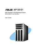
Download Intel SC5250-E computer case
Transcript
® Intel Entry Server Chassis SC5250-E Technical Product Specification Intel order number C32881-001 Revision 1.02 February , 2004 Enterprise Platforms and Services Marketing Revision History Intel® Entry Server Chassis SC5250-E Revision History Date Revision Number Modifications 10/07/02 0.1 Initial review copy 11/25/02 0.4 Initial feedback incorporated 12/10/02 0.5 Engineering and Technical Marketing changes incorporated to document 2/3/02 0.7 Reviewed for grammar, replaced / edited drawings 3/112/03 1.0 Added MTBF information and part numbers. 5/30/03 1.01 Added SATA Upgrade Kit Information and support for: Intel Server Board SE7500CW2, Intel Server Board SE7501CW2, Intel Server Board S845WD1-E and Intel Server Board S875WP1. 2/15/04 1.02 Added APTWKTCOOLKIT information for SE7505VB2 and SE7210TP1E information. Revision 1.02 ii Intel order number C32881-001 Intel® Entry Server Chassis SC5250-E Disclaimers Disclaimers Information in this document is provided in connection with Intel® products. No license, express or implied, by estoppel or otherwise, to any intellectual property rights is granted by this document. Except as provided in Intel's Terms and Conditions of Sale for such products, Intel assumes no liability whatsoever, and Intel disclaims any express or implied warranty, relating to sale and/or use of Intel products including liability or warranties relating to fitness for a particular purpose, merchantability, or infringement of any patent, copyright or other intellectual property right. Intel products are not intended for use in medical, life saving, or life sustaining applications. Intel may make changes to specifications and product descriptions at any time, without notice. Designers must not rely on the absence or characteristics of any features or instructions marked "reserved" or "undefined." Intel reserves these for future definition and shall have no responsibility whatsoever for conflicts or incompatibilities arising from future changes to them. The Intel® Entry Server Chassis SC5250-E may contain design defects or errors known as errata which may cause the product to deviate from published specifications. Current characterized errata are available on request. Intel, Pentium, Itanium, and Xeon are trademarks or registered trademarks of Intel Corporation. *Other brands and names may be claimed as the property of others. Copyright © Intel Corporation 2003. iii Revision 1.02 Intel order number C32881-001 Table of Contents Intel® Entry Server Chassis SC5250-E Table of Contents 2. 3. Chassis.................................................................................................................................. 2 2.1 System Color ................................................................................................................... 2 2.2 Front Bezel Features ....................................................................................................... 2 2.3 Security............................................................................................................................ 2 2.4 I/O Panel.......................................................................................................................... 3 2.5 Chassis Views ................................................................................................................. 4 Chassis Power Subsystem.................................................................................................. 7 3.1 4. 450-Watt EPS 2.0 Power Supply ..................................................................................... 8 3.1.1 450-W Power Supply Mechanical Outline.................................................................. 8 3.1.2 450-W Power Supply Fan Requirements................................................................... 8 3.1.3 AC Power Line ........................................................................................................... 9 System Cooling .................................................................................................................. 10 4.1 Fan Configuration .......................................................................................................... 10 4.2 Fan Control .................................................................................................................... 10 4.3 Cooling Solution............................................................................................................. 10 4.4 Intel® APTWKTCOOLKIT for SE7505VB2 Intel® Server Board Configuration ............. 12 4.5 Remove the Wind Tunnel Assembly.............................................................................. 13 4.6 Installing the Intel® APTWKTCOOLKIT for SE7505VB2 Intel® Server Board .............. 15 4.7 Configuring CPU Duct Fan Assembly the Intel® APTWKTCOOLKIT for SE7505VB2 Intel® Server Board ................................................................................................................. 17 4.8 5. Install the Front Fan Spacers for the Fixed Hard Drive Bay .......................................... 20 System Peripheral Bays..................................................................................................... 22 5.1 3.5" Peripheral Drive Bay............................................................................................... 22 5.2 5.25” Peripheral Drive Bays ........................................................................................... 23 5.3 Hard Drive Bay .............................................................................................................. 23 5.4 SCSI Multi-Mode Termination........................................................................................ 23 5.5 SCSI Interface ............................................................................................................... 24 5.6 FET Short Protection ..................................................................................................... 24 5.7 Device SCSI ID.............................................................................................................. 24 5.8 Hard Drive Activity LED ................................................................................................. 25 5.9 Hard Drive Fault LED..................................................................................................... 25 5.10 Hot-Swap Drive Bay Electronics................................................................................. 27 Revision 1.02 iv Intel order number C32881-001 Intel® Entry Server Chassis SC5250-E 6. 5.10.1 SCSI HSBP Board Layout ...................................................................................... 28 5.10.2 SCSI Hot-Swap Backplane Specifications ............................................................. 28 5.10.3 SAF-TE Board Layout ............................................................................................ 29 5.11 SAF-TE Specifications................................................................................................ 30 5.12 Serial ATA (SATA) Hardware Overview ..................................................................... 30 Functional Specifications.................................................................................................. 31 6.1 7. 7.1 3.5-inch Hot-swap Hard Drive Bays............................................................................... 32 7.2 SATA Interface .............................................................................................................. 32 7.3 Device SATA ID............................................................................................................. 32 7.4 Hard Drive Activity LED ................................................................................................. 33 7.5 Hard Drive Fault LED..................................................................................................... 33 7.6 Hot-Swap Drive Bay Electronics .................................................................................... 35 7.6.1 SATA Board Layout ................................................................................................. 35 7.6.2 SATA Hot-swap Backplane Specifications............................................................... 37 Front Panel .................................................................................................................... 37 System Interconnection..................................................................................................... 39 8.1 Signal Definitions ........................................................................................................... 39 8.2 Chassis Internal Cables................................................................................................. 39 8.2.1 Front Panel cable ..................................................................................................... 39 8.2.2 USB cable ................................................................................................................ 39 8.2.3 Fan Connectors........................................................................................................ 39 8.3 Server Board Internal Cables ........................................................................................ 39 8.4 Accessory Cables .......................................................................................................... 40 8.4.1 ICMB Interface Card Cable ...................................................................................... 40 8.4.2 External SCSI Cable ................................................................................................ 40 8.5 9. Hot Swappable Controller (HSC) Hardware Configurations .......................................... 31 System Peripheral Bays..................................................................................................... 32 7.7 8. Table of Contents I/O Panel Connectors .................................................................................................... 40 Compatible Intel® Server Boards ...................................................................................... 41 9.1 Intel® Server Board SE7501BR2 Feature Set............................................................... 41 9.2 Intel® Server Board SE7500CW2 Feature Set.............................................................. 43 9.3 Intel® Server Board SE7501CW2 Feature Set.............................................................. 44 9.4 Intel® Server Board SE7505VB2 Feature Set................................................................ 45 9.5 Intel® Server Board S845WD1-E Feature Set .............................................................. 46 9.6 Intel® Entry Server Board S875WP1-E Feature Set ..................................................... 47 Revision 1.02 v Intel order number C32881-001 Table of Contents 9.7 Intel® Entry Server Chassis SC5250-E Intel® Entry Server Board SE7210TP1-E Feature Set .................................................. 48 10. Product Regulatory Compliance....................................................................................... 50 10.1 Product Safety Compliance ........................................................................................ 50 10.2 Product EMC Compliance .......................................................................................... 50 10.3 Product Regulatory Compliance Markings ................................................................. 51 10.4 Electromagnetic Compatibility Notices ....................................................................... 51 10.4.1 USA ........................................................................................................................ 51 10.4.2 FCC Verification Statement .................................................................................... 52 10.4.3 ICES-003 (Canada) ................................................................................................ 52 10.4.4 Europe (CE Declaration of Conformity) .................................................................. 52 10.4.5 Japan EMC Compatibility ....................................................................................... 53 10.4.6 BSMI (Taiwan)........................................................................................................ 53 11. Environmental Limits......................................................................................................... 54 11.1 System Office Environment ........................................................................................ 54 11.2 System Environmental Testing................................................................................... 54 12. Reliability, Serviceability, and Availability ....................................................................... 55 12.1 MTBF.......................................................................................................................... 55 12.2 Serviceability .............................................................................................................. 55 13. Upgradeability .................................................................................................................... 56 13.1 SCSI Hot-swap Drive Bay Upgrade............................................................................ 56 13.2 External SCSI Adapter Cable ..................................................................................... 57 13.3 SATA Hot-swap Drive Bay Upgrade........................................................................... 58 Appendix A: Chassis Spares and Accessories .................................................................... 59 Upgrade and Accessory Parts ................................................................................................. 59 Replacement and Spare Parts for SC5250-E.......................................................................... 59 Glossary..................................................................................................................................... 61 Reference Documents .............................................................................................................. 63 Revision 1.02 vi Intel order number C32881-001 Intel® Entry Server Chassis SC5250-E List of Figures List of Figures Figure 1. ATX 2.03 I/O Aperture ................................................................................................... 3 Figure 2. Front Closed View of Server Chassis SC5250-E .......................................................... 4 Figure 3. Rear Closed View of Server Chassis SC5250-E ........................................................... 5 Figure 4. Front Internal View for Server Chassis SC5250-E ........................................................ 6 Figure 5. Rear Internal View for Server Chassis SC5250-E ......................................................... 6 Figure 6. 450-W EPS 2.0 Power Supply....................................................................................... 8 Figure 7. Cooling Fan Configuration ........................................................................................... 10 Figure 8. Processor Wind Tunnel Illustration with Intel® Xeon™ Processor with 400MHz System Bus Speed............................................................................................................................ 11 Figure 9. Processor Wind Tunnel Illustration with Intel® Xeon™ Processor with 533MHz System Bus Speed............................................................................................................................ 12 Figure 10. Remove wind Tunnel for your Intel® Server Board SE7505VB2............................... 13 Figure 11. Remove the Retention Mechanism if present on your Intel® Server Board SE7505VB2.......................................................................................................................... 14 Figure 12. Remove Retention Mechanism when present on your Intel Server Board SE7505VB214 Figure 13. Remove the old (contaminated) thermal grease (letter A in the following figure) from the top of the processor........................................................................................................ 14 Figure 14. Install Retention Brackets .......................................................................................... 15 Figure 15. Install CPU Heatsink units (one per processor)......................................................... 16 Figure 16. Install CPU metal clips (one set per processor)......................................................... 16 Figure 17. CPU Air Duct Folding................................................................................................. 17 Figure 18. Attach CPU Air Duct to Rear system Fan .................................................................. 18 Figure 19. Install Rear system Fan assembly to System Chassis ............................................. 19 Figure 20. Installing Front spacers for the Fixed Hard Drive Bay ............................................... 20 Figure 21. Reinstalling Fan with Front spacers to the Fixed Hard Drive Bay ............................. 20 Figure 22. Securing Fan with Front spacers to the Fixed Hard Drive Bay .................................. 21 Figure 23. Drive Bay Locations for Server Chassis SC5250-E................................................... 22 Figure 24. Hot-swap Drive Bay, Front Isometric View ................................................................ 26 Figure 25. Hot-swap Drive Bay, Rear Isometric View ................................................................. 26 Figure 26. Drive Carrier with Air Baffle Installed ......................................................................... 27 Figure 27. Server Chassis SC5250-E SCSI Backplane.............................................................. 28 Figure 28. Server Chassis SC5250-E SAF-TE Board ................................................................ 29 Figure 29. Hot-swap Drive Bay, Front Isometric View ................................................................ 34 Revision 1.02 vii Intel order number C32881-001 List of Figures Intel® Entry Server Chassis SC5250-E Figure 30. Hot-swap Drive Bay, Rear Isometric View ................................................................. 34 Figure 31. Drive Carrier with Air Baffle Installed ......................................................................... 35 Figure 32. Intel® Server Chassis SC5200 and SC5250-E SATA Backplane ............................. 36 Figure 33. Front Panel Controls and Indicators .......................................................................... 38 Figure 34. Replacing System Fan from IDE Drive Carrier to the SCSI Drive Carrier ................. 56 Figure 35. External SCSI Adapter Cable Detail .......................................................................... 57 Figure 36. Replacing System Fan from IDE Drive Carrier to the SATA Drive Carrier ................ 58 Revision 1.02 viii Intel order number C32881-001 Intel® Entry Server Chassis SC5250-E List of Tables List of Tables Table 1. Chassis Dimensions (approximate) ................................................................................ 2 Table 2. System Power Summary................................................................................................. 7 Table 3. SCSI ID Assignments ................................................................................................... 24 Table 4. Hard Drive Activity LED ................................................................................................ 25 Table 5. Hard Drive Fault LED.................................................................................................... 25 Table 6. SATA Bus ID Assignments .......................................................................................... 32 Table 7. Hard Drive Activity LED with Intel® RAID Controller SRCS14L Installed .................... 33 Table 8. Hard Drive Fault LED with Intel® RAID Controller SRCS14L Installed ....................... 33 Table 9. Connector References ................................................................................................. 36 Table 10. Front Panel LED Functions......................................................................................... 38 Table 11. System Office Environment Summary ........................................................................ 54 Table 12. MTBF Calculations...................................................................................................... 55 Table 13. Maximum Maintenance Procedure Times .................................................................. 55 Revision 1.02 ix Intel order number C32881-001 Intel® Entry Server Chassis SC5250-E 1. Introduction Introduction This specification details the feature set of the Intel® Server Chassis SC5250-E, an entry-level server chassis designed for Intel® server board products. The server chassis SC5250-E is low cost and allows utilization of multiple platforms and configurations. The server chassis SC5250-E (KPTBASE450) is designed to address the value server market. It includes a single 450W power factor correction (PFC) power supply, and supports four non hot-swap hard drives. One tachometer fan that is mounted in front of the fixed drive cage, and one that is mounted at the rear of the chassis provide Main chassis cooling. This chassis is currently compatible with: Intel® Server Board SE7501BR2, Intel® Server Board SE7500CW2, Intel® Server Board SE7501CW2, Intel® Server Boards SE7505VB2, Intel® Server Board S845WD1-E, Intel® Server Board S875WP1-E and Intel® Server Board SE7210TP1-E. Two 5.25-inch, half-height drive bays are available for peripherals, such as CD-ROM and tape drives, and a removable access cover provides entry to the interior of the chassis. The rear I/O panel conforms to Advanced Technology Extended (ATX) Specification, Revision 2.03. The chassis supports seven full-length expansion cards. The chassis is provided with a front panel board designed for Server Standards Infrastructure (SSI) Entry E-Bay (EEB) 3.0-compliant server boards. An optional hot-swap drive bay kit, product code AXX2HSDRVUG, provides an upgrade path to allow the server chassis SC5250-E to support five hot-swap drives. This optional hot-swap SCSI hard disk drive bay supports up to five 1-inch single connector attachment (SCA) low-voltage differential SCSI (LVD) hard drives to enhance serviceability, availability, and upgradeability of the system. When the hot-swap drive bay is installed, it replaces the fixed hard drive bay. An optional hot-swap upgrade drive bay assembly (ASATAHSDB) is available for the Server Chassis SC5200 and Server Chassis SC5250-E. It should be mounted in place of the middle three 5.25-inch drive trays of the base, non-redundant chassis models. For the redundant power models, the upgrade accessory should be installed in the lower three 5.25-inch drive trays to bring the total number of available hot-swap SATA drives to eight. Refer to the Intel® Server Chassis SC5200/SC5250-E Hot-swap Bay Upgrade Kit for complete installation instructions. Note: Part of the replacement process requires removing the fan from the fixed hard drive bay attaching it to the rear of the hot-swap drive bay. An optional passive processor cool kit (APTWKTCOOLKIT) is available for the Intel Server Chassis SC5250-E and SE7505VB2 only. It should be mounted in place of the boxed board processor active heatsinks and fan solutions. The APTWKTCOOLKIT requires BIOS 1.08 or newer releases for SE7505VB2. Refer to the Intel® Server Chassis SC5200/SC5250-E Hotswap SCSI Bay Upgrade Kit for complete installation instructions. This specification details the key features of the product. Reference documents listed at the back of this document provide additional product specification details for the server boards, backplanes, and power supplies validated for use with this chassis. Check the compatibility section on the support website for more details: http://support.intel.com/support/motherboards/server/chassis/SC5250-E/. Revision 1.02 1 Intel order number C32881-001 Chassis 2. Intel® Entry Server Chassis SC5250-E Chassis Table 1. Chassis Dimensions (approximate) Configuration 2.1 Pedestal Height 17.8 inches (452mm) 17.6 inches (447mm) if feet are removed Width 9.256 inches (235mm) Depth 26 inches (66.04mm) Clearance Front 17.83 inches (452mm). 19.1 inches with bezel (485mm) Clearance Rear 5 inches (12.7mm) Clearance Side 3 inches (7.62mm) additional side clearance is needed for service access System Color The Intel® Server Chassis SC5250-E is offered in two color options: • • 2.2 Dusty beige (GE BR7026) Order code KPTBASE450 Black (GE701) Order code KPTBASE450BLK Front Bezel Features The standard front bezel is molded plastic and attaches to the front of the chassis with a hinge on the right side and two snaps on the left. The snaps at the left attach behind the access cover, preventing accidental removal of the bezel. The bezel can only be removed by first removing the server access cover. This provides additional security to the hard drive and peripheral bay area. The bezel includes a key-locking door that covers the drive cage area. The peripheral bays are covered with plastic snap-in cosmetic pieces that must be removed to add peripherals to the system. Front panel buttons and lights are located along right side the peripheral bays. 2.3 Security A variety of chassis security options are provided at the system level, as listed below. • A removable padlock loop at the rear of the system access cover can be used to prevent access to the microprocessors, memory, and add-in cards. A variety of lock sizes can be accommodated by the 0.270-inch diameter loop. • A two-position key lock/switch will unlock the front bezel. • A chassis intrusion switch is provided allowing server management software to detect unauthorized access to the system cover. Revision 1.02 2 Intel order number C32881-001 Intel® Entry Server Chassis SC5250-E Chassis Note: See the technical product specification appropriate to the server board for a description of BIOS and management security features for each specific supported platform. The technical product specifications can be found at http://support.intel.com 2.4 I/O Panel All input/output (I/O) connectors are accessible on the rear of the chassis. The SSI E-bay 3.0 compliant chassis provides an ATX* 2.03-compatible cutout for I/O shield installation. Boxed Intel server boards provide the required I/O shield for installation in the cutout. The I/O cutout dimensions are shown in Figure 1 below for reference. R 0.039 MAX, TYP 0.100 Min keepout around opening 1.750 ± 0.008 (0.150) I/O Aperture 6.250 ± 0.008 Baseboard 5.196 ± 0.010 Datum 0,0 (0.650) Figure 1. ATX 2.03 I/O Aperture Revision 1.02 3 Intel order number C32881-001 Chassis 2.5 Intel® Entry Server Chassis SC5250-E Chassis Views A B C D E F TP00053B A. B. C. D. E. F. Front panel controls and indicators (See Section 7.7, Figure 22 for details) Two 5.25-inch removable media drive bays 3.5-inch removable media drive bay Internal hard drive bay cage (behind door) Security lock USB port Figure 2. Front Closed View of Server Chassis SC5250-E Revision 1.02 4 Intel order number C32881-001 Intel® Entry Server Chassis SC5250-E Chassis A B C D E F G H TP00054B I J A. B. C. D. E. F. G. H. I. J. K. K Alternate Serial B port knockout Alternate ICMB or external SCSI knockout AC input power connector Power supply Fan I/O ports* Expansion slot covers ICMB or external SCSI knockout Serial B port knockout Location to install padlock loop Chassis intrusion switch Figure 3. Rear Closed View of Server Chassis SC5250-E Revision 1.02 5 Intel order number C32881-001 Chassis Intel® Entry Server Chassis SC5250-E TP00053C Figure 4. Front Internal View for Server Chassis SC5250-E TP00054C Figure 5. Rear Internal View for Server Chassis SC5250-E Revision 1.02 6 Intel order number C32881-001 Intel® Entry Server Chassis SC5250-E 3. Chassis Power Subsystem Chassis Power Subsystem The Intel® Server Chassis SC5250-E supports a typical PS/2* form factor power supply with a remote enable feature. The remote enable feature permits the system power to be activated from a variety of sources, allowing the implementation of Wake on LAN (WOL) or other remote management features. The 450-Watt entry power supply (EPS) features and entry SSI (Rev. 3.0) compliant server board connectors. It is positioned as the entry power supply solution for the Intel® server boards SE7505VB2, SE7501BR2, SE7500CW2, SE7501CW2, S845WD1-E, and S875WP1-E. Refer to the 450-W EPS 1.0 Power Supply Specification for details. Table 2. System Power Summary Component Intel Part Number A85459-005 SC5250-E 450-Watt EPS +3.3 VDC Output 24 Amp Max +5 VDC Output 20 Amp Max +12 VDC Output 30 Amp Sustained 36 Amp / 12 second peak current -12 VDC Output 0.5 Amp Max +5 VDC Standby 2.0 Amp Max Multiple +12V 240 VA Protection Circuits Yes (2) Output Balancing Total combined output power of +3.3v and +5v shall not exceed 179 W. DC Power Connections 24-pin, 8-pin AC Line Voltage Auto-ranging for either 100-127 VAC or 200-240 VAC AC Line Frequency 50/60 Hz AC Input Current (System AC Rating) 5.0 Amp at 115 VAC 2.5 Amp at 220 VAC Redundant Power No Hot-swap Power Modules No Dual Line Cords No Redundant Fans No Replaceable Fans No Intended server board Intel® Server Board SE7505VB2 Intel® Server Board SE7501BR2 Intel® Server Board SE7500CW2 Intel® Server Board SE7501CW2 Intel® Server Board S845WD1-E Intel® Server Board S875WP1-E Intel® Server Board SE7210TP1-E Revision 1.02 7 Intel order number C32881-001 Chassis Power Subsystem 3.1 3.1.1 Intel® Entry Server Chassis SC5250-E 450-Watt EPS 2.0 Power Supply 450-W Power Supply Mechanical Outline The mechanical outline and dimensions for the 450-W supply are an extended PS/2 form factor. The approximate dimensions are 86-mm (3.3 inches) high by 150-mm (5.90 inches) wide by 180-mm 7.09 (inches) deep. Figure 6. 450-W EPS 2.0 Power Supply 3.1.2 450-W Power Supply Fan Requirements The 450-W EPS power supply incorporates an 80-mm low acoustic noise fan to exhaust air. The sound pressure level is measured at a distance of 1.0 meter from each side of the power supply in a free field. The worst-case peak value of the measurements shall not exceed 43 dBA at 25°C inlet temperature. Revision 1.02 8 Intel order number C32881-001 Intel® Entry Server Chassis SC5250-E 3.1.3 Chassis Power Subsystem AC Power Line The system is specified to operate from 100-127VAC, 200-240VAC, at 50 or 60 Hz. The specified PFC power supplies are auto-ranging. The system is tested to meet these line voltages, and has been tested, but not specified, at ±10% of the voltage ranges, and at ±3 Hz on the line input frequency. The system is specified to operate without error at full power supply output load, nominal input voltage, with line source interruptions not to exceed one period of the AC input power frequency (i.e., 20 milliseconds at 50 Hz). The system is not damaged by AC surge ring wave up to 2.0kV/500A. This ring wave is a 100 kHz-damped oscillatory wave with a specified rise time for the linear portion of the initial halfcycle of 0.5µsec. Additionally, the system will not be damaged by a unidirectional surge waveform of up to 2.0kV /3000A, with a 1.2µsec rise time and 50µsec duration. Additional details on these waveforms can be obtained in ANSI/IEEE STD C62.45-1992. Revision 1.02 9 Intel order number C32881-001 System Cooling Intel® Entry Server Chassis SC5250-E 4. System Cooling 4.1 Fan Configuration The cooling sub-system in the Intel Server Chassis SC5250-E consists of two system fans and one power supply fan. A 92mm x 25mm fan located in the front of the fixed hard drive cage draws fresh air into the chassis from the front and provides cooling for the hard drive bay. A 120mm x 38mm fan provides cooling at the rear of the chassis, exhausting warm air out of the system. The power supply fan assists in drawing air through the peripheral bay area, through the power supply and exhausting it out the rear of the chassis. In addition to these pre-installed fans, locations for three additional fans are provided for customized configurations. Intel does not provide order part numbers for these customizable fan options. A 120mm fan can be mounted to the rear of the PCI card guide and provide additional cooling to the PCI card area and two 80mm fans can be mounted at the front of the chassis to the right of the hard drive bay opening to provide more cooling. 4.2 Fan Control The fans provided in the server chassis SC5250-E contain a tachometer signal that can be adjusted by the Server Management subsystem for the Intel Server Board SE7501BR2. See the specific baseboard Technical Product Specification for details on how this feature works. 4.3 Cooling Solution Air should flow through the system from front to back as indicated by the arrows in the figure below. Figure 7. Cooling Fan Configuration The Intel® Server Chassis SC5250-E is engineered to provide sufficient cooling for all internal components of the server including the power subsystem, server board, processors, memory, add-in PCI cards, and installed hard drives and removable media drives. Revision 1.02 10 Intel order number C32881-001 Intel® Entry Server Chassis SC5250-E System Cooling The server chassis SC5250-E cooling subsystem is dependent upon proper airflow. The designated cooling vents on both the front and back of the chassis must be left open and must not be blocked by improperly installed devices. All internal cables must be routed in a manner that does not impede airflow. The active processor cooling solution validated with this chassis is called a Processor Wind Tunnel (PWT), and is provided with the boxed Intel® Xeon processors. To ensure proper cooling, only processors with active heatsinks should be used unless otherwise indicated in the server board manuals. Active heatsinks incorporate a fan to provide cooling. This thermal solution is included with boxed Intel® Xeon™ processors. Proper installation of the processor wind tunnel and fan places the fan portion of the PWT towards the front edge of the chassis, blowing air toward the rear of the chassis (toward I/O connectors). Figure 8. Processor Wind Tunnel Illustration with Intel® Xeon™ Processor with 400MHz System Bus Speed Revision 1.02 11 Intel order number C32881-001 System Cooling Intel® Entry Server Chassis SC5250-E Figure 9. Processor Wind Tunnel Illustration with Intel® Xeon™ Processor with 533MHz System Bus Speed 4.4 Intel® APTWKTCOOLKIT for SE7505VB2 Intel® Server Board Configuration The Workstation Cooling Kit was designed to work with the Intel Server Board SE7505VB2 and Intel Server Chassis SC5250-E, to dramatically reduce system level acoustics making it an effective solution when acoustics is a concern. Intel product code APTWKTCOOLKIT (Intel MM # 858795). Bios version 1.08 or newer is required for proper performance. In addition, it is recommended that system fans be connected to the Intel® server board SYS Fan header #1 and SYS Fan header #3 for the chassis fans. BIO 1.08 includes support for new APWKTCOOLKIT for SC5250-E configurations and SE7505VB2. BIOS 1.08 with SE7505VB2 Fab -701 or later on SC5250-E only, requires BIOS system set up configurations via BIOS “Setup Configuration Utility”. Settings must be configured as follows: Select “Advanced” menu option, Select "Hardware monitor" option, Select "Chassis Type," and select "SC5250-E” for Pilot Point 1 configurations. Revision 1.02 12 Intel order number C32881-001 Intel® Entry Server Chassis SC5250-E System Cooling New BIOS release 1.08 provides new fan control changes to improve acoustics. In addition, Intel offers a new upgrade kit for maximum improvement on workstations environments, with C15472-701 level boards. BIOS releases contain critical errata fixes. Therefore, Intel recommends updating the BIOS on this board to the most current release. BIOS releases available for the server board SE7505VB2 are available at http://support.intel.com/support/motherboards/server/se7505vb2. See the release notes available with the BIOS release for installation instructions and corrections available in the release. 4.5 Remove the Wind Tunnel Assembly The Intel® Workstation Acoustic Kit can be used to retrofit either a new or existing Intel® Server Board SE7505VB2 system in the Intel® Server Chassis SC5250-E. It replaces the active heatsink solution presented on Section 4.2. Please refer to Intel® WorkStation Cooling Kit User’s Guide for complete instructions for removal of Active heatsink Solution (Order Number: C55113-001, Rev. 2) C A B B TP00495 Figure 10. Remove wind Tunnel for your Intel® Server Board SE7505VB2 Revision 1.02 13 Intel order number C32881-001 System Cooling Intel® Entry Server Chassis SC5250-E E D B C A TP00502 Figure 11. Remove the Retention Mechanism if present on your Intel® Server Board SE7505VB2 . A TP00496 Figure 12. Remove Retention Mechanism when present on your Intel Server Board SE7505VB2 A TP00497 Figure 13. Remove the old (contaminated) thermal grease (letter A in the following figure) from the top of the processor Revision 1.02 14 Intel order number C32881-001 Intel® Entry Server Chassis SC5250-E 4.6 System Cooling Installing the Intel® APTWKTCOOLKIT for SE7505VB2 Intel® Server Board The Workstation Cooling Kit was designed to work with the Intel Server Board SE7505VB2 and Intel Server Chassis SC5250-E to dramatically reduce system level acoustics making it an effective solution when acoustics is a concern. Intel Part Number: APTWKTCOOLKIT (Intel MM # 858795). Please refer to Intel® WorkStation Cooling Kit User’s Guide for complete installation instructions (Order Number: C55113-001, Rev. 2) Do not install the Intel® Workstation Acoustic Kit in systems with only one processor. This kit is designed for two-processor systems. If you only have one processor installed, the large opening left by the second processor and heat sink will reduce the airflow through the single processor’s heat sink and may cause the system to overheat. The following items are included in the kit: • Two heat sinks • A flexible air duct • Four plastic retention mechanisms (two per heat sink) • Eight coarse- thread screws (two per retention mechanism) • Four metal retention clips (two per heat sink) for 400 Mhz FSB processors • Four metal retention clips (two per heat sink) for 533 Mhz FSB processors • Four nylon rivets for air duct attachment to rear system fan • Four plastic spacers • Eight fine-thread screws (two per spacer) Install the Retention Brackets (two per heat sink) that came with your Intel® Workstation Acoustic Kit. Use the screws that came with the kit. Note that all the Retention Brackets are identical. A TP00498 Figure 14. Install Retention Brackets Revision 1.02 15 Intel order number C32881-001 System Cooling Intel® Entry Server Chassis SC5250-E A A TP00499 TP00499 Figure 15. Install CPU Heatsink units (one per processor) Position the metal clips that came with your Intel® Workstation Acoustic Kit as shown in the following figure 16. Make sure that the center tab (letter B in the following figure) engages the slot in the heat sink base (number 1in the figure). Repeat Steps 4-6 for second retention clip. A C B D 1 3 2 4 TP00575 Figure 16. Install CPU metal clips (one set per processor) Revision 1.02 16 Intel order number C32881-001 Intel® Entry Server Chassis SC5250-E 4.7 System Cooling Configuring CPU Duct Fan Assembly the Intel® APTWKTCOOLKIT for SE7505VB2 Intel® Server Board Fold the Air Duct that came with your Intel® Workstation Acoustic Kit as illustrated in figure 17. Make sure that the black marker lines are positioned towards the inside of the Air Duct. Begin with fold #1 and proceed through fold #7. Completed Air Duct should look like left and right views (see #8 and #9 in the following figure). 3 4 7 1 2 View from left corner 5 6 8 View from 9 right corner TP00493 Figure 17. CPU Air Duct Folding Attach Air Duct to Rear System Fan. Locate the air direction arrow on the side of the Rear System Fan and position fan as shown in the following figure. (The label on the Rear System Fan should face towards the back of the system chassis and the finger guard should face towards the server board.) Ensure that the Fan Power Cable (letter B in the figure) exits at lower right-hand corner. Revision 1.02 17 Intel order number C32881-001 System Cooling Intel® Entry Server Chassis SC5250-E E C A D B TP00494 Figure 18. Attach CPU Air Duct to Rear system Fan 1. Place Finger Guard (letter C in the figure) against matching holes in Rear System Fan. 2. Place folded Air Duct (letter D in figure) against matching holes in Finger Guard and Rear System Fan. 3. Fasten Rear System Fan, Finger Guard and Air Duct together by inserting a nylon rivet at each of the four mounting holes. Use the new nylon rivets that came with your Intel® Workstation Acoustic Kit. Do not re-use the old nylon rivets. Note that the nylon rivets insert from the inside of the fan (see letter E in figure). Revision 1.02 18 Intel order number C32881-001 Intel® Entry Server Chassis SC5250-E System Cooling A C B C TP00501 Figure 19. Install Rear system Fan assembly to System Chassis Revision 1.02 19 Intel order number C32881-001 System Cooling 4.8 Intel® Entry Server Chassis SC5250-E Install the Front Fan Spacers for the Fixed Hard Drive Bay Install the Front Fan Spacers for systems with a standard fixed hard drive bay cage. The following instructions do not apply to systems with a hot-swappable hard drive bay cage. Use four screws to attach the four plastic spacers to the unlabeled side of the Front Fan. Insert screw (letter B in the following figure) from the inside of the Front Fan to secure the plastic spacer (letter A in the figure). Hold the screw steady with your thumb while using a hex driver (letter C in figure) to secure the plastic spacer to the screw. A C B TP00573 Figure 20. Installing Front spacers for the Fixed Hard Drive Bay 1. Insert the Front Fan into the hard drive bay cage. Make sure that the Front Fan cable is positioned at the bottom of the cage. Make sure that the airflow is towards the server board. This means that the label should face to the inside of the hard drive bay cage (towards the server board). The plastic spacers should be facing towards the front grill of the hard drive bay cage. TP00571 Figure 21. Reinstalling Fan with Front spacers to the Fixed Hard Drive Bay Revision 1.02 20 Intel order number C32881-001 Intel® Entry Server Chassis SC5250-E System Cooling 2. Use four screws to secure the Front Fan to the hard drive bay cage. TP00572 Figure 22. Securing Fan with Front spacers to the Fixed Hard Drive Bay Revision 1.02 21 Intel order number C32881-001 System Peripheral Bays Intel® Entry Server Chassis SC5250-E 5. System Peripheral Bays 5.1 3.5" Peripheral Drive Bay The Intel® Server Chassis SC5250-E provides for the installation of a 3.5-inch peripheral, such as a floppy drive, below the 5.25-inch peripheral bays. The bezel must be removed prior to floppy drive installation. When a floppy drive is not installed, a snap-in EMI shield must be in place to ensure regulatory compliance. Cosmetic plastic filler is provided to snap into the bezel. The 3.5” bay is designed so that screws are only required on the left side of the chassis, as indicated in the figure below. On the right side of the chassis, two protrusions in the sheet metal hold the drive in place. Figure 23. Drive Bay Locations for Server Chassis SC5250-E Revision 1.02 22 Intel order number C32881-001 Intel® Entry Server Chassis SC5250-E 5.2 System Peripheral Bays 5.25” Peripheral Drive Bays The SC5250-E chassis supports two half-height or one full-height 5.25-inch removable media peripheral device, such as a magnetic/optical disk, CD-ROM, or tape drive. These peripherals can be up to 9 inches (228.6mm) deep. As a guideline, the maximum recommended power per device is 18W. Thermal performance of specific devices must be verified to ensure compliance to the manufacturer’s specifications. The 5.25-inch peripherals are removable from the front of the chassis after taking off the access cover and removing the front bezel. EMI shield panels are installed and should be retained in unused 5.25-inch bays to ensure proper cooling and EMI conformance. Note: Caution when approaching the maximum level of integration for the 5.25-inch drive bays. Power consumption of the devices integrated needs to be carefully considered to ensure that the power supply maximum power levels are not exceeded. Typical configurations can supply enough power for a floppy drive, a tape drive, a CD-ROM, and four fixed hard drives. 5.3 Hard Drive Bay The server chassis SC5250-E comes with a removable hard drive bay that can accept up to six cabled 3.5” x 1” hard drives. Power requirements for each individual hard drive may limit the maximum number of drives that can be integrated to a server chassis SC5250-E. This bay has a 92mm (6.2 inches) x 25mm fan mounted to the front to provide airflow to the hard drives mounted in it. The drive bay secures with two screws in the front of it and two screws on the side. Note: The hard drive bay must be slid forward or removed to install the baseboard. The server chassis SC5250-E server chassis is capable of accepting a single SCSI hot swap backplane hard drive enclosure in place of the fixed drive bay. This is the same enclosure that is used in the Intel Server Chassis SC5100 and SC5200. The backplane is an LVD/SE SCSI design, which provides support for SCSI devices, using Low Voltage Differential Signaling, as well as support for older SE SCSI devices (Ultra 160 and older). The backplane has a connector to accommodate a SAF-TE controller on an add-in card. The backplane supports five 1-inch hot-swap SCA-2 drives when mounted in the docking drive carrier. 5.4 SCSI Multi-Mode Termination The multi-mode terminators provide SCSI-4 compliant termination for the backplane. These terminators provide termination in both SE modes and LVD mode. Installing a single SE drive forces all installed drives to run in the SE termination mode on the SCSI bus. Revision 1.02 23 Intel order number C32881-001 System Peripheral Bays 5.5 Intel® Entry Server Chassis SC5250-E SCSI Interface 1 The SCSI interface on the server chassis SC5250-E LVD/SE SCSI backplane provides the link between the SCSI bus and the microcontroller (containing the intelligence for the server chassis SC5250-E 1 LVD/SE SCSI backplane). This interface allows the microcontroller to respond as a SCSI target to implement the SAF-TE protocol. Power control on the server chassis SC5250-E 1 LVD/SE SCSI backplane supports: • Spin-down of a drive when failure is detected and reported (using enclosure services messages) via the SCSI bus. An application or RAID controller detects a drive-related problem that indicates a data risk. In response, it removes the drive from service and sends a spin-down SCSI command to the drive. This decreases the likelihood that the drive will be damaged during removal from the hot-swap drive bay. When a new drive is inserted, the power control waits a small amount of time for the drive to be fully seated, and then applies power with a controlled power ramp. • If the system power is on, the LVD/SE SCSI backplane immediately powers off a drive slot when it detects that a drive has been removed. This prevents possible damage to the drive when it is partially removed and re-inserted while full power is available and disruption of the entire SCSI array from possible sags in supply voltage and resultant current spikes. 5.6 FET Short Protection The Field Effect Transistor (FET) short protection circuit is useful to protect both 12-volt and 5volt power control FETs located on LVD/SE SCSI backplane. 5.7 Device SCSI ID Each device on a SCSI bus must have a unique SCSI ID. The 5 x 1.0” LVD/SE SCSI backplane device SCSI ID is dependent on whether it is configured as a primary or a secondary backplane. This configuration is defined by the logic of pin 1 on the I2C connector (J2A1). Note: The server chassis SC5250-E will only support a single backplane; therefore it will always be identified as primary on the I2C bus. Table 3. SCSI ID Assignments Device Drive 1 Drive 2 Drive 3 Drive 4 Drive 5 SAF-TE Controller SCSI ID as Primary Backplane I2C* connector (J2A1) pin1=1 0x0H 0x1H 0x2H 0x3H 0x4H 0x6H SCSI ID as Secondary Backplane I2C connector (J2A1) pin1=0 0x8H 0x9H 0xAH 0xBH 0xCH 0x5H 1 The SCSI backplane board set used for the server chassis SC5250-E chassis is the same as that which is used used in the server chassis SC5100/SC5200 chassis. Revision 1.02 24 Intel order number C32881-001 Intel® Entry Server Chassis SC5250-E 5.8 System Peripheral Bays Hard Drive Activity LED Each SCSI drive turns on a green LED when it is accessed. The LEDs are 4-terminal dual-color (yellow and green) physically located on the backplane. Table 4. Hard Drive Activity LED 5.9 Drive 1 HSBP LED Activated 1 LED Designator DS5A1 LED Color Green 2 2 DS5B1 Green 3 3 DS5C1 Green 4 4 DS5D1 Green 5 5 DS5E1 Green Hard Drive Fault LED The hot-swap controller (HSC) is responsible for turning the drive fault LEDs on or off according to the states specified via commands received from SAF-TE and the IMB. The drive fault LEDs are yellow and indicate failure status for each drive. The LEDs are physically located on the LVD/SE SCSI backplane. The LEDs are 4-terminal dual-color (yellow and green) physically located on the backplane. Table 5. Hard Drive Fault LED Drive 1 HSBP LED Activated 1 LED Designator DS5A1 LED Color Yellow 2 2 DS5B1 Yellow 3 3 DS5C1 Yellow 4 4 DS5D1 Yellow 5 5 DS5E1 Yellow Revision 1.02 25 Intel order number C32881-001 System Peripheral Bays Intel® Entry Server Chassis SC5250-E Figure 24. Hot-swap Drive Bay, Front Isometric View Figure 25. Hot-swap Drive Bay, Rear Isometric View Revision 1.02 26 Intel order number C32881-001 Intel® Entry Server Chassis SC5250-E System Peripheral Bays Figure 26. Drive Carrier with Air Baffle Installed 5.10 Hot-Swap Drive Bay Electronics The hot-swap SCSI backplane board set supports the following features: • • Hot-swapping of SCSI drives that allows connecting SCSI devices while the system power is on. Enclosure management and monitoring functions conforming to the SCSI-Accessed Fault-Tolerant Enclosures Specification (SAF-TE), Revision 1.00. Revision 1.02 27 Intel order number C32881-001 System Peripheral Bays 5.10.1 Intel® Entry Server Chassis SC5250-E SCSI HSBP Board Layout The following diagram shows the layout of components and connectors on the hot-swap SCSI backplane printed circuit board set. This solution consists of two separate boards. The first board provides power distribution and SCSI interfacing of the drives. The second board provides the SAF-TE features and drive failure indicators. Figure 27. Server Chassis SC5250-E SCSI Backplane 5.10.2 SCSI Hot-Swap Backplane Specifications The server chassis SC5250-E hot-swap SCSI backplane is an embedded application subsystem that does the following during normal operation: • • • Responds to SAF-TE messages transmitted to the backplane via the SCSI bus. Monitors the temperature on the backplane, and reports a warning or critical error if outside programmed limits (if the server baseboard has a BMC-based management system). Monitors the speed of the fans, if present, and reports a warning or critical error if outside programmed limits (if the server baseboard has a BMC-based management system). Revision 1.02 28 Intel order number C32881-001 Intel® Entry Server Chassis SC5250-E System Peripheral Bays The server chassis SC5250-E hot-swap SCSI backplane board set is made up of the following functional blocks: • • • • • • • • SCSI Bus with SCA drive connectors, and active LVDS terminators Microcontroller with program flash and RAM SCSI interface that allows the microcontroller to respond as a SCSI target I2C interface to server board SCSI drive power control Fault indicator support (availability dependent on server baseboard management subsystem) Support for two cooling fans (fan-tachometer inputs and power control) Temperature sensor (availability dependent on server baseboard management subsystem) The hot-swap SCSI backplane board set resides in the hot-swap drive bay enclosure that is available as an upgrade to the server chassis SC5250-E. 5.10.3 SAF-TE Board Layout Figure 28. Server Chassis SC5250-E SAF-TE Board Revision 1.02 29 Intel order number C32881-001 System Peripheral Bays Intel® Entry Server Chassis SC5250-E 5.11 SAF-TE Specifications The server chassis SC5250-E hot-swap SCSI backplane board set performs the tasks associated with hot-swappable SCSI drives, enclosure (chassis) monitoring and management, as specified in the SCSI-Accessed Fault-Tolerant Enclosures Specification (SAF-TE), Revision 1.0. The SAF-TE specified features supported by the hot-swap SCSI backplane include, but are not limited to monitoring the SCSI bus for enclosure services messages, and acting on them appropriately. Examples of such messages include: activate a drive fault indicator, power down a drive that has failed, and report backplane temperature. The SAF-TE intelligent agent acts as a proxy for “dumb” I2C devices during intra-chassis communications. These devices have no bus mastering capability. 5.12 Serial ATA (SATA) Hardware Overview Up to two SATA backplanes (supporting up to eight drives) can be mounted in a Server Chassis SC5200 if a SATA controller is installed. One SATA backplane can be mounted in the Server Chassis SC5250-E. Each SATA backplane supports the connection of up to four SATA drives. When two SATA backplanes are mounted, one is designated the ‘Primary SATA Backplane’ and the second is designated the ‘Secondary SATA Backplane’. These terms are used to be consistent with other backplanes in other server system products. Revision 1.02 30 Intel order number C32881-001 Intel® Entry Server Chassis SC5250-E 6. Functional Specifications Functional Specifications The hot-swap backplane is responsible for the following system functions: • Drive Fault Light Control - SATA Specification, revision 1.0 does not support fault detection. However, when the Intel® RAID Controller SRCS14L (with 2x5 LED cable) is installed, fault detection is supported. Turning off the green LED does this when a fault occurs. Note that this is different from previous generations where an amber LED would signify a fault condition. If a different type of SATA controller is used, fault light control is not supported. The RAID Controller SRCS14L provides a 2x5 LED header, which is connected between the backplane and drive fault lights. Currently, no other SATA controllers on the market provide this 2x5 LED header. • Drive Presence Detection - Detects drive presence and makes this information available by turning on the green LED. Note that this is also different from previous generation backplanes. This functionality works regardless of which SATA controller is being used. • Drive Power Control - Unlike previous generation backplanes, power is always applied to slots; hot swap functionality is provided via a mating drive connector. This is accomplished by using different length pins on both the drive side and the backplane. A resistor on the pre-charge pins for both the 12V and 5V rails limits the in-rush current. 6.1 Hot Swappable Controller (HSC) Hardware Configurations There are two possible configurations (“Primary” and “Secondary”) available for the SATA backplane on the Server Chassis SC5200. There is no differentiation between backplanes, however, and from a user’s perspective, all drives are treated in the same manner as if they were connected directly to the controller, thereby making the backplane appear transparent. Revision 1.02 31 Intel order number C32881-001 System Peripheral Bays Intel® Entry Server Chassis SC5250-E 7. System Peripheral Bays 7.1 3.5-inch Hot-swap Hard Drive Bays The SATA backplane provides support for SATA devices using Low Voltage Differential Signaling. The backplane has a connector to accommodate a SAF-TE controller on an add-in card. The backplane supports four 1-inch hot-swap SATA drives when mounted in the docking drive carrier. When a RAID Controller SRCS14L is installed, two SATA backplanes may be connected for a total of eight SATA drives (valid only in 650-W redundant chassis). The Server Chassis SC5250-E supports only one SATA hot-swap drive bay, supporting four 3.5-inch wide SATA hard drives. Drives are accessible by opening the front access door. Four metal carriers are provided with each hot-swap bay to mount the hard drives. Each carrier features a plastic handle and bezel with an activity/fault indicator. When no drive is installed in a carrier, the air baffle should remain in place to ensure proper cooling of the hard drives. The Intel® Server Chassis SC5250-E, hot-swap drive bay is designed to accept four one-inch peripherals that consume a maximum of 18 W of power each. This wattage number is intended as a guideline. Thermal performance of specific hard drives must be verified to ensure compliance to the drive manufacturer’s specifications. A compatibility list of supported Intel® server boards for the Server Chassis SC5200 and Server Chassis SC5250-E is available on support.intel.com (URL: http://support.intel.com/). An optional hot-swap upgrade drive bay assembly (ASATAHSDB) is available for the Server Chassis SC5200 and Server Chassis SC5250-E. It should be mounted in place of the middle three 5.25-inch drive trays of the base, non-redundant chassis models. For the redundant power models, the upgrade accessory should be installed in the lower three 5.25-inch drive trays to bring the total number of available hot-swap SATA drives to eight. Refer to the Intel® Server Chassis SC5200 and SC5250-E Hot-swap Bay Upgrade Kit for installation instructions. 7.2 SATA Interface The SATA interface for the SATA backplane provides the link between the SATA bus and the microcontroller. 7.3 Device SATA ID Each device on a SATA bus must have a unique ID. The 4 x 1.0” backplane device ID is dependent on the connection to the controller. The recommended configuration for the RAID Controller SRCS14L is listed in the following table. It is important that the user follow this recommendation to ensure that the drive activity and fault LEDs correspond to the correct drive. It is not critical to follow a specific connection scheme if a different SATA controller is used as other controllers do not provide activity and fault LEDs via a 2x5 LED header. Table 6. SATA Bus ID Assignments Revision 1.02 32 Intel order number C32881-001 Intel® Entry Server Chassis SC5250-E 7.4 System Peripheral Bays SATA Drive # Drive 0 Intel® RAID Controller SRCS14L Channel A0 Drive 1 A1 Drive 2 A2 Drive 3 A3 Hard Drive Activity LED When a drive is first plugged in, the green LED turns on and stays on signifying that the drive has been detected. The green LED will then blink if there is activity to the drive and a RAID Controller SRCS14L with 2x5 LED header has been installed. The LEDs are 4-terminal dualcolor (yellow and green) LEDS that are physically located on the backplane. Table 7. Hard Drive Activity LED with Intel® RAID Controller SRCS14L Installed 7.5 Drive 0 Hot-swap Backplane LED Activated 0 LED Designator DS4E1 LED Color Blinking Green 1 1 DS4D1 Blinking Green 2 2 DS4C1 Blinking Green 3 3 DS4B1 Blinking Green Hard Drive Fault LED Hard drive fault indication is not currently supported as per the SATA 1.0 Specification. However, if a fault occurs on a drive and the backplane is connected to a RAID Controller SRCS14L with the 2x5 LED header installed, the green LED will turn off when a fault occurs. Table 8. Hard Drive Fault LED with Intel® RAID Controller SRCS14L Installed Drive Hot-swap Backplane LED Activated 0 0 LED Designator DS4E1 LED Color Green Off 1 1 DS4D1 Green Off 2 2 DS4C1 Green Off 3 3 DS4B1 Green Off Revision 1.02 33 Intel order number C32881-001 System Peripheral Bays Intel® Entry Server Chassis SC5250-E Figure 29. Hot-swap Drive Bay, Front Isometric View Figure 30. Hot-swap Drive Bay, Rear Isometric View Revision 1.02 34 Intel order number C32881-001 Intel® Entry Server Chassis SC5250-E System Peripheral Bays Figure 31. Drive Carrier with Air Baffle Installed 7.6 Hot-Swap Drive Bay Electronics The hot-swap SATA backplane board set supports the following features: • • Hot-swapping of SATA drives, which allows connection of SATA devices while the system is powered on. Management and monitoring functions conforming to the SATA 1.0 Specification 7.6.1 SATA Board Layout The following figure shows the layout of components and connectors on the hot-swap SATA backplane printed circuit board set. Note that many of the sites are not populated and do not affect the functionality of the SATA backplane. Revision 1.02 35 Intel order number C32881-001 System Peripheral Bays Intel® Entry Server Chassis SC5250-E Figure 32. Intel® Server Chassis SC5200 and SC5250-E SATA Backplane Table 9. Connector References Description Drive 0 Connector Reference J2E1 Drive 1 Connector J2D1 Drive 2 Connector J2C1 Drive 3 Connector J2B1 Power Connector 1 J3A1 Power Connector 2 J2A1 Host Side Drive 0 Host Side Drive 1 Host Side Drive 2 Notes J4A2 This connector is shared for both Drive 0 and Drive 1. Drive 0 is the one furthest from the peripheral connector board (PCB). J4A2 This connector is shared for both Drive 0 and Drive 1. Drive 1 is the one closest to the PCB. J4A1 This connector is shared for both Drive 2 and Drive 3. Drive 2 is the one furthest from the PCB. Revision 1.02 36 Intel order number C32881-001 Intel® Entry Server Chassis SC5250-E Host Side Drive 3 LED Connector 7.6.2 System Peripheral Bays J4A1 This connector is shared for both Drive 2 and Drive 3. Drive 3 is the one closest to the PCB. J4R1 This connector is only used with the Intel® Raid Controller SRCS14L and is used to drive the activity LED’s. SATA Hot-swap Backplane Specifications The Server Chassis SC5200 and SC5250-E hot-swap SATA backplane is an embedded application subsystem, which during normal operation does the following: • Responds to SATA messages (transmitted to the backplane via the SATA bus). The Server Chassis SC5200 and SC5250-E hot-swap SATA backplane board set is made up of the following functional blocks: • • • 7.7 SATA interface with SATA drive connectors SATA drive power control Fault indicator support (only supported when a RAID Controller SRCS14L is installed) Front Panel The front panel control buttons and LED indicators are displayed in Error! Reference source not found.. Not shown (in the figure below) is a tool-activated non-maskable Interrupt (NMI) switch located below the Status LED. Server chassis SC5250-E provides a 34-pin cable option with the chassis kit. A 34-pin Entry Ebay SSI (rev 3.0) front panel header for Intel boards is located on the back of the front panel. This allows for a 34-pin ribbon cable connection for use with SSI rev 3.0-compliant server boards. The connector cable is compatible with the 24-pin SSI standard. When the hot-swap drive bay is installed, a bi-color hard drive LED is located on each drive carrier (five total) to indicate specific drive failure or activity. For pedestal systems, these LEDs are visible upon opening the front bezel door. Revision 1.02 37 Intel order number C32881-001 System Peripheral Bays Intel® Entry Server Chassis SC5250-E A. B. C. D. E. F. G. H. I. Power / Sleep LED Power button NMI button Reset Button Sleep Button LAN # 1 Activity LED LAN # 2 Activity LED Hard Drive Activity LED Status LED Figure 33. Front Panel Controls and Indicators Table 10. Front Panel LED Functions LED Name Power/Sleep LED LAN # 1-Link/Activity LAN # 2-Link/Activity Hard drive activity Status LED Color Green Condition ON Power on Amber ON Sleep (S1) OFF Power off or Sleep (S4) ON Linked BLINK LAN activity Green Green Description OFF Disconnected ON Linked BLINK LAN activity OFF Disconnected Green BLINK Hard drive activity Amber ON Fault OFF No Activity Green Amber ON System ready (not supported by all server boards) BLINK Processor or memory disabled ON Critical temperature or voltage fault; CPU/Terminator missing BLINK Power fault; Fan fault; Non-critical temperature or voltage fault OFF Fatal error during POST For additional details about front panel functions supported for a specific board, refer to the individual server board specifications. Revision 1.02 38 Intel order number C32881-001 Intel® Entry Server Chassis SC5250-E 8. System Interconnection 8.1 Signal Definitions System Interconnection The pin-out on the connectors referred to in this section are defined in the respective server board Technical Product Specification (TPS). 8.2 Chassis Internal Cables The following cables are provided as part of the chassis kit: 8.2.1 Front Panel cable A 34-conductor ribbon cable with 34-pin IDC* connectors links the front panel and SSI EEB Revision 3.0-compliant server board. 8.2.2 USB cable A 4-conductor USB cable with 10-pin connector for the server board and 4-pin external USB connector is used for connecting the front mounted USB connector to the server board 8.2.3 Fan Connectors The installed system fans provide 3-pin connectors designed to mate with SSI (ATX*)compatible fan headers. 8.3 Server Board Internal Cables Depending on the specific server board support of these features, some or all of the following cables may not be included as part of the boxed board kit: • • • • IDE Cable: One or two 40-pin, 80-conductor DMA33/66/100 IDE cable. SCSI Cable: One 68-pin, 68-conductor twisted-pair wide SCSI cable with terminator. Cable supports connection of up to four SCSI drives to the server board. Floppy Cable: One 34-conductor cable featuring two 34-pin IDC connectors (2x17) floppy cable. Serial Cable: One 8-conductor cable terminated in a 2x5 header at one end and a 9-pin panel mount Dsub connector on the other. Revision 1.02 39 Intel order number C32881-001 System Interconnection 8.4 8.4.1 Intel® Entry Server Chassis SC5250-E Accessory Cables ICMB Interface Card Cable One 5-pin ICMB cable connects the server board to the ICMB interface card mounted on the chassis rear panel or add-in card slot (Included in the ICMB Interface Card Kit AXX2ICMBKIT) 8.4.2 External SCSI Cable One 68-pin SCSI cable connects the server board or add-in SCSI card to the panel that mounts to the back of the chassis (see Figure ). (AXXEXTSCSICBL) 8.5 I/O Panel Connectors The server chassis SC5250-E chassis provides an ATX 2.03 and SSI E-bay 3.0 -compliant I/O aperture for the backside I/O. The specific panel used will be provided in the boxed server board kit. The following are typical panel connections: • • • • • • • PS/2 keyboard connector PS/2 mouse connector 9-pin serial port(s) 25-pin parallel port USB port(s) 15-pin video port Ethernet RJ-45 connector(s) Revision 1.02 40 Intel order number C32881-001 Intel® Entry Server Chassis SC5250-E Compatible Intel® Server Boards Compatible Intel® Server Boards 9. The Intel Server Chassis SC5250-E supports the following Intel® server boards: • Intel® Server Board SE7501BR2 • Intel® Server Board SE7500CW2 • Intel® Server Board SE7501CW2 • Intel® Server Boards SE7505VB2 • Intel® Server Board S845WD1-E • Intel® Server Board S875WP1-E • Intel® Server Board SE7210TP1-E The features of these boards are provided in the sections below. Future server boards may also be targeted for the server chassis SC5250-E family. 9.1 Intel® Server Board SE7501BR2 Feature Set The server board SE7501BR2 supports the following feature set: • • • • • • • • Dual Intel® Xeon™ processors with 512KB L2 Cache in a FC-mPGA2P or INT3-mPGA package 533 MHz Front Side Bus backwards compatible to 400MHz 64-bit, 100-MHz, 3.3V PCI-X segment with two expansion connector Four Universal Serial Bus (USB) ports Two IDE connectors, supporting two ATA* 33/66/100-compatible devices Intel® chipset: - Intel® E7501 memory controller hub (MCH) - Intel® 82870P2 PCI/PCI-X 64-bit Hub2 (P64H2) PCI/PCI-X controller hub - Intel® 82801CA I/O Controller Hub3 ICH3-S I/O controller hub Support for four DDR266 compliant registered ECC DDR DIMMs providing up to 8 GB of memory. Three separate and independent PCI buses: - Segment A: 32-bit, 33 MHz, 5 V, Full-length PCI (P32-A) with three embedded devices: o Two slots: 32-bit/33MHz PCI Slots (PCI Slot 5 and Slot 6) o 2D/3D graphics controller: ATI Rage* XL Video Controller with 8 MB of SDRAM o Intel® 82540EM 10/100/1000 Gigabit Ethernet Controller (NIC2) Revision 1.02 41 Intel order number C32881-001 Compatible Intel® Server Boards • • • • • • • Intel® Entry Server Chassis SC5250-E o Intel® 82550PM 10/100 Fast Ethernet Controller (NIC12) - Segment B: 64-bit, 133 MHz, 3.3 V, full-length PCI (P64-B) supporting the following configuration: o Two slots: 64-bit, 100MHz PCI-X Slots (PCI-X Slot 3 and Slot 4) o Single-channel Adaptec* AIC-7901 wide Ultra-320 SCSI Controller3 o Zero Channel RAID (ZCR) support. Also known as modular M-ROMB (Slot4) - - Segment C: 64-bit, 133 MHz, 3.3 V, Full-length PCI (P64-C) supporting the following configuration: o Two slots: 64-bit, 100MHz PCI-X4 Slots (PCI-X Slot 15 and Slot 2) LPC (Low Pin Count) bus segment with two embedded devices: - Baseboard Management Controller (BMC) providing monitoring, alerting, and logging of critical system information obtained from embedded sensors on server board - Super I/O controller chip providing all PC-compatible I/O (floppy, serial, parallel, keyboard, mouse) X-Bus segment with one embedded device: o Flash ROM device for system BIOS: Intel® 32 megabit 28F320C3 Flash ROM Three external Universal Serial Bus (USB) ports on the rear of the board with an additional internal header that provides two optional USB ports for front panel support. Two serial ports: One external serial port (Serial A) on the back edge of the board and one internal header providing an optional Serial B6 port. Two IDE connectors, supporting up to four ATA-100 compatible devices Six (two for redundancy) multi-speed system fans and two single speed CPU fans Multiple server management headers providing on-board interconnects to the board’s server management features SSI-EEB3.0 compliant board form factor, the board size is 12 inch by 13 inch 2 NIC1 is the designated Server Management NIC. 3 Single Ended Mode not supported. 4 The BIOS is responsible for setting the mode (PCI or PCI-X) and bus speed for the two segments provided by the P64H2. The actual bus mode/speed will be determined by the least capable card installed on that bus. The BIOS will program the bus at 133MHz with one slot populated, and 100MHz when two slots are populated. 5 PCI slot 1 is designed to support a 2-slot PCI riser card, Segment C will run at a maximum of 100 MHz if a riser card is used. 6 Serial B is the designated Server Management serial port. Revision 1.02 42 Intel order number C32881-001 Intel® Entry Server Chassis SC5250-E 9.2 Compatible Intel® Server Boards Intel® Server Board SE7500CW2 Feature Set The server board SE7500CW2 support the following feature set: • • • • • • Dual Intel® Xeon™ processors using the 603-pin INT mPGA package. 400 MHz Front Side Bus Intel® E7500 server chipset MCH memory controller P64H2 64-bit I/O Hub ICH3-S I/O controller FWH Firmware Hub Support for up to four DDR200 or DDR266 compliant ECC DDR DIMMs providing up to 4GB1 of memory support. Three separate and independent PCI buses: Segment A: 32-bit, 33 MHz, 5 V (P32-A) with four embedded devices: 2D/3D graphics controller: ATI Rage* XL with 8 MB of SDRAM Two Intel® 10/100 82550PM Fast Ethernet Controllers ATA-100 RAID controller: Promise Technology* PDC20267 Two PCI slots capable of supporting full length PCI add-in cards Segment B: PCI-X 64-bit, 66MHz, 3.3 V, (P64-B) with the following configuration: Two PCI slots capable of supporting full length PCI add-in cards Segment C: PCI-X 64-bit, 133 MHz, 3.3 V (P64-C) with the following device: One PCI slot capable of supporting full length PCI add-in cards LPC (Low Pin Count) bus segment with two embedded devices: Super I/O controller chip providing all PC-compatible I/O (floppy, serial, keyboard, mouse) as well as integrated hardware monitoring. Flash ROM device for system BIOS: Intel® 8Mbit N82802AC Flash ROM. • • • • Three external Universal Serial Bus (USB) ports with an additional internal header providing one optional USB ports for front panel support. Two IDE connectors, supporting up to four ATA-100 compatible devices Support for up to four system fans and two processor fans. SSI-compliant connectors for SSI interface support: front panel and power connectors. Revision 1.02 43 Intel order number C32881-001 Compatible Intel® Server Boards 9.3 Intel® Entry Server Chassis SC5250-E Intel® Server Board SE7501CW2 Feature Set The server board SE7501CW2 support the following feature set: • Dual Intel Xeon processors using the 603-pin INT mPGA package and 604-pin FCPGA package. • 533 MHz front side bus • Intel E7501 server chipset - MCH memory controller - P64H2 64-bit I/O hub - ICH3-S I/O controller - FWH firmware hub • Support for up to four DDR200 or DDR266 compliant ECC DDR DIMMs, providing up to 8GB of memory support. • Three separate and independent PCI buses: - Segment A: 32-bit, 33 MHz, 5 V (P32-A) with four embedded devices: • 2D/3D graphics controller: ATI Rage* XL with 8 MB of SDRAM • One Intel® 82550PM 10/100 Fast Ethernet controller • One Intel® 82540EM gigabit Ethernet controller. • Two PCI slots capable of supporting full-length PCI add-in cards - Segment B: PCI-X 64-bit, 66MHz, 3.3 V, (P64-B) with the following configuration: • Two PCI slots capable of supporting full-length PCI add-in cards - Segment C: PCI-X 64-bit, 133 MHz, 3.3 V (P64-C) with the following device: • One PCI slot capable of supporting full-length PCI add-in cards • LPC (Low Pin Count) bus segment with two embedded devices: - Super I/O controller chip providing all PC-compatible I/O (floppy, serial, keyboard, mouse) as well as integrated hardware monitoring. - Flash ROM device for system BIOS: Intel® N82802AC 8 megabit Flash ROM. • Three external Universal Serial Bus (USB) ports with an additional internal header providing up to two optional USB ports for front panel support. Two USB ports are supported on the SC5250-E chassis. • Two IDE connectors, supporting up to four ATA-100 compatible devices • Support for up to five system fans and two processor fans. SSI-compliant connectors for SSI interface support: front panel and power connectors. Revision 1.02 44 Intel order number C32881-001 Intel® Entry Server Chassis SC5250-E 9.4 Compatible Intel® Server Boards Intel® Server Board SE7505VB2 Feature Set Major features of the SE7505VB2 server board include the following: • • • • • • • • • • • • Dual Intel® Xeon™ processor support Embedded VRM Intel® E7505 chipset Support for four DDR266-registered ECC SDRAM DIMMs AGP 8x Pro 50 connector 32-bit, 33-MHz, 5V keyed PCI segment with two expansion connectors and three embedded devices. - One PCI NIC—Intel® 82550PM Fast Ethernet Controller. - 3D/2D graphics accelerator—ATI Rage XL* 8 MB SDRAM Video Controller. - Silicon Image* Sil3112A dual port Serial ATA controller 64-bit, 66-MHz, 3.3V PCI segment with one expansion connector and one embedded device. - One PCI network interface controller—Intel® 82540EM Gbit Ethernet Controller LPC bus segment with two embedded devices. - Super I/O* controller chip providing all PC-compatible I/O (floppy, parallel, serial, keyboard, mouse) and hardware monitoring. - 1MB Firmware Hub for system BIOS Four Universal Serial Bus (USB) ports Two IDE connectors, supporting two ATA 33/66/100-compatible devices. Support SMBus Server board SE7505VB2 has following connectors and switches: Serial x 2, Parallel, USB x 4, keyboard, mouse, video, IPMB x 1, Floppy, IDE x 2, SATA x 2, LAN x 2 (one 100/10Base-T, one 1Gbit) x 1, Dump (NMI) switch, DC on/off switch, Sleep switch, Reset switch, and ID switch (rack). See the Intel® Server Board SE7505VB2 TPS on the support.intel.com website for more detail. Revision 1.02 45 Intel order number C32881-001 Compatible Intel® Server Boards 9.5 Intel® Entry Server Chassis SC5250-E Intel® Server Board S845WD1-E Feature Set The server board S845WD1-E provides an embedded ATA-100* “Valu-Raid” interface and supports the following feature set: • • • • • • • Support for an Intel® Celeron® processor in a µPGA478 socket Support for an Intel® Pentium® 4 processor in a µPGA478 socket 400/533 MHz System Bus Intel® 845E chipset - Intel® 82845E Memory Controller Hub (MCH) - Intel® 82801BA I/O Controller Hub (ICH2) - Intel® 82802AB 4 Megabit Firmware Hub (FWH) Support for single-sided or double-sided DIMMs (DDR 200 and DDR 266) providing up to 2 GB system memory with two 184-pin DDR SDRAM Dual Inline Memory Module (DIMM) sockets. One AGP bus with AGP connector: - One AGP connector supporting 1.5 V 4X AGP cards One independent PCI bus (32-bit, 33 MHz, 5 V) with three PCI connectors and four embedded devices: - 2D/3D graphics controller: ATI Rage* XL Video Controller with 2 MB of SDRAM - Two Intel10/100 82550PM Fast Ethernet Controllers - ATA-100 controller: Promise Technology* PDC20267 • LP (Low Pin Count) bus segment with one embedded device: - SMSC LPC47M102 LPC Bus I/O controller controller chip providing all PCcompatible I/O (floppy, serial, keyboard, mouse) • X-Bus segment with one embedded device: - Flash ROM device for system BIOS: Intel 32 megabit 28F320C3 Flash ROM • Two external Universal Serial Bus (USB) ports with an additional internal header providing two optional USB ports for front panel support One serial port and one serial port header. One parallel port. Two IDE interfaces with UDMA 33, ATA-66/100 support Support for up to three system fans and one processor fan Server System Infrastructure (SSI)-compliant connectors for SSI interface support: front panel, power connector Hardware Monitor Subsystem: - Voltage sense to detect out of range power supply voltages - Thermal sense to detect out of range thermal values - Four fan sense inputs used to monitor fan activity • • • • • • See the Intel® Server Board S845WD1-E TPS on the support.intel.com website for more detail. Revision 1.02 46 Intel order number C32881-001 Intel® Entry Server Chassis SC5250-E 9.6 Compatible Intel® Server Boards Intel® Entry Server Board S875WP1-E Feature Set The server board S875WP1-E server board provides an embedded ATA-100* “Valu-Raid” interface and supports the following feature set: • • • • • • Support for an Intel® Pentium® 4 processor with hyper-threading technology in a µPGA478 socket with 512KB L2 cache. (Does not support Pentium 4 processors with 400KB L2 cache) 400/533/800 MHz System Bus Intel® 875P chipset - Intel® 82875P Memory Controller Hub (MCH) - Intel® 82801EB I/O Controller Hub (ICH5-R) - Intel® 82802AC 8 Megabit Firmware Hub (FWH) Support for single-sided or double-sided DIMMs (DDR 266, DDR 333 and DDR 400) providing up to 4 GB system memory with two 184-pin DDR SDRAM Dual Inline Memory Module (DIMM) sockets. - DDR400: to run DDR400 memory at full speed requires an Intel Pentium 4 processor with 800 MHz front side bus (FSB) frequency. - DDR333: to run DDR333 memory at full speed requires an Intel Pentium 4 processor with 533 MHz FSB frequency. DDR333 memory will run at 320 MHz frequency when using an Intel Pentium 4 processor with 800 MHz FSB frequency. - DDR266: DDR266 memory may only be used with an Intel Pentium 4 processor with 400 MHz or 533 MHz FSB frequency only. One AGP bus with AGP connector: - One AGP connector supporting 1.5 V 8X AGP cards One independent PCI bus (32-bit, 33 MHz, 5 V) with three PCI connectors and three embedded devices: - 2D/3D graphics controller: ATI Rage* XL Video Controller with 8 MB of SDRAM - Accelerated Graphics Port (AGP) connector providing AGP 8x support - Optional SATA controller (on S875WP1LX): Promise Technology* PDC20319 • LPC (Low Pin Count) bus segment with one embedded device: - SMSC LPC47M102 LPC Bus I/O controller controller chip providing all PCcompatible I/O (floppy, serial, keyboard, mouse) • X-Bus segment with one embedded device: - Flash ROM device for system BIOS: Intel 32 megabit 28F320C3 Flash ROM • Four external USB ports on the back panel with an additional internal header, which provides support for an optional two USB ports for front panel support (total possible six USB ports) One serial port and one serial port header. One parallel port. Two IDE interfaces with UDMA 33, ATA-66/100 support Support for up to four system fans and one processor fan Server System Infrastructure (SSI)-compliant connectors for SSI interface support: front panel, power connector • • • • • Revision 1.02 47 Intel order number C32881-001 Compatible Intel® Server Boards • Intel® Entry Server Chassis SC5250-E Hardware Monitor Subsystem: - Voltage sense to detect out of range power supply voltages - Thermal sense to detect out of range thermal values Four fan sense inputs used to monitor fan activity See the Intel® Server Board S875WP1-E TPS on the support.intel.com website for more detail. 9.7 Intel® Entry Server Board SE7210TP1-E Feature Set The Intel Server Board SE7210TP1-E provides the following feature set: o o o o o o Support for an Intel® Celeron processor or an Intel® Pentium® 4 processor with hyperthreading technology in a µPGA478 socket. 400/533/800 MHz Front Side Bus (FSB) Intel® E7210 chipset • Intel® 827210 Memory Controller Hub (MCH) • Intel® 6300ESB I/O Controller Hub (ICH5-R) • Intel® 82802AC 8 Megabit Firmware Hub (FWH) Support for single-sided or double-sided dual inline memory module (DIMM) double-data rate (DDR) memory providing up to 4 GB of system memory with four 184-pin DIMM sockets. • PC3200 (400 MHz): to run 400 MHz memory at full speed requires an Intel Pentium 4 processor with 800 MHz system bus frequency. • PC2700 (333 MHz): to run 333 MHz memory at full speed requires an Intel Pentium 4 processor with 533 MHz system bus frequency. Note: PC2700 (333 MHZ) memory will run at 320 MHz frequency when using an Intel Pentium 4 processor with 800 MHz system bus frequency. • PC2100 (266 MHZ): PC2100 (266 MHZ) memory may only be used with an Intel Pentium 4 processor with 400 MHz or 533 MHz system bus frequency only. Intel 82547GI Platform LAN Connect (PLC) device for 10/100/1000 Mbits/sec Ethernet LAN connectivity Intel 82551QM device for 10/100 Mbits/sec Ethernet LAN connectivity Revision 1.02 48 Intel order number C32881-001 Intel® Entry Server Chassis SC5250-E o o o o o o o o o Compatible Intel® Server Boards Two independent PCI buses (one 32-bit, 33 MHz, 5 V; one 64-bit, 66 MHz, 3.3V) with four PCI connectors and two embedded devices: • Three PCI-X 64-bit PCI slots • One 32-bit PCI slot • Integrated 2D/3D graphics controller: ATI Rage* XL Video Controller with 8 MB of SDRAM • Optional single channel, Ultra 320 SCSI controller (on SE7210TP1SCSI): Adaptec* 7901 LPC (Low Pin Count) bus segment with one embedded device: Winbond* W83627HF-AW LPC Bus I/O controller chip providing all PC-compatible I/O (floppy, serial, keyboard and mouse) Three external USB 2.0 ports on the back panel with an additional internal header, which provides support for one additional USB port for front panel support (four total possible USB 2.0 ports) One serial port and one serial port header Two Serial ATA (SATA) ports provide interface for SATA hard drives and ATAPI devices Two IDE interfaces with Ultra 33, 66 and 100 DMA mode Support for up to six system fans and one processor fan Server System Infrastructure (SSI)-compliant connectors for SSI interface support: front panel, power connector Intel Server Management 5.8 support via the National* Semiconductor PC87431 integrated management controller See the Intel® Server Board SE7210TP1-E TPS on the support.intel.com website for more detail. Revision 1.02 49 Intel order number C32881-001 Product Regulatory Compliance Intel® Entry Server Chassis SC5250-E 10. Product Regulatory Compliance The server chassis SC5250-E chassis is designed and tested to meet the standards and regulation listed below when configured with the Intel server boards specified. 10.1 Product Safety Compliance The SC5250-E complies with the following safety requirements: • • • • • UL 1950 – CSA 950 (US/Canada). EN 60 950 (European Unión). IEC 60 950 (International). CE – Low Voltage Directive (73/23/EEC) (European Limits). EMKO-TSE (74-SEC) 207/94 (Nordics). 10.2 Product EMC Compliance The system has been tested and verified to comply with the following EMC regulations when configured with the Intel server boards specified. For information on compatible server boards, refer to Intel’s Server Builder website (http://www.intel.com/go/serverbuilder) or contact your local Intel representative. • • • • • • • • • • FCC (Class A Verification) – Radiated and Conducted Emissions (USA). ICES-003 (Class A) – Radiated and Conducted Emissions (Canada). CISPR 22, 3rd Edition (Class A) – Radiated and Conducted Emissions (International). EN45022 (Class A) – Radiated and Conducted Emissions (European Union). EN45024 (Immunity) (European Union). EN6100-3-2 & -3 (Power Harmonics & Fluctuation and Flicker). CE – EMC Directive (89/33/EEC) (European Union). VCCI (Class A) – Radiated and Conducted Emissions (Japan). RRL (Class A) – Radiated and Conducted Emissions (Korea). BSMI (Class A) – Radiated and Conducted Emissions (Taiwan). Revision 1.02 50 Intel order number C32881-001 Intel® Entry Server Chassis SC5250-E Product Regulatory Compliance 10.3 Product Regulatory Compliance Markings This product is provided with the following Product Certification Markings. • • • • • • • • • UL / cUL Listing Mark. CE Mark. German GS Mark. Russian GOST Mark. FCC, Class A Verification Marking. ICES-003 (Canada EMC Compliance Marking). VCCI, Class A Mark. Australian C-Tick Mark. Taiwan BSMI Certification Number and Class A Warning. 10.4 Electromagnetic Compatibility Notices 10.4.1 USA This device complies with Part 15 of the FCC Rules. Operation is subject to the following two conditions: (1) this device may not cause harmful interference and (2), this device must accept any interference received, including interference that may cause undesired operation. For questions related to the EMC performance of this product, contact: Intel Corporation 5200 N.E. Elam Young Parkway Hillsboro, OR 97124 1-800-628-8686 This equipment has been tested and found to comply with the limits for a Class A digital device, pursuant to Part 15 of the FCC Rules. These limits are designed to provide reasonable protection against harmful interference in a residential installation. This equipment generates, uses, and can radiate radio frequency energy and, if not installed and used in accordance with the instructions, may cause harmful interference to radio communications. However, there is no guarantee that interference will not occur in a particular installation. If this equipment does cause harmful interference to radio or television reception, which can be determined by turning the equipment off and on, the user is encouraged to try to correct the interference by one or more of the following measures: • • • • Reorient or relocate the receiving antenna. Increase the separation between the equipment and the receiver. Connect the equipment to an outlet on a circuit other than the one to which the receiver is connected. Consult the dealer or an experienced radio/TV technician for help. Revision 1.02 51 Intel order number C32881-001 Product Regulatory Compliance Intel® Entry Server Chassis SC5250-E Any changes or modifications not expressly approved by the grantee of this device could void the user’s authority to operate the equipment. The customer is responsible for ensuring compliance of the modified product. Only peripherals (computer input/output devices, terminals, printers, etc.) that comply with FCC Class B limits may be attached to this computer product. Operation with noncompliant peripherals is likely to result in interference to radio and TV reception. All cables used to connect to peripherals must be shielded and grounded. Operation with cables, connected to peripherals that are not shielded and grounded, may result in interference to radio and TV reception. 10.4.2 FCC Verification Statement This device complies with Part 15 of the FCC Rules. Operation is subject to the following two conditions: (1) This device may not cause harmful interference and (2), this device must accept any interference received, including interference that may cause undesired operation. For questions related to the EMC performance of this product, contact: Intel Corporation 5200 N.E. Elam Young Parkway Hillsboro, OR 97124-6497 Phone: 1 (800)-INTEL4U or 1 (800) 628-8686 10.4.3 ICES-003 (Canada) Cet appareil numérique respecte les limites bruits radioélectriques applicables aux appareils numériques de Classe A prescrites dans la norme sur le matériel brouilleur: “Appareils Numériques”, NMB-003 édictée par le Ministre Canadien des Communications. English translation of the notice above: “This digital apparatus does not exceed the Class A limits for radio noise emissions from digital apparatus set out in the interference-causing equipment standard entitled “Digital Apparatus,” ICES-003 of the Canadian Department of Communications.” 10.4.4 Europe (CE Declaration of Conformity) This product has been tested in accordance too, and complies with the Low Voltage Directive (73/23/EEC) and EMC Directive (89/336/EEC). The product has been marked with the CE Mark to illustrate its compliance. Revision 1.02 52 Intel order number C32881-001 Intel® Entry Server Chassis SC5250-E 10.4.5 Product Regulatory Compliance Japan EMC Compatibility Electromagnetic Compatibility Notices (International). English translation of the notice above: “This is a Class A product based on the standard of the Voluntary Control Council for Interference (VCCI) from Information Technology Equipment. If this is used near a radio or television receiver in a domestic environment, it may cause radio interference. Install and use the equipment according to the instruction manual.” 10.4.6 BSMI (Taiwan) The BSMI Certification number and the following warning are located on the product safety label, which is located on the bottom side of the chassis. Installation of the Intel® Workstation Acoustic Kit does not effect original compliance to Safety or EMC requirements. Refer to the system product guide for details on regulatory information. Revision 1.02 53 Intel order number C32881-001 Environmental Limits Intel® Entry Server Chassis SC5250-E 11. Environmental Limits 11.1 System Office Environment Table 11. System Office Environment Summary Parameter Operating Temperature Limits +5oC to +35oC with the maximum rate of change not to exceed 10oC per hour. Non-Operating Temperature -40oC to +70oC Non-Operating Humidity 95%, non-condensing @ 30oC Acoustic noise 50 dBA in a typical office ambient temperature (18-25C) Operating Shock No errors with a half sine wave shock of 2G (with 11-millisecond duration). Package Shock Operational after a free fall, 18 – 24 inch depending on the weight. ESD 15kV per Intel Environmental Test Specification 11.2 System Environmental Testing The system will be tested per the Environmental Standards Handbook, Intel Doc.#662394-05. These tests shall include: • • • • • • • • • Temperature Operating and Non-Operating Humidity Non-Operating Packaged Shock Packaged and Unpackaged Vibration AC Voltage, Frequency, and Source Interrupt AC Surge Acoustics Electrostatic Discharge (ESD) EMC Radiated Investigation Revision 1.02 54 Intel order number C32881-001 Intel® Entry Server Chassis SC5250-E Reliability, Serviceability, and Availability 12. Reliability, Serviceability, and Availability 12.1 MTBF Calculated Mean Time Between Failures (MTBF) at maximum configuration has been calculated at 74000 hours for KDK at 35°C. Table 12. MTBF Calculations Subassembly (Server at 35 degrees C ambient air) 450W Power Supply Standard Configuration MTBF (hours) 100,000 Standard Configuration with Optional Backplane MTBF (hours) 100,000 Cooling fans (2- non redundant) 300,000 300,000 Hot Swap BP & SAF-TE card 1,500,000 1,500,000 Hot Swap SATA Back Plane 2,024,479 2,024,479 Front Panel Board 7,000,000 7,000,000 Intrussion Switch 25,000,000 25,000,000 Total Chassis Subassembly 74,000 70,000 12.2 Serviceability The system is designed to be serviced only by qualified technical personnel. The desired Mean Time To Repair (MTTR) of the system is 30 minutes including diagnosis of the system problem. To meet this goal, the system enclosure and hardware have been designed to minimize the MTTR. The following are the maximum times that a trained field service technician should take to perform the listed system maintenance procedures, after diagnosis of the system. Table 13. Maximum Maintenance Procedure Times Remove cover 1 minute Remove and replace hard disk drive 5 minute Remove and replace 5 ¼ peripheral device 5 minutes Remove and replace power supply 5 minutes Remove and replace drive cage fan 7 minutes Remove and replace expansion board 5 minutes Remove and replace front panel board 5 minutes Remove and replace server board (with no expansion boards) 15 minutes Overall MTTR 20 minutes Revision 1.02 55 Intel order number C32881-001 Upgradeability Intel® Entry Server Chassis SC5250-E 13. Upgradeability Listed below are accessory kits available for the server chassis SC5250-E. Illustrations are provided to indicate some of the kit contents. Not all parts for each kit are shown and the actual part may differ in appearance. 13.1 SCSI Hot-swap Drive Bay Upgrade Product Code AXX2HSDRVUG. The kit includes a SCSI hot-swap drive bay with mounting hardware, 68-pin LVD SCSI cable for data transfer, and 4-pin I2C cable for baseboard communication. The figure below demonstrates removing the fan from the standard drive bay and placing it onto the hot-swap drive bay. Figure 34. Replacing System Fan from IDE Drive Carrier to the SCSI Drive Carrier Revision 1.02 56 Intel order number C32881-001 Intel® Entry Server Chassis SC5250-E Upgradeability 13.2 External SCSI Adapter Cable Product Code AXXEXTSCSICBL. This 68-pin LVD SCSI cable allows an internal SCSI connection from the motherboard to be routed to the ICMB/SCSI knockout at the rear of the chassis. Figure 35. External SCSI Adapter Cable Detail Revision 1.02 57 Intel order number C32881-001 Upgradeability Intel® Entry Server Chassis SC5250-E 13.3 SATA Hot-swap Drive Bay Upgrade Product Code ASATAHSDB. The kit includes a SATA hot-swap drive bay with mounting hardware, Four SATA cables, SATA connection ID Label and a User’s Configuration Guide. The figure below demonstrates removing the fan from the standard drive bay and placing it onto the hot-swap drive bay. Figure 36 Replacing System Fan from IDE Drive Carrier to the SATA Drive Carrier Revision 1.02 58 Intel order number C32881-001 Intel® Entry Server Chassis SC5250-E Appendix A: Chassis Spares and Accessories Appendix A: Chassis Spares and Accessories Upgrade and Accessory Parts Product Code AXX2HSDRVUG MM # 835948 UPC 7 35858 14630 2 Qty. 1 AXXEXTSCSICBL 830656 7 35858 13953 3 1 ASATAHSDB 853276 7 35858 16062 9 1 APTWKTCOOLKI T 858795 7 35858 16597 6 1 1 Description Hot-Swap SCSI Drive Upgrade Kit – Upgrade Base Chassis to five drives External SCSI Cable Accessory. For use with SCSI Knock-out on rear of chassis. Hot Swap Upgrade Kit- Upgrade Base Chassis for four drives Workstation cooling kit for Intel Server Board SE7505VB2 only and Intel Server Chassis SC5250-E. Improves system cooling and acoustics. Includes 2 Heatsinks, retention mechanisms, fan spacers, cooling duct, screws and documentation. Replacement and Spare Parts for SC5250-E Product Code MM # UPC Qty. FPTCOSMKIT 852424 735858159739 1 FPTPMKIT 852425 735858159722 1 Description Cosmetic Kit • One black bezel • One dusty beige bezel • Four chassis feet • Two side cover latches Preventive Maintenance Kit • One Front Panel Board • One Front Panel cable • One USB cable • One Intrusion Switch/cable • One 92MM fan • One 120MM fan with fan guard attached • One box of hardware which consist of: - Two left side peripheral rails - Two right side peripheral rails - One lock plate - Fifteen standoffs for server board mounting - Nine screws to mount RM - 38 screws to mount server board, etc (common screw) - Eleven countersunk screws to mount CDROM, floppy drive, etc - Four screws to mount fan to a HS bay - Four tie wraps for cable management - One cable clamp for cable management - One cable tie to cable management with HS bay - One rubber bumper for server board mounting - Two mounting brackets for HS bay Revision 1.02 59 Intel order number C32881-001 Appendix A: Chassis Spares and Accessories Intel® Entry Server Chassis SC5250-E AXX2HSDRVUG 835948 7 35858 14630 2 1 Hot-swap SCSI Drive Upgrade Kit – Upgrade. Base KDK SKU to five hot-swap SCSI Drives FHD3PS450 844924 7 35858 15351 5 1 Non-Redundant 450W Power Supply for SC5250-E Base Chassis 007358-581 16062 9 1 Spare serial ATA Backplane Board. FSATAHSDBBRD 85327 8 Revision 1.02 60 Intel order number C32881-001 Intel® Entry Server Chassis SC5250-E Glossary Glossary This appendix contains important terms used in the preceding chapters. For ease of use, numeric entries are listed first (e.g., “82460GX”) with alpha entries following (e.g., “AGP 4x”). Acronyms are then entered in their respective place, with non-acronyms following. Term AC Alternating Current Definition ACPI Advanced Configuration and Power Interface. ATX Advanced technology extended (motherboard type). BKM Best Known Method – a document, created by an Intel organization that details the proper or customary steps used to perform a specific task (e.g., operating system installation). BMC Baseboard Management Controller – Provides monitoring, alerting, and logging of critical system information obtained from embedded sensors on the baseboard. DC Direct Current DDR Double Data Rate DIMM Dual Inline Memory Module DLT Digital Linear Tape ECC Error Correcting Code EEB Entry E-Bay EEPROM Electrically Erasable Programmable Read-Only Memory EMC Electromagnetic compatibility EMI Electromagnetic Interference EPS Entry Power Supply; External Product Specification EPG Enterprise Products Group – a division of Intel Corporation. ESD Electrostatic Discharge FET Field Effect Transistor FRU Field Replaceable Unit FWH Firmware Hub HCT Hardware Compatibility Test HSBP Hot-Swap Backplane HSC Hot-Swap Controller Hz Hertz (1 cycle/second) I2C Inter-integrated circuit bus ICMB Intelligent Chassis Management Bus IDE Integrated Drive Electronics I/O Input / Output IP Internet protocol IPMI Intelligent Platform Management Interface ISM Intel® Server Management LAN Local Area Network LED Light Emitting Diode LPC Low Pin Count LVDS Low-voltage differential SCSI MTBF Mean Time Between Failures MTTR Mean Time to Repair Revision 1.02 61 Intel order number C32881-001 Glossary Intel® Entry Server Chassis SC5250-E NMI Nonmaskable Interrupt OEM Original Equipment Manufacturer OS Operating System PCI Peripheral Component Interconnect PFC Power Factor Correction RPM Revolutions Per Minute RPS Redundant Power Supply PWT Processor Wind Tunnel – Active cooling device included with the Intel® Boxed XeonTM Processors SAF-TE SCSI Accessed Fault –Tolerant Enclosure SATA Serial AT-Attachment interface SCA Single connector attachment. SCSI Small Computer Systems Interface. SDR Sensor Data Record SKU Stock Keeping Unit SMBus A subset of the I2C bus/protocol, developed by Intel. SSI Server System Infrastructure – Organization which defines and promotes specifications for the server market TBD To Be Documented – Used when item being described has not yet been designed or formalized. TPS Thin Power Supply; Technical Product Specification USB Universal Serial Bus VCCI Voluntary Control Council for Interference VRAM Video Random Access Memory VRM Voltage Regulation Module WfM Wired for Management WOL Wake-on-LAN Revision 1.02 62 Intel order number C32881-001 Intel® Entry Server Chassis SC5250-E Reference Documents Reference Documents Refer to the following documents for additional information: • Intel® Server Board SE7505VB2 Technical Product Specification • Intel® Server Board SE7501BR2 Technical Product Specification • Intel® Server Board SE7500CW2 Technical Product Specification • Intel® Server Board SE7501CW2 Technical Product Specification • Intel® Server Board S845WD1-E Technical Product Specification • Intel® Entry Server Board S875WP1-E Technical Product Specification • Intel® Entry Server Board SE7210TP1-E Technical Product Specification • SC5100 Low-Voltage Differential / Single Ended SCSI Backplane EPS • Server Chassis SC5100 and SC5200, and Server Platform SRSH4 and SPSH4 Hot Swap Controller EPS • 450-W EPS 1.0 Power Supply Module Specification • Intel® Server Chassis SC5250-E Subassembly Product Guide • Intel® Server Chassis SC5250-E Hot Swap Bay Upgrade Kit • Intel® Server Chassis SC5100 and SC5200 External SCSI Cable Install Guide • SCSI Accessed Fault-Tolerant Enclosures Specification, Revision 1.00 • SSI Entry-Level Electronics–Bay Specification, Version 3.0 • Advance Technology Extended (ATX) Specification, Revision 2.03 • ANSI/IEEE STD C62.45-1992 • Environmental Standards Handbook Revision 1.02 63 Intel order number C32881-001


