1
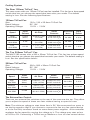
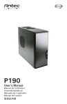
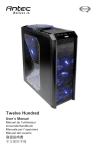
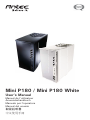
Mini P180 / Mini P180 White User’s Manual Manuel de l’utilisateur Anwenderhandbuch Manuale per l’operatore Manual del usuario পᡅ䂀ᯢ Ё᭛Փ⫼ݞ At Antec, we continually refine and improve our products to ensure the highest quality. As such your new case may differ slightly from the descriptions in this manual. This isn’t a problem; it’s simply an improvement. As of the date of publication, all features, descriptions, and illustrations in this manual are correct. Disclaimer This manual is intended only as a guide for Antec’s Computer Enclosures. For more comprehensive instructions on installing the motherboard and peripherals, please refer to the user’s manuals that come with those components. Mini P180 / Mini P180 White User’s Manual The Mini P180 is a small case that’s big on features. It is a professional case that is highly configurable. For that reason, this case comes without a power supply. Make sure you choose a power supply that conforms to the newest ATX standard and is compatible with your motherboard. Most ATX power supplies come with an on/off switch. Make sure you turn the switch to the ON (I) position before you boot up your computer for the first time. Normally, you won’t need to switch to the OFF (O) position, since the power supply includes a soft on/off feature. This lets you turn your computer on and off by using the soft switch on your computer case. If your computer crashes and you can’t shut it down using the soft switch, you can switch the main power to the OFF (O) position to clear the fault, then reboot. Setting Up 1. 2. 3. Place the case upright on a flat, stable surface with the rear of the case facing you. Remove the thumbscrews from the right side panel. Grip the panel at the top and bottom and slide it towards you to open the case. Remove the screws from the left side panel. Grip the panel at the top and bottom and slide it towards you to remove the left side panel. Note: Don’t use your fingernails to pry or lift the panels. Inside the case you should see two separate chambers — the upper chamber for motherboard, a 5.25” external drive and up to 5 hard drives; and the lower chamber for power supply and two bays for 5.25” external drives. The upper 5.25” bay will accommodate a CD or DVD drive up to 170mm in length. You will also find some wiring with marked connectors (USB, PWR etc.), drive rails for 5.25” drives, installed I/O panel, and a 5.25” to 3.5” drive bay adapter. Remove the middle hard disk cage to access the tool box which contains all the hardware screws, spare silicone grommets, and standoffs. Installing the power supply 1. 2. With the case upright, install the power supply into the case. Note: You can mount the power supply either side up. If you have a power supply with a large fan, the fan should be on top once the unit is installed. Between the two chambers a plastic structure lets you run cables between the upper and lower chambers. 1 Installing the Motherboard This manual does not cover CPU, RAM, or expansion card installation. Please consult your motherboard manual for specific mounting instructions and troubleshooting. 1. 2. 3. 4. 5. 6. Lay the case down, with the open side facing up. The drive cages and power supply area should be visible. Make sure you have the correct I/O panel for your motherboard. If the panel provided with the case isn’t suitable, please contact your motherboard manufacturer for the correct I/O panel. Line up the motherboard with the standoff holes. Determine which holes line up and remember where they are. Not all motherboards will match with all of the provided screw holes, and this is not necessary for proper functionality. Some standoffs may be pre-installed for your convenience. Remove your motherboard by lifting it up. Install standoffs as needed and put the motherboard back in. Screw in your motherboard to the standoffs with the provided Philips-head screws. Your motherboard is now installed. Cable Organizer Instead of running all the power cables into the upper chamber, they can be organized between the motherboard and right side panel. 1. 2. 3. 4. 5. Remove both side panels. Choose the cables you would like to pass through the holes behind the motherboard tray and pull them out of the power supply chamber towards the right side of the case. Route them up through the gap in the bar and use the cable ties to hold them in place. Feed the cables back through the insertion point nearest the destination of the cable. Connect the cable and then pull the slack back to the right side of the case. When finished, secure all cables with ties and put the right panel back in place. Connecting the Ports and LEDs 1. 2. 3. 4. Connect the Reset switch (labeled RESET SW) to your motherboard at the RST connector. Polarity (positive and negative) does not matter for switches. Power Switch (labeled POWER SW) connects to the PWR connector on the motherboard. Power LED (labeled POWER LED) connects to the PWR header on the motherboard. For LEDs, colored wires are positive (+). White or black wires are negative (–). If the LED does not light up when the system is powered on, try reversing the connection. For more info on connecting LEDs to your motherboard, see your motherboard manual. Hard Drive LED (labeled HDD LED) connects to the hard drive activity header. Connecting the USB Ports You will find a single 10-pin connector on a cable attached to the front USB ports. This Intel standard connector is keyed so that it can’t be accidentally reversed, as long as it is connected to a proper Intel standard motherboard header. Connect the 10-pin connector to your motherboard headers so that the blocked pin fits over the missing header pin. 2 Note: Please check your motherboard manual for your USB header pin layout and make sure it matches the table below. Motherboard Pin Layout 1 2 Pin 9 10 Signal Names Pin Signal Names 1 USB Power 1 2 USB Power 2 3 Negative Signal 1 4 Negative Signal 2 5 Positive Signal 1 6 Positive Signal 2 7 Ground 1 8 Ground 2 9 Key (No Connection) 10 Empty Pin Connecting the eSATA Port This case comes with an eSATA port in the front of the case to connect to your external SATA devices. You will find a SATA connector on a cable attached to the front eSATA ports. Connect it to a SATA connector on your motherboard. Connecting the Audio Ports (AC’97 and HDA) There is an Intel standard 10-pin AC’97 connector and an Intel 10-pin HDA (High Definition Audio) connector, you can connect either of them to your motherboard depending on the specification of the motherboard. See instruction below: Pin Assignment for Audio Ports (HDA and AC’97) 10 6 4 2 97531 Pin Signal Names (HDA) Pin Signal Names (AC’97) 1 MIC2 L 1 MIC In 2 AGND 2 GND 3 MIC2 R 3 MIC Power 4 AVCC 4 NC 5 FRO-R 5 Line Out (R) 6 MIC2_JD 6 Line Out (R) 7 F_IO_SEN 7 NC 8 Key (no pin) 8 Key (no pin) 9 FRO-L 9 Line Out (L) 10 LINE2_JD 10 Line Out (L) Note: Please check your motherboard manual for your audio header pin layout and make sure it matches the table. Even if your system supports both audio standards, you may only connect one connector, not both. Installing the Drives With the front bezel facing you, swing the front door out. It can swing 270 degrees so the door will be parallel with the side of the case. You can see one 5.25” external drive bay at the top and two 5.25” drive bays at the bottom of the 3 case. Inside the case there are two 3.5” drive cages located in the upper chamber, which can house up to five hard drives. Note: We recommend using the top 5.25” drive bay for your main 5.25” device. 5.25” Device Installation There are three 5.25” drive bays that need a pair of drive rails for each drive. The top 5.25” bay has a depth limitation of 170mm. Most new CD/DVD drives are not longer than 170mm, but older bigger drives will have to be installed in one of the lower two bays. 1. 2. 3. 4. 5. Carefully remove the plastic drive bay cover and the metal plate covering the drive bay. There is a hole in the metal plate that will allow you to insert a standard or Phillips screwdriver and rock the plate back and forth to break the connector points. Mount the drive rails onto the sides of the 5.25” device. Make sure the metal portion is angled towards the outside of the case. Slide the device into the drive bay until you hear a click. Mount the other devices accordingly. Hook up an appropriate connector from the power supply to the power connector on each of the devices. Upper HDD Installation 1. 2. 3. 4. 5. 6. 7. Remove the thumbscrew holding the upper HDD cage. Pull the HDD cage from its position by pulling the ring towards you. You can mount three hard drives inside the cage. They are mounted vertically with the silicone grommets sitting at both sides. Mount your hard drive into the drive cage with the special screws provided. Don’t over-tighten the screws, as this will reduce the vibration and noise dampening ability of the silicone grommets. Note: Always mount the HDD with the thicker side of the silicone grommets facing up. Slide the cage back into the case and fasten the thumbscrew. Find the right connector on the power supply and connect it to the hard drive. Repeat the same procedure for the other drives. Lower HDD Installation 1. 2. 3. 4. 5. 6. 7. 8. Remove the thumbscrew holding the lower HDD cage. Pull the HDD cage from its position by pulling the ring towards you. There are two HDD trays inside the cage. Squeeze the metal clips on each side of the tray and slide the tray out. Mount your hard drive into the drive tray with the special screws provided. Don’t over-tighten the screws as this will reduce the vibration and noise dampening ability of the silicone grommets. Note: Always mount the HDD with the thicker side of the silicone grommets facing up. Slide and lock the tray back into the cage. Slide the cage back to the case and fasten the thumbscrew. Find the right connector on the power supply and connect it to the hard drive. Repeat the same procedure for the other drives. 4 Cooling System The Rear 120mm TriCool™ fan: This case comes with one 120mm TriCool rear fan installed. This fan has a three-speed switch that lets you choose the speed that best suits your needs. The default setting is Low. See the following specifications. 120mm TriCool Fan Size: Rated Voltage: Operating Voltage: 120 x 120 x 25.4mm TriCool Fan DC 12V 10.2V ~ 13.8V Speed Input Current Air Flow Static Pressure Acoustical Noise Input Power High 2000 RPM 0.24A (Max.) 2.24 m³ / min (79 CFM) 2.54 mm-H2O (0.10 inch-H2O) 30 dBA 2.9 W Medium 1600 RPM 0.2A 1.59 m³ / min (56 CFM) 1.53 mm-H2O (0.06 inch-H2O) 28 dBA 2.4 W Low 1200 RPM 0.13A 1.1 m³ / min (39 CFM) 0.92 mm-H2O (0.04 inch-H2O) 25 dBA 1.6 W The Top 200mm TriCool™ Fan The Mini P180 comes with a 200 x 30mm TriCool fan. This fan has a three-speed switch that lets you choose the speed that best suits your needs. The default setting is Low. See the specification below: 200mm TriCool Fan Size: Rated Voltage: Operating Voltage: 200 x 200 x 30mm TriCool Fan DC 12V 10.2V ~ 13.8V Speed Input Current Air Flow Static Pressure Acoustical Noise Input Power High 800 RPM 0.3A (Max.) 3.799 m³ / min (134.11CFM) 0.688 mm-H2O (0.027 inch-H2O) 29.4 dBA 3.6 W Medium 600 RPM 0.17A 3.07 m³ / min (108.493 CFM) 0.397 mm-H2O (0.016 inch-H2O) 26.5 dBA 2.04 W Low 400 RPM 0.08A 2.34 m³ / min (82.612 CFM) 0.197mm-H2O (0.008 inch-H2O) 23.6 dBA 0.96 W The External fan Control: There are two external fan switches on the rear of the case near the top. They allow you to adjust the speed of these two fans without having to open the case. Note: The minimum voltage to start these fans is 5V. We recommend our users to set the fan speed to High if you choose to connect the fan to a fan control device or to the Fan-Only connector found on some Antec power supplies. A fan-controller regulates the fan speed by varying the voltage to it. The voltage may start as low as 4.5V to 5V. Connecting a TriCool set on Medium or Low to a fan-control device 5 may result in the fan not being able to start. The already lowered voltage from the fan controller will be further reduced by the TriCool circuitry below 5V. We recommend setting these fans to Low speed to maximize quiet computing. The Optional Fans There are two optional 120mm fan mounts at the front of the case inside the HDD cages. These two fan mounts are designed to enhance the CPU or VGA card cooling. However, you will need to remove the HDD cage (as a result of sacrificing two or three HDD bays depending on which cage to be removed) should you choose to use the fan mount in it. In order to build a quieter system we recommend NOT installing the optional fans. The Washable Air Filters There are two filters located behind the front grills and one filter inside the lower chamber. From time to time it will be necessary to wash the installed air filters. Not washing the air filters will result in higher system temperatures and possible stability problems. We recommend checking the air filters at least once a month initially. The frequency will depend on system usage (users whose systems run 24/7 will likely have to check/wash more often than those who don’t use their systems every day) and on environmental conditions. To remove the front filters: 1. 2. Push one of the fan grills at the right middle edge to open the grill . There are two tabs on the filter. To remove the filter use both your hands, grip the tabs and slide it towards the center, tag it outwards and lift out. To remove the bottom filter: 1. 2. Grasp the locking tab and gently push it towards the center of the filter. Tug the filter away from the case and then slide it out. For more useful suggestions and advice on building this case please visit Antec’s FAQ’s on www.antec.com 6 Antec, Inc. 47900 Fremont Blvd. Fremont, CA 94538 USA tel: 510-770-1200 fax: 510-770-1288 Antec Europe B.V. Stuttgartstraat 12 3047 AS Rotterdam The Netherlands tel: +31 (0) 10 462-2060 fax: +31 (0) 10 437-1752 Customer Support: US & Canada 1-800-22ANTEC [email protected] Europe +31 (0) 10 462-2060 [email protected] www.antec.com © Copyright 2008 Antec, Inc. All rights reserved. All trademarks are the property of their respective owners. Reproduction in whole or in part without written permission is prohibited. Printed in China.