1
PA-E3 and PA-2E3 Serial Port
Adapter
Description
The PA-E3 and PA-2E3 serial port adapters are available on Cisco 7200 series routers, on Cisco 7500
series routers, and on Cisco 7000 series routers with the 7000 Series Route Switch Processor
(RSP7000) and 7000 Series Chassis Interface (RSP7000CI). These port adapters provide one
(PA-E3) or two (PA-2E3) high-speed full-duplex synchronous serial E3 interfaces and integrated
data service unit (DSU) functionality.
The E3 port adapters can transmit and receive data at E3 rates of up to 34 Mbps and use a 75-ohm
coaxial cable available from Cisco to connect to a serial E3 network. These port adapters support the
following:
•
•
•
•
•
•
•
•
•
16- and 32-bit cyclic redundancy checks (CRC)
High-speed HDLC data
G.751 framing or bypass
HDB3 line coding
ATM-DXI, Frame Relay, HDLC, PPP, and SMDS serial encapsulation
National service bits
E3 MIB (RFC 1407)
Scrambling and reduced bandwidth
Remote and local loopbacks
Note For additional information on interoperability guidelines for E3 serial port adapter DSUs,
refer to the PA-E3 Serial Port Adapter Installation and Configuration publication.
Platforms
This feature is supported on these platforms:
•
•
•
Cisco 7200 series
Cisco 7500 series
Cisco 7000 series routers with the RSP7000 and RSP7000CI
PA-E3 and PA-2E3 Serial Port Adapter 1
Configuration Tasks
Configuration Tasks
Perform the tasks in the following sections to configure the PA-E3 (all tasks are optional except for
the first task):
•
•
•
Configure the PA-E3 Port Adapter
Troubleshoot the PA-E3 Port Adapter
Monitor and Maintain the PA-E3 Port Adapter
For PA-E3 port adapter configuration examples, see the “Configuration Example” section, later in
this chapter.
The PA-E3 supports most interface commands. For information about these commands, refer to the
“Configuring Interfaces” chapter of the Configuration Fundamentals Configuration Guide. For
additional information on how to configure the PA-E3 serial port adapter, refer to the “Configure a
Synchronous Serial Interface” section in the “Configuring Interfaces” chapter of the Configuration
Fundamentals Configuration Guide.
For information on other commands that can be used by the PA-E3 serial port adapter, refer to the
Cisco IOS Release 11.1 configuration guides.
Configure the PA-E3 Port Adapter
In addition to the commands in the “Configure a Synchronous Serial Interface” section in the
“Configuring Interfaces” chapter of the Configuration Fundamentals Configuration Guide, the
commands listed in Table 1 have been added to support the PA-E3 interface configuration.
If you do not modify the configuration of the PA-E3, the configuration defaults shown in Table 1 are
used.
Table 1
PA-E3 Port Adapter Defaults
Command
Default Value
dsu bandwidth
34010 kbps
dsu mode
0
framing
g751
international bit
00
invert data
data is not inverted
national bit
0
scramble
disabled
If you need to change any of the default configuration attributes, complete the first task in global
configuration mode followed by any of the optional tasks in interface configuration mode:
Task
Command
Select the PA-E3 interface and enter interface
configuration mode.
interface serial slot/port-adapter/port (Cisco 7500
series and Cisco 7000 series routers with the
RSP7000 and RSP7000CI)
interface serial slot/port (Cisco 7200 series)
Change the DSU bandwidth.
2 Release 11.1 CA
dsu bandwidth kbps
Configuration Tasks
Task
Command
Change the DSU mode. To connect to another
PA-E3 port adapter or a Digital Link DSU, use the
default mode (0). To connect to a Kentrox DSU, use
mode 1.
dsu mode {0 | 1}
Change the framing used by the interface.
framing {g751 | bypass}
Change the international bit used by the interface.
international bit {0 | 1} {0 | 1}
Invert the data stream on the interface.
invert data
Change the national bit used by the interface.
national bit {0 | 1}
Enable scrambling on the interface.
scramble
Troubleshoot the PA-E3 Port Adapter
To set the following loopbacks to troubleshoot the PA-E3 port adapter using Cisco IOS software,
perform the first task beginning in global configuration mode followed by any of the other tasks
depending on your needs:
Task
Command
Loopback after the LIU toward the terminal.
loopback dte
Loopback after going through the framer toward
the terminal.
loopback local
Loopback toward the network before going
through the framer.
loopback network line
Loopback toward the network after going through
the framer.
loopback network payload
These loopback commands loop all packets from the E3 interface back to the interface and also
direct the packets to the network.
Monitor and Maintain the PA-E3 Port Adapter
After configuring the new interface, you can display its status. To show current status of the E3
interface on the PA-E3 port adapter, perform any of the following tasks in EXEC mode:
Task
Command
Display statistics for the E3 interface.
show interfaces serial slot/port-adapter/port
(Cisco 7500 series and Cisco 7000 series routers
with the RSP7000 and RSP7000CI)
show interfaces serial slot/port (Cisco 7200 series)
Display the configuration information for the E3
interface.
show controllers serial slot/port-adapter/port
(Cisco 7500 series and Cisco 7000 series routers
with the RSP7000 and RSP7000CI)
show controllers serial slot/port (Cisco 7200
series)
PA-E3 and PA-2E3 Serial Port Adapter 3
Configuration Example
Configuration Example
The following example shows a typical configuration for serial interface 1/0/0 on a PA-E3 serial port
adapter in a Cisco 7500 series router. The dsu bandwidth command reduces the bandwidth by
padding the E3 frame, the dsu mode command enables and improves interoperability with other
DSUs, and the national bit command sets Bit 12 in the E3 frame to 1.
router# configure terminal
router(config)# interface serial 1/0/0
router(config-if)# ip address 1.1.1.10 255.255.255.0
router(config-if)# clock source internal
router(config-if)# crc 32
router(config-if)# dsu bandwidth 16000
router(config-if)# dsu mode 0
router(config-if)# national bit 1
router(config-if)# no scramble
router(config-if)# framing g751
router(config-if)# no shutdown
router(config-if)# exit
router(config)# exit
router#
Command Reference
This section documents new or modified commands. All other commands used with this feature are
documented in the Cisco IOS Release 11.1 command references.
•
•
•
•
•
•
•
•
•
•
•
•
4 Release 11.1 CA
clock source (interface)
dsu bandwidth
dsu mode
framing
international bit
invert data
loopback
national bit
scramble
show controllers serial
show diag
show interfaces serial
Command Reference
clock source (interface)
To control which clock a G.703 E1 interface, an E1-G.703/G.704 serial port adapter, or a PA-E3
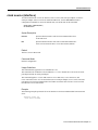
serial port adapter will use to clock its transmitted data from, use the clock source interface
configuration command. To restore the default value, use the no form of this command.
clock source {internal | line}
no clock source
Syntax Description
internal
Specifies that the interface will clock its transmitted data from
its internal clock.
line
Specifies that the interface will clock its transmitted data from a
clock recovered from the line’s receive data stream (default).
Default
The line’s receive data stream.
Command Mode
Interface configuration
Usage Guidelines
This command first appeared in Cisco IOS Release 10.3.
This command was modified in Cisco IOS Release 11.1 CA to include the E1-G.703/G.704 serial
port adapter and PA-E3 serial port adapter.
This command applies to a Cisco 4000 router or Cisco 7000 series, Cisco 7200 series, and
Cisco 7500 series router. A G.703-E1 interface, PA-E3 serial port adapter, or E1-G.703/G.704 serial
port adapter can clock its transmitted data from either its internal clock or from a clock recovered
from the line’s receive data stream.
Example
The following example specifies the G.703-E1 interface to clock its transmitted data from its internal
clock:
interface serial 1/0
clock source internal
PA-E3 and PA-2E3 Serial Port Adapter 5
Command Reference
dsu bandwidth
To specify the maximum allowable bandwidth used by the PA-E3 port adapter, use the dsu
bandwidth interface configuration command. To return to the default bandwidth, use the no form
of this command.
dsu bandwidth kbps
no dsu bandwidth
Syntax Description
kbps
Maximum bandwidth in the range of 22 kbps to 34010 kbps. The
default is 34010 kbps.
Default
34010 kbps
Command Mode
Interface configuration
Usage Guidelines
This command first appeared in Cisco IOS Release 11.1 CA.
The local interface configuration must match the remote interface configuration. For example, if you
reduce the maximum bandwidth to 16000 on the local port, you must also do the same on the remote
port.
The dsu bandwidth command reduces the bandwidth by padding the E3 frame.
To verify the data service unit (DSU) bandwidth configured on the interface, use the show controller
serial EXEC command.
Example
The following example sets the DSU bandwidth to 16000 kbps on interface 1/0/0:
interface serial 1/0/0
dsu bandwidth 16000
Related Command
show controllers serial
6 Release 11.1 CA
Command Reference
dsu mode
To specify the interoperability mode used by the PA-E3 port adapter, use the dsu mode interface
configuration command. To return to the default mode, use the no form of this command.
dsu mode {0 | 1}
no dsu mode
Syntax Description
0
Sets the interoperability mode to 0. This is the default. Specify mode 0
to connect the PA-E3 port adapter to another PA-E3 port adapter or to a
Digital Link DSU (DL3100).
1
Sets the interoperability mode to 1. Specify mode 1 to connect the
PA-E3 port adapter to a Kentrox DSU.
Default
0 mode
Command Mode
Interface configuration
Usage Guidelines
This command first appeared in Cisco IOS Release 11.1 CA.
The local interface configuration must match the remote interface configuration. For example, if you
define the data service unit (DSU) interoperability mode as 1 on the local port, you must also do the
same on the remote port.
You must know what type of DSU is connected to the remote port to determine if it interoperates
with the PA-E3 port adapter. Use mode 0 to connect a PA-E3 port adapter to another PA-E3 port
adapter or to a Digital Link DSU (DL3100). Use mode 1 to connect a PA-E3 port adapter to a
Kentrox DSU.
The dsu mode command enables and improves interoperability with other DSUs.
To verify the DSU mode configured on the interface, use the show controller serial EXEC
command.
Example
The following example sets the DSU mode to 1 on interface 1/0/0:
interface serial 1/0/0
dsu mode 1
Related Command
show controllers serial
PA-E3 and PA-2E3 Serial Port Adapter 7
Command Reference
framing
To specify E3 line framing used by the PA-E3 port adapter, use the framing interface configuration
command. To return to the default G.751 framing, use the no form of this command.
framing {bypass | g751}
no framing
Syntax Description
bypass
Specifies bypass E3 framing.
g751
Specifies G.751 E3 framing. This is the default.
Default
G.751 framing
Command Mode
Interface configuration
Usage Guidelines
This command first appeared in Cisco IOS Release 11.1 CA.
The default framing is described in the ITU-T Recommendation G.751.
Note The ITU-T carries out the functions of the former Consultative Committee for International
Telegraph and Telephone (CCITT).
When the framing mode is bypass, the E3 frame data is not included in the E3 frame, just the data.
To verify the framing mode configured on the interface, use the show controller serial EXEC
command.
Example
The following example sets the framing mode to bypass on interface 1/0/0:
interface serial 1/0/0
framing bypass
Related Command
show controllers serial
8 Release 11.1 CA
Command Reference
international bit
To set the E3 international bit in the G.751 frame used by the PA-E3 port adapter, use the
international bit interface configuration command. To return to the default international bit, use the
no form of this command.
international bit {0 | 1} {0 | 1}
no international bit
Syntax Description
0|1
Specifies the value of the first international bit in the G.751 frame. The
default is 0.
0|1
Specifies the value of the second international bit in the G.751 frame.
The default is 0.
Default
0 0 international bit
Command Mode
Interface configuration
Usage Guidelines
This command first appeared in Cisco IOS Release 11.1 CA.
The international bit command sets bits 6 and 8 respectively of set II in the E3 frame.
To verify the international bit configured on the interface, use the show controller serial EXEC
command.
Example
The following example sets the international bit to 1 1 on the PA-E3 port adapter in slot 1,
port-adapter slot 0, interface 0:
interface serial 1/0/0
international bit 1 1
Related Commands
national bit
show controllers serial
PA-E3 and PA-2E3 Serial Port Adapter 9
Command Reference
invert data
To invert the data stream, use the invert data interface configuration command. This command
applies only to the Cisco 7000 series routers with the RSP7000 and RSP7000CI, Cisco 7200 series
routers, and Cisco 7500 series routers. To disable this feature, use the no form of this command.
invert data
no invert data
Syntax Description
This command has no arguments or keywords.
Default
Data is not inverted.
Command Mode
Interface configuration
Usage Guidelines
This command first appeared in Cisco IOS Release 11.1 CA and Release 11.2 P.
If the interface on the PA-8T and PA-4T+ synchronous serial port adapters is used to drive a
dedicated T1 line that does not have B8ZS encoding (a method to avoid 15 zeros), the data stream
must be inverted (both TXD and RXD) either in the connecting CSU/DSU or the interface.
By inverting the HDLC data stream, the HDLC zero insertion algorithm becomes a ones insertion
algorithm that satisfies the T1 requirements. Be careful not to invert data both on the interface and
on the CSU/DSU as two data inversions will cancel each other out.
If the interface on the CT3IP uses AMI line coding, you must also invert the data on the T1 channel.
For more information, see the t1 linecode controller configuration command.
Example
The following example inverts data on serial interface 3/1/0:
interface serial 3/1/0
invert data
10 Release 11.1 CA
Command Reference
loopback
To loop the serial interface on a PA-E3 port adapter, use the loopback interface configuration
command. To remove the loopback, use the no form of this command.
loopback {dte | local | network {line | payload}}
no loopback
Syntax Description
dte
Sets the loopback after the LIU toward the terminal.
local
Sets the loopback after going through the framer toward the
terminal.
network {line | payload}
Sets the loopback toward the network before going through the
framer (line) or after going through the framer (payload).
Default
Disabled
Command Mode
Interface configuration
Usage Guidelines
This command first appeared in Cisco IOS Release 11.1 CA.
Use this command for troubleshooting purposes.
To verify that a loopback is configured on the interface, use the show interface serial or show
interfaces loopback EXEC command.
Example
The following example configures the serial interface located in slot 3/0/0 for a local loopback:
interface serial 3/0/0
loopback local
Related Command
show interfaces serial
PA-E3 and PA-2E3 Serial Port Adapter 11
Command Reference
national bit
To set the E3 national bit in the G.751 frame used by the PA-E3 port adapter, use the national bit
interface configuration command. To return to the default E3 national bit, use the no form of this
command.
national bit {0 | 1}
no national bit
Syntax Description
0|1
Specifies the E3 national bit in the G.751 frame. The default is 0.
Default
0 national bit
Command Mode
Interface configuration
Usage Guidelines
This command first appeared in Cisco IOS Release 11.1 CA.
The national bit command sets Bit 12 in the E3 frame.
To verify the national bit configured on the interface, use the show controller serial EXEC
command.
Example
The following example sets the national bit to 1 on the PA-E3 port adapter in slot 1, port adapter slot
0, interface 0:
interface serial 1/0/0
national bit 1
Related Commands
international bit
show controllers serial
12 Release 11.1 CA
Command Reference
scramble
To enable scrambling of the payload on the PA-E3 port adapter, use the scramble interface
configuration command. To disable scrambling, use the no form of this command.
scramble
no scramble
Syntax Description
This command has no keywords and arguments.
Default
Scrambling is disabled.
Command Mode
Interface configuration
Usage Guidelines
This command first appeared in Cisco IOS Release 11.1 CA.
E3 scrambling is used to assist clock recovery on the receiving end.
Scrambling can prevent some bit patterns from being mistakenly interpreted as alarms by switches
placed between the DSUs.
The local interface configuration must match the remote interface configuration. For example, if you
enable scrambling on the local port, you must also do the same on the remote port.
To verify that scramble is configured on the interface, use the show controllers serial EXEC
command.
Example
The following example enables scrambling on the PA-E3 port adapter in slot 1, port adapter slot 0,
interface 0:
interface serial 1/0/0
scramble
Related Command
show controllers serial
PA-E3 and PA-2E3 Serial Port Adapter 13
Command Reference
show controllers serial
Use the show controllers serial privileged EXEC command to display information that is specific
to the interface hardware.
show controllers serial [slot/port]
show controllers serial [slot/port-adapter/port] (Cisco 7500 series and Cisco 7000 series routers with
the RSP7000 and RSP7000CI)
Syntax Description
slot
(Optional) Slot number of the interface.
port
(Optional) Port number on the interface. The port value is always 0.
port-adapter
(Optional) On Cisco 7500 series routers and Cisco 7000 series routers
with the RSP7000 and RSP7000CI, the location of the port adapter on
a VIP card. The value can be 0 or 1.
Command Mode
Privileged EXEC
Usage Guidelines
This command first appeared in Cisco IOS Release 10.0.
This command was modified in Cisco IOS Release 11.1 CA to include sample output for the PA-E3
port adapter.
The information displayed is generally useful for diagnostic tasks performed by technical support
personnel only. For the PA-E3, the show controllers serial command also displays configuration
information such as the framing, clock source, bandwidth limit, whether scrambling is enabled, the
national bit, the international bits, and DSU mode configured on the interface. Also displayed is the
performance statistics for the current interval and last 15-minute interval and whether any alarms
exist.
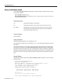
Sample Display
The following is sample output from the show controllers serial command for a PA-E3 serial port
installed in slot 2:
router# show controllers serial 2/0
M1T-E3 pa: show controller:
PAS unit 0, subunit 0, f/w version 2-55, rev ID 0x2800001, version 2
idb = 0x6080D54C, ds = 0x6080F304, ssb=0x6080F4F4
Clock mux=0x30, ucmd_ctrl=0x0, port_status=0x1
Serial config=0x8, line config=0x1B0202
maxdgram=4474, bufpool=128Kb, 256 particles
rxLOS inactive, rxLOF inactive, rxAIS inactive
txAIS inactive, rxRAI inactive, txRAI inactive
line state: up
E3 DTE cable, received clockrate 50071882
base0 registers=0x3D000000, base1 registers=0x3D002000
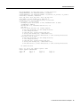
14 Release 11.1 CA
Command Reference
mxt_ds=0x608BA654, rx ring entries=128, tx ring entries=256
rxring=0x4B01F480, rxr shadow=0x6081081C, rx_head=26
txring=0x4B01F960, txr shadow=0x60810E48, tx_head=192, tx_tail=192, tx_count=0
throttled=0, enabled=0, disabled=0
rx_no_eop_err=0, rx_no_stp_err=0, rx_no_eop_stp_err=0
rx_no_buf=0, rx_soft_overrun_err=0, dump_err= 1
tx_underrun_err=0, tx_soft_underrun_err=0, tx_limited=0
tx_fullring=0, tx_started=11504
Framing is g751, Clock Source is Line, Bandwidth limit is 34010.
Scrambling is enabled
National Bit is 0, Internaltional Bits are: 0 0
DSU mode 1
Data in current interval (213 seconds elapsed):
0 Line Code Violations, 0 P-bit Coding Violation
0 C-bit Coding Violation
0 P-bit Err Secs, 0 P-bit Severely Err Secs
0 Severely Err Framing Secs, 0 Unavailable Secs
0 Line Errored Secs, 0 C-bit Errored Secs, 0 C-bit Severely Errored Secs
Total Data (last 24 hours)
0 Line Code Violations, 0 P-bit Coding Violation,
0 C-bit Coding Violation,
0 P-bit Err Secs, 0 P-bit Severely Err Secs,
0 Severely Err Framing Secs, 0 Unavailable Secs,
0 Line Errored Secs, 0 C-bit Errored Secs, 0 C-bit Severely Errored Secs
No alarms detected.
PIO A:
Framer
reg 0:
reg 4:
639, PIO
register
E0
0
B: 303, Gapper register: 50DE
information:
reg 1: 0
reg 2: 0
reg 5: 8
reg 6: 0
reg 3: 0
reg 7: 0
PA-E3 and PA-2E3 Serial Port Adapter 15
Command Reference
show diag
To display hardware information for an interface, use the show diag privileged EXEC command on
Cisco 7500 series routers.
show diag [slot]
Syntax Description
slot
(Optional) Slot number of the interface.
Command Mode
Privileged EXEC
Usage Guidelines
This command first appeared in Cisco IOS Release 11.1 CA.
Use this command to determine the type of port adapter installed on a VIP2 in your router.
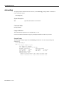
Sample Display
The following is sample output from the show diag command for a PA-E3 serial port adapter in
chassis slot 2:
byron# show diag 2
Slot 2:
E3 PA port adapter, 1 port
Port adapter is analyzed
Port adapter insertion time 1w0d ago
Hardware revision 0.1
Board revision
Serial number
4509983
Part number
Test history
0x0
RMA number
EEPROM format version 0
EEPROM contents (hex):
0x20: 00 71 00 01 00 44 D1 1F 49 0A 3C 02 00
0x30: 01 00 00 00 97 06 12 00 FF FF FF FF FF
16 Release 11.1 CA
A0
73-2620-02
00-00-00
00 00 00
FF FF FF
Command Reference
show interfaces serial
To display information about a serial interface, use the show interfaces serial privileged EXEC
command.
show interfaces serial [slot/port] (Cisco 7200 series)
show interfaces serial [slot/port-adapter/port] (Cisco 7500 series and Cisco 7000 series with
the RSP7000 and RSP7000CI)
Syntax Description
slot
(Optional) Slot number of the interface.
port
(Optional) Port number on the interface. The port value is always 0.
port-adapter
(Optional) On Cisco 7500 series routers and Cisco 7000 series routers with
the RSP7000 and RSP7000CI, the location of the port adapter on a VIP
card. The value can be 0 or 1.
Command Mode
Privileged EXEC
Usage Guidelines
This command was modified in Cisco IOS Release 11.1 CA to include sample output for the PA-E3
serial port adapter.
For additional command syntax and sample displays, refer to the show interfaces serial command
in the “Interface Commands” chapter of the Configuration Fundamentals Command Reference.
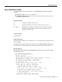
Sample Displays
The following is sample output from the show interfaces command for a PA-E3 serial port adapter
installed in chassis slot 2:
Router# show interfaces serial 2/0
Serial2/0 is up, line protocol is up
Hardware is M1T-E3 pa
Internet address is 131.1.1.1/24
MTU 4470 bytes, BW 34010 Kbit, DLY 200 usec, rely 128/255, load 1/255
Encapsulation HDLC, loopback not set, keepalive not set
Last input 1w0d, output 00:00:48, output hang never
Last clearing of “show interface” counters 1w0d
Queueing strategy: fifo
Output queue 0/40, 0 drops; input queue 0/75, 0 drops
5 minute input rate 0 bits/sec, 0 packets/sec
5 minute output rate 0 bits/sec, 0 packets/sec
20 packets input, 2080 bytes, 0 no buffer
Received 0 broadcasts, 0 runts, 0 giants, 0 parity
0 input errors, 0 CRC, 0 frame, 0 overrun, 0 ignored, 0 abort
11472 packets output, 3824748 bytes, 0 underruns
0 output errors, 0 applique, 0 interface resets
0 output buffer failures, 0 output buffers swapped out
0 carrier transitions
rxLOS inactive, rxLOF inactive, rxAIS inactive
txAIS inactive, rxRAI inactive, txRAI inactive
PA-E3 and PA-2E3 Serial Port Adapter 17
Command Reference
Table 2 describes significant fields shown in the display.
Table 2
Show Interfaces Serial Field Descriptions
Field
Description
Serial... is {up | down}
...is administratively down
Indicates whether the interface hardware is currently active (whether
carrier detect is present), inactive, or has been taken down by an
administrator.
line protocol
is {up | down}
Indicates whether the software processes that handle the line protocol
consider the line usable (that is, whether keepalives are successful) or
if it has been taken down by an administrator.
Hardware is
Specifies the hardware type.
Internet address is
Specifies the Internet address and subnet mask.
MTU
Maximum Transmission Unit of the interface.
BW
Indicates the value of the bandwidth parameter that has been
configured for the interface (in kilobits per second). The bandwidth
parameter is used to compute IGRP metrics only. If the interface is
attached to a serial line with a line speed that does not match the
default (1536 or 1544 for T1 and 56 for a standard synchronous serial
line), use the bandwidth command to specify the correct line speed
for this serial line.
DLY
Delay of the interface in microseconds.
rely
Reliability of the interface as a fraction of 255 (255/255 is 100%
reliability), calculated as an exponential average over 5 minutes.
load
Load on the interface as a fraction of 255 (255/255 is completely
saturated), calculated as an exponential average over 5 minutes.
Encapsulation
Encapsulation method assigned to interface.
loopback
Indicates whether loopback is set or not.
keepalive
Indicates whether keepalives are set or not.
Last input
Number of hours, minutes, and seconds since the last packet was
successfully received by an interface. Useful for knowing when a dead
interface failed.
Last output
Number of hours, minutes, and seconds since the last packet was
successfully transmitted by an interface.
output hang
Number of hours, minutes, and seconds (or never) since the interface
was last reset because of a transmission that took too long. When the
number of hours in any of the “last” fields exceeds 24 hours, the
number of days and hours is printed. If that field overflows, asterisks
are printed.
Last clearing of “show interface”
counters
Time the counters were last cleared.
Queueing strategy
First-in, first-out queuing strategy (other queueing strategies you
might see are priority-list, custom-list, and weighted fair).
Output queue, drops
Number of packets in output and input queues. Each number is
followed by a slash, the maximum size of the queue, and the number
of packets dropped due to a full queue.
input queue, drops
18 Release 11.1 CA
Command Reference
Table 2
Show Interfaces Serial Field Descriptions (Continued)
Field
Description
5 minute input rate
Average number of bits and packets transmitted per second in the last
5 minutes.
5 minute output rate
The 5-minute input and output rates should be used only as an
approximation of traffic per second during a given 5-minute period.
These rates are exponentially weighted averages with a time constant
of 5 minutes. A period of four time constants must pass before the
average will be within two percent of the instantaneous rate of a
uniform stream of traffic over that period.
packets input
Total number of error-free packets received by the system.
bytes input
Total number of bytes, including data and MAC encapsulation, in the
error free packets received by the system.
no buffers
Number of received packets discarded because there was no buffer
space in the main system. Compare with ignored count. Broadcast
storms on Ethernets and bursts of noise on serial lines are often
responsible for no input buffer events.
Received... broadcasts
Total number of broadcast or multicast packets received by the
interface.
runts
Number of packets that are discarded because they are smaller than
the medium’s minimum packet size.
giants
Number of packets that are discarded because they exceed the
medium’s maximum packet size.
parity
Number of the parity errors on the interface.
input error
Total number of no buffer, runts, giants, CRCs, frame, overrun,
ignored, and abort counts. Other input-related errors can also
increment the count, so that this sum might not balance with the other
counts.
CRC
Cyclic redundancy checksum generated by the originating station or
far-end device does not match the checksum calculated from the data
received. On a serial link, CRCs usually indicate noise, gain hits, or
other transmission problems on the data link.
frame
Number of packets received incorrectly having a CRC error and a
noninteger number of octets. On a serial line, this is usually the result
of noise or other transmission problems.
overrun
Number of times the serial receiver hardware was unable to hand
received data to a hardware buffer because the input rate exceeded the
receiver’s ability to handle the data.
ignored
Number of received packets ignored by the interface because the
interface hardware ran low on internal buffers. Broadcast storms and
bursts of noise can cause the ignored count to be increased.
abort
Illegal sequence of one bits on a serial interface. This usually indicates
a clocking problem between the serial interface and the data link
equipment.
packets output
Total number of messages transmitted by the system.
bytes output
Total number of bytes, including data and MAC encapsulation,
transmitted by the system.
underruns
Number of times that the transmitter has been running faster than the
router can handle. This might never be reported on some interfaces.
PA-E3 and PA-2E3 Serial Port Adapter 19
Supported MIB
Table 2
Show Interfaces Serial Field Descriptions (Continued)
Field
Description
output errors
Sum of all errors that prevented the final transmission of datagrams
out of the interface being examined. Note that this might not balance
with the sum of the enumerated output errors, as some datagrams
might have more than one error, and others might have errors that do
not fall into any of the specifically tabulated categories.
applique
Indicates an unrecoverable error has occurred on the E3 applique. The
router then invokes an interface reset.
interface resets
Number of times an interface has been completely reset. This can
happen if packets queued for transmission were not sent within several
seconds’ time. On a serial line, this can be caused by a malfunctioning
modem that is not supplying the transmit clock signal, or by a cable
problem. If the system notices that the carrier detect line of a serial
interface is up, but the line protocol is down, it periodically resets the
interface in an effort to restart it. Interface resets can also occur when
an interface is looped back or shut down.
output buffer failures
Number of no resource errors received on the output.
output buffers swapped out
Number of packets swapped to DRAM.
carrier transitions
Number of times the carrier detect signal of a serial interface has
changed state. For example, if data carrier detect (DCD) goes down
and comes up, the carrier transition counter will increment two times.
Indicates modem or line problems if the carrier detect line is changing
state often.
rxLOS, rxLOF, rxAIS
Receive loss of signal, loss of frame, and alarm indication signal
status. Values are inactive or active.
txAIS, rxRAI, txRAI
Transmit alarm indication signal, receive remote alarm indicator, and
transmit remote alarm indicator status. Values are inactive or active.
When the router receives an LOS, LOF, or AIS, the txRAI is active.
When the remote router receives an LOS, LOF, or AIS, the rxRAI is
active.
Supported MIB
The PA-E3 port adapter supports a subset of RFC 1407 MIB.
We support DS3 Near End Group including—DS3/E3 Configuration Table, DS3/E3 Current Table,
DS3/E3 Interval Table, and DS3/E3 Total Table.
We do not support DS3 Far End Group and DS3/E3 Fractional Group.
The PA-E3 port adapter also supports the cardTable in the Cisco Chassis MIB and the MIB-2 for
each PA-E3 interface.
What to Do Next
For more information on the PA-E3 serial port adapter, refer to the PA-E3 Serial Port Adapter
Installation and Configuration publication.
20 Release 11.1 CA