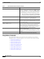
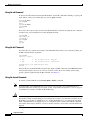
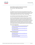
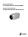
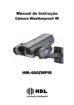
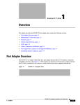
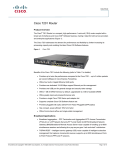
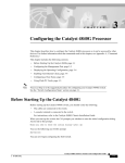
1
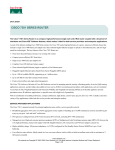
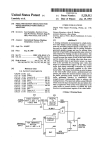
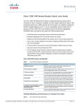
Using the Flash Disk
Product Numbers: MEM-I/O-FLD64M=, MEM-I/O-FLD128M=, MEM-7100-FLD48M=, MEM-7100-FLD128M=,
MEM-7201-FLD256=, MEM-COMP-FLD64M=, MEM-COMP-FLD128M=, MEM-NPE-G1-FLD64=,
MEM-NPE-G1-FLD128=, MEM-NPE-G1-FLD256=, MEM-NPE-G2-FLD256=, MEM-RSP8-FLD48M(=),
MEM-RSP8-FLD64M(=), MEM-RSP8-FLD128M(=), MEM-RSP16-FLD48M(=), MEM-RSP16-FLD64M(=),
MEM-RSP16-FLD128M(=)
Document Revision History
The Document Revision History beginning with online part number OL-6452-02, records technical
changes in this document.
Document Version
Date
Notes
OL-6452-04
April, 2007
This version adds Cisco 7201 support.
OL-6452-03
May, 2006
This version adds NPE-G2.
OL-6452-02
September 8, 2005
This version removes the-end of-sale
MEM-I/O-D-FLD48M product identification from the
document. A section on Flash Disk OIR has also been
added.
Introduction
This document provides instructions for installing, removing, and using Flash Disks in Cisco 7100,
Cisco 7200 (including Cisco 7201), and Cisco 7500 products that have PC Card slots—formerly called
Personal Computer Memory Card International Association (PCMCIA) slots. (For a list of Cisco
products that support the Flash Disk—and how they support it—see the “Hardware Requirements”
section on page 3).
Flash Disks and the CompactFlash Disk provide storage space for your configuration files, Cisco IOS
software images, and so forth. (Also see the “Product Description” section on page 9.)
Americas Headquarters:
Cisco Systems, Inc., 170 West Tasman Drive, San Jose, CA 95134-1706 USA
© 2007 Cisco Systems, Inc. All rights reserved.
Contents
Contents
This configuration note includes the following sections:
•
Related Documentation, page 2
•
Installation Prerequisites, page 2
•
Safety Guidelines, page 8
•
Product Description, page 9
•
Installing a Flash Disk, page 10
•
Working with a Flash Disk, page 16
•
Obtaining Documentation, Obtaining Support, and Security Guidelines, page 25
Related Documentation
Your Cisco router and the Cisco IOS software running on it contain extensive features and functionality,
which are documented online and in the following resources:
•
Note
Cisco IOS software configuration documentation contains Cisco IOS software configuration
information and support. See the modular configuration and modular command reference
publications in the set that correspond to the software release installed on your Cisco hardware.
Access these documents at http://www.cisco.com.
You can access Cisco IOS software configuration and hardware installation and maintenance
documentation on the World Wide Web at http://www.cisco.com. Translated documentation is available
at the following URL: http://www.cisco.com/public/countries_languages.shtml
Translated documentation is available at the following URL:
http://www.cisco.com/public/countries_languages.shtml
For hardware installation and maintenance information, regulatory compliance and safety information,
and troubleshooting information, refer to the following documents:
•
Cisco 7100 Series Documentation
•
Cisco 7200 Series Routers Documentation Roadmap
•
Cisco 7500 Series Routers Documentation Roadmap
Installation Prerequisites
This section describes installation prerequisites you should observe before you can use the Flash Disk
or CompactFlash Disk in your system, and includes the following subsections:
•
Software Requirements, page 3
•
Hardware Requirements, page 3
•
Tools and Parts Required, page 4
•
Compatibility Requirements, page 4
•
System Memory and Software Image Functions and Interactions, page 5
Using the Flash Disk
2
OL-6452-04
Installation Prerequisites
•
Boot Environment Variables, page 6
•
Sample Upgrade Process, page 7
Software Requirements
The Flash Disk provides file storage for the Cisco products listed in the section “Hardware
Requirements” if these systems are running the applicable Cisco IOS release listed in Table 1, Table 2,
or a later release.
Table 1
Minimum Supported Cisco IOS Release for the Flash Disk
Platform
Minimum Supported Cisco IOS Release or a Later Release
Cisco 7120 and Cisco 7140 routers
12.0(4)XE, 12.0(7)T, 12.1(1)E, 12.1(1)
Cisco 7200 series routers using the
I/O controller
12.0(2)XE, 12.0(3)T, 12.0(5)S, 12.1(1)E, 12.1(1)T, 12.1(1),
12.2(1), 12.2(4)B
Cisco 7201 router
12.4(4)XD7, 12.2(31)SB5
Cisco 7500 series routers using RSP8 12.0(5)T, 12.0(9)S, 12.1(0), 12.1(2)E
Table 2
Minimum Supported IOS Release for the CompactFlash Disk
Platform
Minimum Supported Cisco IOS Release or Later Release
Cisco 7200 VXR router with NPE-G1 12.2.(4)BX
Using the Flash Disk requires that you upgrade the boot image to Cisco IOS Release 12.0(2) or a later
release of 12.0. Refer to the “Sample Upgrade Process” section on page 7 for upgrade instructions. (For
additional information regarding boot image requirements, see the “Compatibility Requirements”
section on page 4.)
Hardware Requirements
You can use a CompactFlash Disk for file storage on the NPE-G1 or NPE-G2 used in the
Cisco 7200 VXR routers, and the Cisco 7201. You must use a CompactFlash Disk for Cisco IOS software
configuration file storage.
You can use the Flash Disk for file storage in the PC Card slots of the Input/output (I/O) controller used
in Cisco 7200 series systems (Cisco 7202, Cisco 7204, Cisco 7204VXR, Cisco 7206, and
Cisco 7206VXR) and Cisco uBR7200 series universal broadband routers.
Note
The 48-MB, 64-MB, and 128-MB Flash Disk are not supported with the NPE-100, NPE-150, or
NPE-200 in a Cisco 7200 series system router or Cisco uBR7200 series universal broadband
router.
•
Cisco 7100 series systems—Cisco 7120 series routers and Cisco 7140 series routers
•
Route Switch Processor (RSP8)—Used in Cisco 7500 series systems (Cisco 7505, Cisco 7507,
Cisco 7507-MX, Cisco 7513, Cisco 7513-MX, and Cisco 7576)
Using the Flash Disk
OL-6452-04
3
Installation Prerequisites
For convenience throughout this publication, the I/O controller, Route Switch Module (RSM), network
processing engine (NPE), and RSP8 are referred to as the system processor. Specific differences are
clearly noted.
Tools and Parts Required
You need some or all of the following tools and parts to install a Flash Disk:
•
3/16-inch flat-blade screwdriver—For Flash Disk installation in Cisco 7100 series systems only
•
Antistatic wrist strap
•
Access to a Trivial File Transfer Protocol (TFTP) server
•
Linear Flash memory card
•
One of the following Flash Disk or CompactFlash Disk kits:
– Cisco 7100 series systems—Flash Disk Product Numbers: MEM-7100-FLD48M= or
MEM-7100-FLD128M= (See the “Hardware Requirements” section on page 3 for a system
list.)
– Cisco 7200 VXR routers
•
with the NPE-G2—CompactFlash Disk Product Number: MEM-NPE-G2-FLD256=
•
with the NPE-G1—CompactFlash Disk Product Numbers: MEM-NPE-G1-FLD64=,
MEM-NPE-G1-FLD128=,or MEM-NPE-G1-FLD256=
(See the “Hardware Requirements” section on page 3 for a system list.)
– Cisco 7200 series routers (I/O controller-based systems)—Flash Disk Product Numbers:
MEM-I/O-FLD48M=, MEM-I/O-FLD64M=, or MEM-I/O-FLD128M=
(See the “Hardware Requirements” section on page 3 for a system list.)
– Cisco 7500 series routers—Flash Disk Product Numbers MEM-RSP8-FLD48M=,
MEM-RSP8-FLD64M=, and MEM-RSP8-FLD12M8= for use with an RSP8 only, and
MEM-RSP16-FLD48M=, MWEM-RSP16-FLD64M=, and MEM-RSP16-FLD128M= for use
with an RSP16 only. (See the “Hardware Requirements” section on page 3 for a system list.)
Compatibility Requirements
This section discusses Flash Disk compatibility and use between supported systems.
In order to boot a Cisco IOS software image from the Flash Disk, when the system is executing from the
ROM monitor software image, your ROM monitor software image and your boot image must be from
one of the minimum Cisco IOS releases listed in Table 1. Use the show version or show hardware
commands to verify that your RSP8-based system is running these software images. The NPE-300 or
later version installed in the Cisco 7204VXR and Cisco 7206VXR systems and the Cisco 7201 meets
these requirements.
The format command places a processor-specific library on the Flash Disk so that the ROM monitor
software can read the Flash memory media. If you plan to use the boot or dir commands at the ROM
monitor prompt (rommon>), you might need to reformat your Flash Disk if it was not already formatted
on a like system processor.
Using the Flash Disk
4
OL-6452-04
Installation Prerequisites
Note
Formatting an Cisco 7500 series routers RSP-8 Flash Disk on any other RSP causes the Flash Disk to
not work on the RSP8. The same is true for an RSP16 Flash Disk. You must format a Flash Disk only on
the router with the RSP that you plan to use with the Flash Disk.
To ensure Flash Disk system compatibility, observe the following guidelines:
•
To use a Flash Disk from an I/O controller-based system in a Cisco 7500 series router RSP8-based
system, first reformat the Flash Disk on a system with an RSP-8 installed. Using another RSP to
format the disk causes the disk to not operate with an RSP8.
•
To use a Flash Disk from a Cisco 7500 series router RSP8-based system in an I/O controller-based
system, first reformat the Flash Disk on an RSP-8 system. Using another RSP to format the disk
causes the disk to not operate with an RSP8.
•
To use a Flash Disk from an I/O controller-based system in a Cisco 7500 series router RSP16-based
system, first reformat the Flash Disk on a system with an RSP-16 installed. Using another RSP to
format the disk causes the disk to not operate with an RSP16.
•
To use a Flash Disk from a Cisco 7500 series router RSP16-based system in an I/O controller-based
system, first reformat the Flash Disk on an RSP-16 system. Using another RSP to format the disk
causes the disk to not operate with an RSP16.
For simple file storage and retrieval functions, Flash Disks can be interchanged between and used in any
system listed in the “Hardware Requirements” section on page 3.
Note
The Flash Disk is supported as the primary boot medium for the RSP8-, NPE-300-, and later-based
systems only. In all other systems, you should use the Flash Disk side by side with a linear Flash memory
card. In systems using a Flash Disk with a linear Flash memory card, it is possible to boot from a Flash
Disk; however, you must maintain a bootable image on a linear Flash memory card to ensure that your
system is bootable if the boot flash memory software image becomes corrupted.
System Memory and Software Image Functions and Interactions
The read-only memory (ROM) monitor image on your system performs important functions, such as
running a brief set of system diagnostics, and initializing the hardware. This image gains control at reset
or power on, or after a nonrecoverable event (such as a bus error). The ROM monitor software image has
a rudimentary user interface that is recognizable by way of the ROM monitor prompt (rommon>). The
ROM monitor software image has console drivers and trap handlers for parity and bus errors; however,
the ROM monitor does not have any network interface code and it cannot boot an image over the
network.
Note
The ROM monitor is only able to load an image from boot flash memory, linear Flash memory cards, or
a Flash Disk (in RSP8-, NPE-300-, and later-based systems only).
By default, and as a result of a reset or power on, the ROM monitor loads the boot image from boot flash
memory. If the ROM monitor cannot find a bootable image in boot flash memory, it searches the PC
Card-based devices (such as linear Flash memory cards or Flash Disks) for the first bootable image.
Normally, this would be the boot image (such as rsp-boot-mz or c7200-boot-mz).
Using the Flash Disk
OL-6452-04
5
Installation Prerequisites
The boot image, when loaded, looks in the boot environment variables—stored in nonvolatile
random-access memory (NVRAM)—to determine the location of the Cisco IOS software image and the
configuration to use. If boot environment variables are not defined, the system will boot the first image
found on a Flash Disk, or if no such image is found, it will boot the first image found on a linear Flash
memory card.
The operation of the boot environment variables is described in the “Boot Environment Variables”
section, which follows.
Boot Environment Variables
The contents of the boot environment variables, which are stored in the configuration file in NVRAM,
determine the actions your system takes on bootup. To see the current settings of these variables, use the
show bootvar command as follows:
Router> show bootvar
BOOT variable =
CONFIG_FILE variable =
Current CONFIG_FILE variable =
BOOTLDR variable does not exist
Configuration register is 0x100
Following are explanations for each of these boot environment variables:
•
BOOT variable—Points to the Cisco IOS software image that you want to boot; you set it in
configuration mode. The default software image is the CISCOxxx image (where xxx is a filename
assigned by the system, if you do not enter a specific filename). The system then looks for the first
image on the Flash Disk in slot 0.
Enter configuration mode and specify a filename and PC Card slot from which to boot using the
configure terminal and boot system commands as follows:
Router# configure terminal
Enter configuration commands, one per line. End with CTRL-Z.
System(config)# boot system flash disk0:rsp-p-mz.12-0
The result of this configuration file entry is that the BOOT variable is disk0:rsp-p-mz.12-0.
•
CONFIG_FILE (configuration file) variable—Determines where the configuration is read from on
bootup; you set it in configuration mode as follows:
Router# configure terminal
Enter configuration commands, one per line. End with CTRL-Z.
System(config)# boot config disk0:configfile
The result of this configuration file entry is that the CONFIG_FILE variable is disk0:configfile.
•
BOOTLDR (boot loader) variable—Determines which image is used as the boot helper (boot
image); you set it in configuration mode as follows:
Router# configure terminal
Enter configuration commands, one per line. End with CTRL-Z.
System(config)# boot bootldr bootflash:c7200-boot-mz
The result of this configuration file entry is that the BOOTLDR variable is
bootflash:c7200-boot-mz.
•
Configuration register variable—Instructs the system where to look for a bootable Cisco IOS
software image; you set it as a hexadecimal value in configuration mode as follows:
Router# configure terminal
Enter configuration commands, one per line. End with CTRL-Z.
Using the Flash Disk
6
OL-6452-04
Information About Flash Disk OIR
System(config)# config-register 0x102
The result of this configuration file entry is that the configuration register is set to hexadecimal
0x102. Please see the Cisco 7200 VXR Installation and Configuration Guide (Chapter 4, “Observing
System Startup and Performing a Basic Configuration”) at
http://www.cisco.com/univercd/cc/td/doc/product/core/7200vx/72vxicg/configvx.htm for more
information about the configuration register.
Sample Upgrade Process
This section applies to users who want to use Flash Disks for simple file storage.
Step 1
Format your onboard Flash memory—called boot flash memory. (See the format command description
in the “Software Command Overview” section on page 16.)
Step 2
Upgrade your onboard Flash memory by copying the Cisco IOS Release 12.x boot image (such as
c7200-boot-mz) into onboard Flash memory. (See the “Using the copy Command” section on page 21.)
Step 3
Copy the Release 12.x software image from onboard Flash memory to the linear Flash memory card in
your system processor’s PC Card slot. (See the “Using the copy Command” section on page 21.)
Step 4
Change the boot variables in your configuration file to point to the new Cisco IOS image in your linear
Flash memory card. (See the preceding section, “Boot Environment Variables,” and the “Making a Flash
Disk-Based Software Image the Bootable Software Image” section on page 25.)
Step 5
Reboot your system to load the Release 12.x software image from the linear Flash memory card in your
system processor.
Step 6
Insert a Flash Disk. (See the “Installing a Flash Disk” section on page 10.)
Step 7
With your system running Cisco IOS release 12.x, format the blank Flash Disk. (See the format
command description in Table 5 on page 17, and the “Using the format Command” section on page 20.)
You should now be able to store configuration files and Cisco IOS software images on your Flash Disk.
If you have an NPE-300-based system (or a later processor), you should now be able to boot from any
Cisco IOS software images you store on your Flash Disk.
Note
To boot from Cisco IOS software images stored on a Flash Disk in an NPE-300-based system (or a later
processor), you must first copy the appropriate Cisco IOS software image to the Flash Disk. (See the
“Using the copy Command” section on page 21, the “Enabling Booting from a Flash Disk” section on
page 24, and the “Making a Flash Disk-Based Software Image the Bootable Software Image” section on
page 25.)
Information About Flash Disk OIR
Online insertion and removal (OIR) is possible with Flash Disks. However, it is best to avoid certain
situations when removing a Flash Disk could lead to corrupting the Flash Disk or to a circumstance
where no image is available for the router to boot from. Use this information to help decide when to
insert or remove a Flash Disk:
Using the Flash Disk
OL-6452-04
7
Safety Guidelines
•
Insert a Flash Disk only when the router is not in the process of booting or powering off. If the router
is in ROMmon, the bootloader, or Cisco IOS, and is not booting, you may safely insert a Flash Disk.
•
Remove a Flash Disk only when the disk is not being accessed or written to. If the Flash Disk activity
LED is on or blinking, the Flash Disk is being accessed.
•
When removing a Flash Disk, make sure to replace it with another Flash Disk that has a good image,
or it may boot into the bootloader or stay in ROMmon when the router is restarted.
•
If a Flash Disk is removed and not replaced when the router is powered off, the router may boot into
the bootloader, or it may stay in ROMmon.
Safety Guidelines
Following are safety guidelines that you should follow when working with any equipment that connects
to electrical power, or which might be sensitive to electrostatic discharge (ESD) damage.
Electrical Equipment Guidelines
Follow these basic guidelines when working with any electrical equipment:
•
Before beginning any procedures requiring access to the chassis interior, locate the emergency
power-off switch for the room in which you are working.
•
Disconnect all power and external cables before moving a chassis.
•
Do not work alone when potentially hazardous conditions exist.
•
Never assume that power has been disconnected from a circuit; always check.
•
Do not perform any action that creates a potential hazard or makes the equipment unsafe.
•
Carefully examine your work area for possible hazards such as moist floors, ungrounded power
extension cables, and missing safety grounds.
Electrostatic Discharge Prevention
Electrostatic discharge (ESD) damage, which can occur when electronic cards or components are
improperly handled, results in complete or intermittent failures.
Use the following guidelines for preventing ESD damage:
Caution
•
Always use an ESD wrist or ankle strap and ensure that it makes good skin contact; connect the
equipment end of the strap to an unfinished chassis surface.
•
Avoid contact between the printed circuit boards and clothing. The wrist strap only protects
components from ESD voltages on the body; ESD voltages on clothing can still cause damage.
For safety, periodically check the resistance value of the antistatic strap. The measurement should be
between 1 and 10 megaohms (Mohms).
Using the Flash Disk
8
OL-6452-04
Product Description
Product Description
Flash Disks are Flash memory-based devices that conform to the PC Card (formerly PCMCIA) standard
and present an ATA (AT Attachment) interface to the system. This interface complies with the ANSI ATA
Interface Document X3T13.1153 D Rev. 9 specification.
The Flash Disk is more flexible than linear Flash memory because the Flash Disk has controller circuitry
that allows it to emulate a hard disk and automatically maps out bad blocks and performs automatic block
erasure. Further, the Flash Disk provides the capability to allocate noncontiguous sectors, which
eliminates the need for the squeeze command (previously required with linear Flash memory cards).
The Flash Disk provides increased Flash-based memory space—48 to 128 MB—for storage of system
configuration files, Cisco IOS software images, and other types of system-related files. Table 3 provides
memory information for the Flash Disk and Table 4 provides memory information for the CompactFlash
Disk.
Table 3
Flash Disk Memory Options
Memory Size
Product Number
48 MB
MEM-7100-FLD48M, MEM-RSP8-FLD48M,
MEM-RSP16-FLD481
64 MB
MEM-I/O-FLD64M, MEM-RSP8-FLD64M,
MEM-RSP16-FLD64M
128 MB
MEM-I/O-FLD128M, MEM-7100-FLD128M,
MEM-RSP8-FLD128M,
MEM-RSP16-FLD128M1
1. These products are also available as Flash Disk upgrades. To order an upgrade, add an equal sign
(=) after the Product Number, for example, MEM-I/O-FLD128M=.
Table 4
Note
CompactFlash Disk Memory Options
Memory Size
Product Number
64 MB
MEM-COMP-FLD64M=
64 MB
MEM-NPE-G1-FLD64=
128 MB
MEM-COMP-FLD128M=
128 MB
MEM-NPE-G1-FLD128=
256 MB
MEM-NPE-G1-FLD256=
256 MB
MEM-NPE-G2-FLD256=
256 MB
MEM-7201-FLD256=
The Flash Disk is only supported on systems with the Cisco IOS File System feature, and the Cisco IOS
File System feature is supported in Cisco IOS Release 12.0(1) or later releases of 12.0. In general, Flash
Disk functionality requires Cisco IOS Release 12.0(2) or a later release of 12.0.
The Cisco IOS File System feature provides a single interface to all file systems your system uses:
•
Flash memory file systems—Flash Disks, onboard Flash memory, linear Flash memory cards
Using the Flash Disk
OL-6452-04
9
Installing a Flash Disk
Note
•
Network file systems—File Transfer Protocol (FTP), Remote Copy Protocol (rcp), and TFTP
•
Any other endpoint for reading or writing data—NVRAM, the running configuration, ROM, raw
system memory, system bundled microcode, Xmodem, Flash load helper log, modems, and BRI
MUX interfaces
A complete discussion of the Cisco IOS File System feature is beyond the scope of this publication. For
information about this feature, refer to the Configuration Fundamentals Configuration Guide and
Configuration Fundamentals Command Reference publications for Cisco IOS Release 12.x. These
publications are available on the Documentation DVD and through Cisco.com.
Installing a Flash Disk
The Flash Disk is a Type 2 PC Card device. This means that you can install up to two Flash Disks in
system processors with two PC Card slots; there are no PC Card slot-height restrictions related to the
Flash Disk. Further, the PC Card slots in which you install the Flash Disk are either vertically oriented
or horizontally oriented, depending on the system you are using and the system processor installed in it;
therefore, this section provides the following two Flash Disk installation procedures:
•
Installing and Removing a Flash Disk in Vertically Oriented Systems, page 10
•
Installing and Removing a Flash Disk in Horizontally Oriented Systems, page 12
Determine how your system is oriented, and then use the appropriate procedure.
Use the show version command to verify that a Flash Disk-compatible version of Cisco IOS software is
running on your system:
System> show version
Cisco Internetwork Operating System Software
IOS (tm) 7200 Software (C7200-J-M), Released Version 12.0(2)
Copyright (c) 1986-1998 by cisco Systems, Inc.
(Additional displayed text omitted from this example.)
Installing and Removing a Flash Disk in Vertically Oriented Systems
The procedure in this section is for inserting and ejecting a Flash Disk in systems in which the PC Card
slots are vertically oriented. The procedure is generic and can be used for a Flash Disk in either PC Card
slot position (slot 0 or slot 1). You do not need to turn off system power for this procedure.
Use the following procedure to install and eject a Flash Disk in systems with vertically oriented PC Card
slots:
Step 1
Attach an ESD wrist or ankle strap, connecting the equipment end of the strap to an unfinished chassis
surface.
Step 2
Face the front panel of the system processor that has PC Card slots, which appear as shown in a of
Figure 1.
Hold the Flash Disk with its connector end toward the PC Card slot and its front label facing to the right.
The Flash Disk is keyed and cannot be seated the wrong way. The ejector button does not pop out if the
Flash Disk is not completely inserted.
Using the Flash Disk
10
OL-6452-04
Installing a Flash Disk
Step 3
Insert the Flash Disk into the PC Card slot until the Flash Disk completely seats in the connector at the
rear of the slot and the ejector button pops out toward you.
(See b of Figure 1.)
The Flash Disk does not insert all the way inside the PC Card slot. A portion of the Flash Disk remains
outside the slot. Do not attempt to force the Flash Disk past this point.
Figure 1
Installing and Ejecting a Flash Disk in a Vertically Oriented System
a
UP
b
UP
T
EC
EJ
c
UP
T
EC
EJ
13334
T
EC
EJ
Step 4
To eject a Flash Disk, press the ejector button—located below the slot—until the Flash Disk is free of
the connector at the rear of the PC Card slot. (See c of Figure 1.)
Step 5
Remove the Flash Disk from the slot and place it in an antistatic bag.
This completes the procedure for installing and removing a Flash Disk in a vertically oriented system.
Proceed to the “Working with a Flash Disk” section on page 16.
Using the Flash Disk
OL-6452-04
11
Installing a Flash Disk
Installing and Removing a Flash Disk in Horizontally Oriented Systems
The procedures in this section describe how to insert and eject a Flash Disk in systems in which the
PC Card slots are horizontally oriented. The following two procedures are discussed:
•
Installing and Removing a Flash Disk in Cisco 7100 Series Routers, page 12
This procedure is specific to Cisco 7100 series routers. Use it for a Flash Disk in either horizontally
oriented PC Card slot position (slot 0 or slot 1) on your Cisco 7100 series router.
•
Installing and Removing a Flash Disk in All Other Horizontally Oriented Systems, page 14
This procedure is generic for all other horizontally oriented systems. Use it for a Flash Disk in either
horizontally oriented PC Card slot on your system—PC Card slot 0 or slot 1.
Determine the system you have and use the appropriate procedure. (For a list of systems that support the
Flash Disk, see the “Hardware Requirements” section on page 3.) You do not need to turn off system
power for these procedures.
Note
In Cisco 7100 series systems only, you must insert a Flash Disk with its back label facing up.
(See a and b in Figure 3.)
Installing and Removing a Flash Disk in Cisco 7100 Series Routers
Use the following procedure to install and eject a Flash Disk in a Cisco 7100 series router:
Step 1
Attach an ESD wrist or ankle strap, connecting the equipment end of the strap to an unfinished chassis
surface.
Step 2
Locate the PC Card slot cover. (See Figure 2.)
To ensure protection from electromagnetic interference (EMI), the PC Card slots have a cover that is
secured with a captive screw.
Figure 2
PC Card Slots on a Cisco 7100 Series Router—Partial Rear View of Router
PC Card slot cover
AC OK
DC OK
OTF
SLOT 0
Slot 0
Slot 1
SLOT 1
ACT ACT
PWR
FE 0 / 1 0
E3
EN
0
LNK LNK
1
FE 0 / 0
RX
TX
RX
CONS
AUX
SYS
RDY
AC OK
DC OK
2
7140 - 2AE3
Captive screw
22879
OTF
CEL CAR ALM
Step 3
Use a 3/16-inch flat-blade screwdriver to loosen the captive screw that secures the PC Card slot cover;
lift the cover to reveal the PC Card slots. (See Figure 2.)
Step 4
Hold the Flash Disk with its connector end toward the PC Card slot and its back label facing up. (See a
of Figure 3.)
Using the Flash Disk
12
OL-6452-04
Installing a Flash Disk
The Flash Disk is keyed and cannot be seated the wrong way. The ejector button does not pop out if the
Flash Disk is not completely inserted.
Figure 3
Installing and Ejecting a Flash Disk in a Cisco 7100 Series Router
Back label
(faces up)
a
Slot 0
Slot 1
Front label
(faces down)
b
22881
c
Step 5
Insert the Flash Disk into the PC Card slot until the Flash Disk completely seats in the connector at the
rear of the slot, and the ejector button pops out toward you.
(See b of Figure 3.)
The Flash Disk does not insert all the way inside the PC Card slot; a portion of the Flash Disk remains
outside the slot. Do not attempt to force the Flash Disk past this point.
Step 6
Close the PC Card slot cover and use a 3/16-inch flat-blade screwdriver to tighten the captive screw.
Step 7
To eject a Flash Disk, lift the PC Card slot cover and press the ejector button—located to the left of the
slot. (See c of Figure 3.)
Using the Flash Disk
OL-6452-04
13
Installing a Flash Disk
Step 8
Remove the Flash Disk from the PC Card slot and place it in an antistatic bag.
Step 9
Close the cover and use a 3/16-inch flat-blade screwdriver to tighten the captive screw.
This completes the procedure for installing and removing a Flash Disk in a Cisco 7100 series router.
Proceed to the “Working with a Flash Disk” section on page 16.
Installing and Removing a Flash Disk in All Other Horizontally Oriented Systems
Use the following procedure to install and eject a Flash Disk in all other systems that have horizontally
oriented PC Card slots:
Step 1
Attach an ESD wrist or ankle strap, connecting the equipment end of the strap to an unfinished chassis
surface.
Step 2
Face the front panel of the system processor that has the PC Card slots, as shown in a of Figure 4.
Using the Flash Disk
14
OL-6452-04
Installing a Flash Disk
Figure 4
Installing and Ejecting a Flash Disk in a Horizontally Oriented System
a
T
EC
EJ
UP
b
T
EC
EJ
UP
c
T
EC
EJ
13335
UP
Step 3
Hold the Flash Disk with its connector end toward the PC Card slot and its front label facing up.
The Flash Disk is keyed and cannot be seated the wrong way. The ejector button does not pop out if the
Flash Disk is not completely inserted.
Step 4
Insert the Flash Disk into the PC Card slot until the Flash Disk completely seats in the connector at the
rear of the slot, and the ejector button pops out toward you.
(See b of Figure 4).
The Flash Disk does not insert all the way inside the PC Card slot; a portion of the Flash Disk remains
outside the slot. Do not attempt to force the Flash Disk past this point.
Step 5
To eject a Flash Disk, press the appropriate ejector button—located to the right of the slot—until the
Flash Disk is free of the connector at the rear of the PC Card slot.
(See c of Figure 4.)
Using the Flash Disk
OL-6452-04
15
Working with a Flash Disk
Step 6
Remove the Flash Disk from the PC Card slot and place it in an antistatic bag.
This completes the procedure for installing and removing a Flash Disk in a horizontally oriented system.
Proceed to the “Working with a Flash Disk” section on page 16.
Working with a Flash Disk
This section provides basic instructions for working with a Flash Disk in your system. Detailed
descriptions of more complex Flash Disk options and the Cisco IOS File System feature are beyond the
scope of this publication and can be found in the following Cisco IOS Release 12.x publications:
Note
•
Configuration Fundamentals Configuration Guide, in the chapter “File Management”
•
Configuration Fundamentals Command Reference, in the chapter “File Management Commands”
These and all publications are available online, on the Documentation DVD, and on Cisco.com.
This section includes the following subsections:
•
Software Command Overview, page 16
•
Using Software Commands, page 18
•
Enabling Booting from a Flash Disk, page 24
•
Making a Flash Disk-Based Software Image the Bootable Software Image, page 25
You can only boot from a Cisco IOS software image stored in a Flash Disk using the following systems:
RSP8-based Cisco 7500 series systems, and NPE-300-based systems. (The NPE-300-based systems
include the Cisco 7204VXR and the Cisco 7206VXR routers.)
In all other systems, booting from Flash Disk-based Cisco IOS software images is not supported. You
can use Flash Disks for simple storage in all the systems listed in the “Hardware Requirements” section
on page 3.
Software Command Overview
This section lists some of the basic software commands you can use with the Flash Disk. Examples of
these commands are included in the sections that follow.
The Flash Disk and other memory devices and locations in your system are defined as file systems, which
are locations where you can store, use, or retrieve files and software images. (See the brief discussion
about the Cisco IOS File System feature in the “Product Description” section on page 9.)
You can use Flash Disks in either one or both of the PC Card slots on your system processor, or you can
use one Flash Disk in one PC Card slot and a linear Flash memory card in the adjacent PC Card slot.
Flash Disks in PC Card slots 0 and 1 are referred to as disk0: and disk1:, respectively, whereas linear
Flash memory cards in PC Card slots 0 and 1 are referred to as slot0: and slot1:, respectively.
The following partial output of the show file systems command shows a sample system with a
Flash Disk—called disk0:—installed in PC Card slot 0 and a linear Flash memory card—called
slot1:—installed in PC Card slot 1:
System# show file systems
Using the Flash Disk
16
OL-6452-04
Working with a Flash Disk
File Systems:
Size(b)
Free(b)
Type
Flags
Prefixes
(Additional displayed text omitted from this example.)
48755200
7995392
48747008
4717276
flash
flash
rw
rw
disk0:
slot1:
Table 5 lists the software commands that you can use with the Flash Disk.
Note
You can use other arguments with some of the commands listed in Table 5; however, in Table 5 and
throughout this document, command arguments are limited to those that apply to the Flash Disk and
related file systems.
For a discussion of additional command arguments, refer to the Configuration Fundamentals Command
Reference document, in the chapter “File Management Commands.”
Table 5
Flash Disk-Related Software Commands
Command and Arguments
Purpose
cd [disk0: | disk1:]directory-name
Changes current directory.
Allows you to move between directories on a Flash Disk, where
directory-name is the directory to which you want to move.
copy [disk0: | disk1:]source-filename
[disk0: | disk1:]destination-filename
Copies from one file to another.
Allows you to make a copy of a file (source-filename) located on a
source file system (disk0:, disk1:, and so forth) and place it with
either the same filename or a different filename
(destination-filename) on a destination file system. Along with
disk0: and disk1:, the source and destination file system arguments
include, but are not limited to:
•
bootflash: (onboard Flash memory)
•
nvram: (onboard nonvolatile random-access memory)
•
running-config (the running system configuration file)
•
startup-config (the startup system configuration file)
•
tftp: (a TFTP server to which you have access)
delete [disk0: | disk1:]filename
Deletes a file.
Allows you to delete any file you designate, where filename
designates the name of the file.
dir [/all | disk0: | disk1:]
Lists files on a file system.
Allows you to list the contents of the Flash Disks in PC Card slots
0 and 1. The /all argument lists all files on all file systems in your
system.
Using the Flash Disk
OL-6452-04
17
Working with a Flash Disk
Table 5
Flash Disk-Related Software Commands (continued)
Command and Arguments
Purpose
format [flash: | bootflash: | disk0: | disk1:]
Formats a file system.
Allows you to format a linear Flash memory card (flash:), onboard
Flash memory (bootflash:), or a new Flash Disk (disk0: or disk1:).
This command also allows you to reformat a linear Flash memory
card or Flash Disk that was formatted on another type of system.
Note
This command destroys all data currently in Flash memory;
therefore, we strongly recommend that you use the format
command with caution to prevent irretrievable loss of data.
mkdir [disk0: | disk1:]directory-name
Creates a new directory.
Allows you to create directories on a Flash Disk, where
directory-name is the name you assign to this directory.
pwd
Displays current working directory.
Allows you to display the name of the Flash Disk directory in which
you are currently working.
rename [disk0: | disk1:]filename
[disk0: | disk1:]filename
Renames a file.
Allows you to rename a file that is located on one Flash Disk and
assign to that file another (or the same) file system path and
filename. The first group of arguments defines the source (current)
file system path and filename, and the second set of arguments
defines the destination file system path and filename.
rmdir [disk0: | disk1:]directory-name
Removes an existing directory.
Allows you to remove a directory that currently exists on a Flash
Disk, where directory-name is the name of the directory you want
to remove.
show [disk0: | disk1:]
Lists information about Flash Disk format and geometry.
Using Software Commands
This section provides examples of some of the basic software commands you can use with the
Flash Disk. See Table 5 for optional arguments you can use with some of the following commands:
•
Using the show Command, page 19
•
Using the pwd Command, page 19
•
Using the cd Command, page 20
•
Using the dir Command, page 20
•
Using the format Command, page 20
•
Using the copy Command, page 21
•
Using the mkdir Command, page 22
•
Using the rmdir Command, page 23
•
Using the delete Command, page 23
Using the Flash Disk
18
OL-6452-04
Working with a Flash Disk
Using the show Command
To display information about Flash Disk format and geometry, use the show [disk0: | disk1:] command:
System# show disk0:
******** ATA Flash Card Geometry/Format Info ********
ATA CARD GEOMETRY
Number of Heads:
Number of Cylinders
Sectors per Cylinder
Sector Size
Total Sectors
16
840
32
512
430080
ATA CARD FORMAT
Number of FAT Sectors
Sectors Per Cluster
Number of Clusters
Number of Data Sectors
Base Root Sector
Base FAT Sector
Base Data Sector
105
16
26822
429536
338
128
370
Router#
In this example:
•
Number of Heads is the number of heads on the Flash Disk.
•
Number of Cylinders is the number of cylinders on the Flash Disk.
•
Sectors per Cylinder is the number of sectors in each cylinder.
•
Sector Size is the number of bytes in each sector.
•
Total Sectors is the total number of sectors on the Flash Disk.
•
Number of FAT Sectors is the number of sectors used to track allocation of clusters to files.
•
Sectors Per Cluster is the number of sectors contained in each cluster. (Files grow by a minimum of
one cluster.)
•
Number of Clusters is the total number of clusters available for use by files.
•
Number of Data Sectors is the number of sectors available for files.
•
Base Root Sector is the logical address of the first sector of the root directory.
•
Base FAT Sector is the first sector in the File Allocation Table (FAT).
•
Base Data Sector is the first sector available for use by files.
Using the pwd Command
To determine which PC Card slot you are accessing, use the pwd command:
System# pwd
disk0:/
System#
The preceding example indicates that you are currently in the working directory called disk0:, which is
the Flash Disk in PC Card slot 0.
Using the Flash Disk
OL-6452-04
19
Working with a Flash Disk
Using the cd Command
To move back and forth between installed Flash Disks, use the cd command by defining a specific path
name. Then to verify your working directory, use the pwd command:
System#
System#
disk1:/
System#
System#
disk0:/
cd disk1:
pwd
cd disk0:
pwd
You can also move up (or back) one level in the Flash Disk directory hierarchy using the cd .. command,
and then verify your working directory with the pwd command:
System# pwd
disk1:daily_dir/
System# cd ..
System# pwd
disk1:/
System#
Using the dir Command
To list the directory structure and contents of the Flash Disk from which you are currently working, use
the dir command with no arguments:
System# dir
Directory of disk1:/
1 drw2 drw-
0
0
Jul 25 1998 10:23:11
Jul 25 1998 10:28:37
daily_dir
access_lists
48755200 bytes total (48742912 bytes free)
System#
Note that the size of the Flash Disk is shown in the output of the dir command. (A 48-MB Flash Disk is
shown in this example.) You can also view the contents of other directories and file systems using
specific optional arguments with the dir command. (See Table 4.)
Using the format Command
To format a new Flash Disk, use the format [disk0: | disk1:] command.
Note
You must format a new Flash Disk before you can use it. If you plan to use a Flash Disk that was
formatted and used on another type of system, see the “Compatibility Requirements” section on page 4
to determine if you need to reformat the Flash Disk first.
Caution
The formatting procedure erases all information on the Flash Disk. To prevent the loss of important data
that might be stored on a Flash Disk, proceed carefully. If you want to save data that is currently on your
Flash Disk, copy the data to a TFTP server or to another Flash Disk before you format the new Flash
Disk. A Flash Disk that was shipped as part of a configured system contains a Flash Disk-compatible
Cisco IOS software image; therefore, you do not need to format it to use it in the system in which it was
shipped.
Using the Flash Disk
20
OL-6452-04
Working with a Flash Disk
Note
A spare Flash Disk is shipped blank; therefore, you must format it before you can use it.
Use the following procedure to format a new Flash Disk using the format command. (The procedure
assumes you have already booted your system.)
Step 1
Insert the Flash Disk into PC Card slot 0 using the procedures in the “Installing and Removing a Flash
Disk in Vertically Oriented Systems” section on page 10, or in the “Installing and Removing a Flash Disk
in Horizontally Oriented Systems” section on page 12.
If slot 0 is not available, use slot 1, but in the following step use the format disk1: command, not the
format disk0: command, or you will format the Flash Disk that is being used in slot 0.
Step 2
Use the format disk0: command to format the Flash Disk in PC Card slot 0 as follows:
System# format disk0:
Format operation may take a while. Continue? [confirm]
Format operation will destroy all data in ‘disk0:’. Continue? [confirm]
Format:Drive communication & 1st Sector Write OK...
Writing Monlib
sectors.....................................................................
.......................
Monlib write complete
Format:All system sectors written. OK...
Format:Total sectors in formatted partition:81760
Format:Total bytes in formatted partition:49861120
Format:Operation completed successfully.
Format of disk0:complete
Note
A 48-MB Flash Disk was formatted in this example.
The new Flash Disk is now formatted and ready to use in the system on which you formatted it.
(For specific formatting and compatibility requirements, see the “Compatibility Requirements” section
on page 4.)
Using the copy Command
To copy an image from a Flash Disk to another file system or from another file system to the Flash Disk,
use the copy command:
copy [tftp: | bootflash: | disk0: | disk1:]source-filename [tftp: | bootflash: | disk0: |
disk1:]destination-filename
In this example:
•
The file you want to copy is located in a file system (tftp:, bootflash:, and so forth).
•
The variable source-filename is the name of the file you want to copy to another file system (tftp:,
bootflash:, and so forth).
•
The variable destination-filename is the name you want to apply to this file after it is copied.
You do not need to change the filename; this is an option.
Using the Flash Disk
OL-6452-04
21
Working with a Flash Disk
The following assumptions are made for this command:
•
You have a system processor with a Flash Disk-compatible Cisco IOS software image in the onboard
Flash memory—called boot flash memory—so you can start the system.
•
Your system is running Cisco IOS Release 12.0(2) or later.
•
The bootable image you want to copy to the Flash Disk exists in another file system or on a TFTP
server to which you have access (meaning you know its name and have connectivity to it), and at
least one interface is available over which you can access this server through Telnet. To ensure
access to a TFTP server, you need to configure at least one interface. To configure an interface, you
can use the setup command or use the configuration editor.
An Ethernet interface is used in the examples that follow.
You know the filename of the image you want to copy to the Flash Disk.
•
Note
See Table 5 for a list of destination file system arguments.
Note
You might need to copy a new image to a Flash Disk whenever a new Cisco IOS software release or a
new Cisco IOS software maintenance release becomes available. You can use the copy command for this
purpose.
Use the following procedure to copy a file (called new.image in this example) located on a
Flash Disk—called disk1:—in PC Card slot 1 to the Flash Disk—called disk0:—in PC Card slot 0:
Step 1
If the Flash Disk is unformatted or has been formatted on another, possibly incompatible system, format
it now using the procedure in the “Using the format Command” section on page 20, as appropriate.
Step 2
To copy the image new.image to Flash Disk disk0:, use the following series of commands:
System> enable
Password:
System# copy disk1:new.image disk0:new.image
3393 bytes copied in 0.548 secs#
System#
In the preceding example, the 3393-byte file new.image was copied to the Flash Disk in PC Card slot 0
in approximately one-half second.
Step 3
Verify that the file new.image is now on the Flash Disk in PC Card slot 0:
System# pwd
disk0:/
System# dir
Directory of disk0:/
1
-rw-
3393
Jul 26 1998 17:44:47 new.image
48755200 bytes total (48747008 bytes free)
System#
Using the mkdir Command
To create a directory on the Flash Disk, use the mkdir command. The following example shows how to
create a directory called daily_dir on the Flash Disk in PC Card slot 1, and then verify that it was created:
Using the Flash Disk
22
OL-6452-04
Working with a Flash Disk
System# mkdir disk1:daily_dir
Created dir disk1:daily_dir
System# dir
Directory of disk1:/
1
drw-
0
Jul 25 1998 10:15:43
daily_dir
48755200 bytes total (48751104 bytes free)
System#
Note
If you create a directory and place a file in it that you plan to access or use later on, be sure to define the
entire directory path to the file as you enter the appropriate software commands.
For example, if you placed the file itsa.file into the directory daily_dir on the Flash Disk in PC Card slot
1, you must designate the entire directory path as follows: disk1:daily_dir/itsa.file. Otherwise, the
system might not be able to locate this file.
Using the rmdir Command
To remove a directory from the Flash Disk, use the rmdir command. The following example shows how
to remove the directory daily_dir from the Flash Disk in PC Card slot 1, and then verify that it was
removed:
System# rmdir disk1:daily_dir
Delete disk1:daily_dir? [confirm] y
Removed dir disk1:daily_dir
System# dir
Directory of disk1:/
No files in directory.
48755200 bytes total (48751104 bytes free)
System#
Using the delete Command
To delete a file from a Flash Disk, use the delete command. Use the dir command to find the file you
want to delete, and then use the delete command to delete it.
The following example shows how to find a file (called fun1) on the Flash Disk in PC Card slot 0, delete
the file, and then verify that it is deleted:
Step 1
Find the file you want to delete:
System# dir
Directory of disk0:/
1
drw-
0
May 10 1998 09:54:53 fun1
48755200 bytes total (48742912 bytes free)
Step 2
Delete the file fun1:
System# delete disk0:fun1
Step 3
Verify that the file fun1 is deleted:
System# dir
Using the Flash Disk
OL-6452-04
23
Working with a Flash Disk
Directory of disk0:/
No files in directory.
48755200 bytes total (48742912 bytes free)
System#
Enabling Booting from a Flash Disk
This section explains how to enable booting from a Flash Disk.
To enable booting from a Flash Disk, set configuration register bits 3, 2, 1, and 0 to a value between 2
and 15 in conjunction with the boot system [disk0: | disk1:]filename configuration command. This
section includes only descriptions of boot commands specific to the Flash Disk. (You can use either the
slotn: argument or the diskn: argument for boot commands.)
Following are definitions of the various Flash Disk-related boot commands:
Note
•
boot system flash disk0: or boot system slot0:—Boots the first file in the Flash Disk in slot 0.
•
boot system flash disk1: or boot system slot1:—Boots the first file in the Flash Disk in slot 1.
•
boot system flash disk0:herfile or boot system slot0:herfile—Boots the file named herfile from the
Flash Disk in slot 0.
•
boot system flash disk1:hisfile or boot system slot1:hisfile—Boots the file named hisfile from the
Flash Disk in slot 1.
As you enter boot commands, pay attention to how you use the Spacebar, which influences the way your
system interprets the commands. Also, ensure that you define the entire path to a file as you enter the
boot commands; otherwise, the system might not be able to find the file.
For example, notice the difference in the following correct and incorrect commands:
System(config)# boot flash system disk0:myfile
Based on the preceding correct command, the system boots the file specified (myfile).
System(config)# boot flash system disk0: myfile
Based on the preceding incorrect command, the system finds the filename field blank because there is a
space after disk0:. In this case, the system ignores the filename argument and boots the first file on the
Flash Disk, which might not be the file called myfile.
Use the following procedure to enable booting the file myfile from a Flash Disk:
Step 1
Enter configuration mode and specify an image filename in the PC Card slot from which to boot by using
the configure terminal command, as follows:
System# configure terminal
Enter configuration commands, one per line. End with CTRL-Z.
System(config)# boot system flash disk0:myfile
Step 2
Enable the boot system flash disk0:myfile command using the config-register command with the
hexadecimal value shown in the following example:
System(config)# config-reg 0x2102
Using the Flash Disk
24
OL-6452-04
Obtaining Documentation, Obtaining Support, and Security Guidelines
This command, with the hexadecimal value 0x2102, results in the following:
Step 3
•
Enables the system to boot the default boot ROM software if the Flash Disk-based image fails to
boot—hexadecimal value 0x2000
•
Disables Break—hexadecimal value 0x0100
•
Enables the image myfile as the default boot image—hexadecimal value 0x0002
Press Ctrl-Z to exit configuration mode:
System(config)#
Crtl-Z
System#
Step 4
Save the new configuration to NVRAM by using the copy system:running-config
nvram:startup-config command as follows:
System# copy system:running-config nvram:startup-config
Making a Flash Disk-Based Software Image the Bootable Software Image
This section explains how to make a Flash Disk-based Cisco IOS software image a bootable image.
After you copy a software image to the Flash Disk, use the following series of commands to make the
image bootable (the file named new.image in this example). The software image in this example is
located on the Flash Disk in PC Card slot 0. Note that the config-register command is also a part of this
command sequence because you must set the configuration register to 0x2102 to enable loading an image
from the Flash Disk.
System# config terminal
System(config)# no boot system
System(config)# boot system flash disk0:new.image
System(config)# config-register 0x2102
Ctrl-Z
System# copy system:running-config nvram:startup-config
System# reload
When the system reloads, it boots the image new.image from the Flash Disk in slot 0.
Obtaining Documentation, Obtaining Support, and Security
Guidelines
For information on obtaining documentation, obtaining support, providing documentation feedback,
security guidelines, and also recommended aliases and general Cisco documents, see the monthly What’s
New in Cisco Product Documentation, which also lists all new and revised technical documentation at:
http://www.cisco.com/en/US/docs/general/whatsnew/whatsnew.html.
Using the Flash Disk
OL-6452-04
25
Obtaining Documentation, Obtaining Support, and Security Guidelines
This document is to be used in conjunction with the appropriate documents available for use with your router.
CCVP, the Cisco logo, and Welcome to the Human Network are trademarks of Cisco Systems, Inc.; Changing the Way We Work, Live, Play, and Learn is
a service mark of Cisco Systems, Inc.; and Access Registrar, Aironet, Catalyst, CCDA, CCDP, CCIE, CCIP, CCNA, CCNP, CCSP, Cisco, the Cisco
Certified Internetwork Expert logo, Cisco IOS, Cisco Press, Cisco Systems, Cisco Systems Capital, the Cisco Systems logo, Cisco Unity,
Enterprise/Solver, EtherChannel, EtherFast, EtherSwitch, Fast Step, Follow Me Browsing, FormShare, GigaDrive, HomeLink, Internet Quotient, IOS,
iPhone, IP/TV, iQ Expertise, the iQ logo, iQ Net Readiness Scorecard, iQuick Study, LightStream, Linksys, MeetingPlace, MGX, Networkers,
Networking Academy, Network Registrar, PIX, ProConnect, ScriptShare, SMARTnet, StackWise, The Fastest Way to Increase Your Internet Quotient,
and TransPath are registered trademarks of Cisco Systems, Inc. and/or its affiliates in the United States and certain other countries.
All other trademarks mentioned in this document or Website are the property of their respective owners. The use of the word partner does not imply a
partnership relationship between Cisco and any other company. (0711R)
Using the Flash Disk
26
OL-6452-04