1
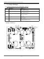
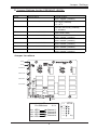
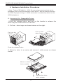
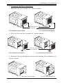
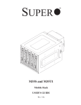
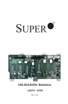
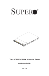
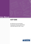
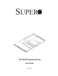
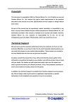
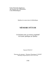
SUPER
®
CSE-M34S/CSE-M34T
Mobile Rack
USER'S GUIDE
Rev. 1.0
SUPER CSE-M34S/CSE-M34T User's Guide
Table of Contents
1. Packaging List .................................................................................................... 3
2. Technical Specifications ................................................................................... 3
3. Jumper Settings ................................................................................................. 4
4. Hardware Installation Procedures ................................................................ 6
5. SCSI(Super) GEM Drive Installation Instructions for Windows OS .......... 8
2
Packing List
CSE-M34S/CSE-M34T
Supermicro’s CSE-M34S/CSE-M34T Mobile Rack Series offers the cutting
edge technology with greater flexibility. The CSE-M34T supports four Serial
ATA hot-swappable hard drives that yield a unparalleled storage capacity
without compromising productivity by eliminating possible system downtime.
The CSE-M34S also accommodates four SCSI SCA 320/160 Hard drives
which provide configuration flexibility and maximum data integrity.
1. Packing List
Please check to see if you have received all the items listed below:
*CSE-M34S/CSE-M34T Mobile Rack
*90mm-Exhaust Fan
*Screws:
Six (6) counts of 6-32 hex washer head screws
Eight (8) counts of M3 washer head screws
Eighteen (18 )counts of Pan head screws
*Drive Carrier Four (4)CSE-PT10 (-beige only)
(*For CSE-M34T only)
*Serial ATA Backplane (CSESATA-M34)
*Four (4) Serial ATA Cables (CBL-0044)
*Serial ATA LED cable (CBL-0057)
(*For CSE-M34S only)
*SCSI Backplane (CSESCA-002)
*SCSI cable (CBL-027-U320)
2. Technical Specifications
Occupancy
Capacity
Cooling
Subsystem
System
Monitoring
Three (3) 5.25" Drive Bays
Four (4) 1" SCA Ultra320/160 Hard Drives with
SAF-TE built-in (*CSE-M34S only)
Four (4) 1" Host Receptacle Connectors, SATA
hot-swap hard drives (*CSE-M34Tonly)
One (1) 90mm Exhaust Fan
Fan Fail Detection LED and Alarm
Overheat LED indication
Built-in Termination (*CSE-M34S only)
Dimension
(WxHxD)
147mm x 129mm x 230mm
(5.8 in x 5.0 in x 9.1 in)
Weight
Gross: 6.8lb (3.4 kg)
Chassis supported:
SC762, SC830, SC942
3
SUPER CSE-M34S/CSE-M34T User's Guide
3. Jumper Settings
A. Jumper Settings for the CSE-M34S (SCSI):
Jumper
Description
Setting
JP14
Delay Start
Closed: Enable,
JP18
Buzzer Reset
Closed: Enable,
JP25
Overheat Temperature
Open: Disable (*Default)
Open: Disable (*Default)
Open: 50oC
1-2: 55oC (*Default)
2-3: 60oC
JP21
SCSI Termination
Closed: Enable (*Default),
JP24
SCSI ID Selection
1-2: SCSI IDs:0,1,2,3,4 (*Default)
Open: Disable
2-3: SCSI IDs:9,10,11,12,13
Jumper Locations
JP24
JP14 JP25
JP21
JP18
4
Jumper Settings
B. Jumper Settings for the CSE-M34T (SATA):
Jumper
Description
Setting
JP18
Buzzer Reset
JP25
Overheat Temperature
Closed: Enable,
Open: Disable (*Default)
Open: 45OC
1-2: 50OC (*Default)
2-3: 55OC
JP28
Fan Sense
JP26
Common Act#1-Act#4
JP27
Common Act In-Act#1
JP29
Common Act In-Act#2
JP30
Common Act In-Act#3
JP31
Common Act In-Act#4
JP32
Common Act Out
1-2: Enabled (if a fan is not present,
the alarm will sound) (*Default),
2-3: Disabled
Connect this header to CBL-0057
(SATA LED Cable)
Closed: Enable,
Open: Disable (*Default)
Closed: Enable,
Open: Disable (*Default)
Closed: Enable,
Open: Disable (*Default)
Closed: Enable,
Open: Disable (*Default)
Closed: Enable,
Open: Disable (*Default)
Jumper Locations
JP25
JP18
Channel #1
Channel #2
Channel #3
Channel #4
JP28
Activity LEDsPin Definitions
Act. LED 1
Act. LED 2
Act. LED 3
Act. LED 4
JP26
Channel 1
Channel 2
Channel 3
Channel 4
5
ACT1
JP26
ACT2
ACT3
ACT4
COM
Key
SUPER CSE-M34S/CSE-M34T User's Guide
4. Hardware Installation Procedures
(*Note: For the CSE-M34S: 1. SCSI IDs are assigned automatically by the
backplane. Do not set IDs manually on the drives. See the previous section
for SCSI ID jumper settings. 2. SCSI termination is enabled by default on the
SCSI backplane.)
A. Accessing Hot Swappable Drives:
1.Push the release button and pull up the handle to release the
drive tray as shown below on the left:
2. Pull out drive trays as shown below on the right:
Pull up the
drive trays
Pull up the
handle
Push the release button
3. Mount a drive in a carrier and secure it with screws as shown
below:
Mount a drive
into a carrier
Secure the drive
with screws
6
Installation Procedures
B. Accessing the Drive Backplane:
1. Remove the two screws as shown below:
Remove the
screws
The CSE-M34T (SATA) Model
The CSE-M34S(SCSI) Model
2. Pull out the rear fan bracket as shown below:
Pull out the rear
fan bracket
The CSE-M34S(SCSI) Model
The CSE-M34T(SATA) Model
3. Remove the six backplane screws and access the backplane as
shown below:
Remove the screws
7
Access the backplane
SUPER CSE-M34S/CSE-M34T User's Guide
5. SCSI (Super) GEM Driver Installation Instructions for
Windows OS
Please refer to the following instructions to install
Driver for the Windows OS systems.
the SCSI GEM
(*Note: This driver is not necessary for other Operating Systems. If you
have two SCA backplanes, you will need to install the driver twice.)
The driver is located on the Super Micro motherboard driver CD or is available
for download from our FTP site: ftp://ftp.supermicro.com/driver/Qlogic/
Follow the procedure below to install this driver to your system.
Installing the driver:
1) Right click on “My Computer” and choose “Property”.
2) Select “Hardware” tab and click on “Device Manager”.
3) Open “Other Devices” or wherever “GEM318” is on.
4) Right click on this device and choose “Property”.
5) Click on “Driver” tab and choose “Update Driver”.
6) Click “Next” 2 times, uncheck both “Floppy disk drives” and “CD-ROM
drives”. Then, select the item- “Specify a location,” and choose “Next”.
7) Click on “Browse” and choose D drive or wherever Supermicro Setup CD
is in.
8) Choose “Qlogic” folder and click on “Open”.
9) System will automatically detect GEM318 and install the drive from this
point on.
or,
1) Right click the "My Computer" icon on your desktop and choose Properties.
2) Click on the Hardware tab and click on "Device Manager" to bring up the
list of system devices.
3) You may see one or two yellow question marks (?) that read QLogic
GEM354 or GEM318 SCSI Processor Device. Right click on these, and
choose to uninstall. If two such question marks are present, uninstall both.
4) Click on Action tab and choose "Scan for Hardware Changes". The
Hardware Wizard program should start up. Click "Next".
5) At the first prompt, choose “Display a list of known device drivers for the
device so that I can choose a specific driver” and click "Next".
6) Choose “Other Devices” and click Next.
7) Choose “Have Disk”, and specify your floppy drive location in the options
box. Then, click "Next".
8) Highlight “Enclosure Services Device” and click "Next".
9) Ignore the warning prompt by clicking "Yes".
8