1
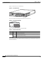
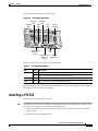
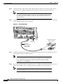
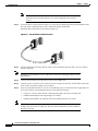
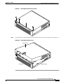
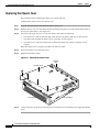
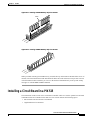
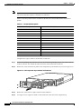
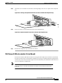
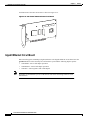
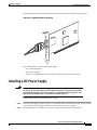
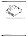
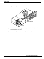
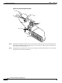
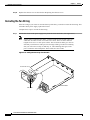
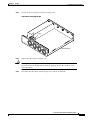
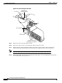
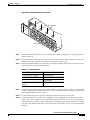
C H A P T E R
6
PIX 525
This chapter guides you through the installation of the PIX 525, and includes the following sections:
•
PIX 525 Product Overview
•
Installing a PIX 525
•
PIX 525 Feature Licenses
•
Installing Failover
•
Removing and Replacing a PIX 525 Chassis Cover
•
Replacing a Lithium Battery
•
Installing a Memory Upgrade
•
Installing a Circuit Board in a PIX 525
•
Installing a DC Power Supply
PIX 525 Product Overview
Figure 6-1 show the front view of the PIX 525.
PIX 525 Front Panel
61906
Figure 6-1
CISCO SECURITY PIX
525 SERIES
F I R E W A L L
POWER
ACTIVE
Cisco PIX Firewall Hardware Installation Guide
78-13880-01
6-1
Chapter 6
PIX 525
PIX 525 Product Overview
Figure 6-2 shows the rear view of the PIX 525.
PIX 525 Rear Panel
61907
Figure 6-2
F
A
I
L
O
V
E
R
100Mbps ACT
LINK
10/100 ETHERNET 1
100Mbps ACT
PIX-525
LINK
10/100 ETHERNET 0
USB
CONSOLE
There are two LEDs on the front panel of the PIX 525 (see Figure 6-3).
PIX 525 Front Panel LEDs
61913
Figure 6-3
Table 6-1 lists the state of the PIX 525 front panel LEDs.
Table 6-1
PIX 525 Front Panel LEDs
LED
Status
Description
POWER
On
On when the unit has power.
ACT
On
On when the unit is the active failover unit. If failover is present, the light is on
when the unit is the active unit.
Off
off when the unit is in standby mode.
There are three LEDs for the each RJ-45 interface port and three types of fixed interface connectors on
the back of the PIX 525.
Cisco PIX Firewall Hardware Installation Guide
6-2
78-13880-01
Chapter 6
PIX 525
Installing a PIX 525
Figure 6-4 shows the PIX 525 rear panel LEDs
Figure 6-4
PIX 525 Rear Panel LEDs
ACT(ivity)
ACT(ivity)
LED
LED
100Mbps
LINK
LINK
LED
LED
LED
Failover
connector
F
A
I
L
O
V
E
R
LINK
10/100 ETHERNET 1
100Mbps ACT
LINK
10/100 ETHERNET 0
PIX-525
USB
61912
100Mbps ACT
CONSOLE
10/100 BaseTX
USB
Ethernet 1
port
(RJ-45)
10/100 BaseTX
Console
Ethernet 0
port (RJ-45)
(RJ-45)
Table 6-2 lists the state of the PIX 525 rear panel LEDs.
Table 6-2
PIX 525 Rear Panel LEDs
LED
Status
Description
100 Mbps
On
Port 100 megabits per second 100BaseTX communication.
Off
Port is using 10 megabits per second data exchange.
ACT
On
Shows network activity.
LINK
On
Shows that data is passing through that interface.
The PIX 525 has RJ-45, network and console connectors, as well as a DB-15 failover cable connector.
The USB port is not used at the present time.
Installing a PIX 525
Complete these steps to install a PIX 525:
Step 1
The PIX 525 provides one set of brackets for installing the unit in an equipment rack. Complete these
steps if the unit is going to be installed into an equipment rack:
a.
Attach the brackets to the holes near the front of the unit on each side of the PIX 525 using the
supplied screws.
b.
Attach the unit to the equipment rack.
Cisco PIX Firewall Hardware Installation Guide
78-13880-01
6-3
Chapter 6
PIX 525
Installing a PIX 525
Step 2
Connect the cable so that you have either a DB-9 or DB-25 connector on one end as required by the
serial port for your computer, and the other end is the RJ-45 connector as shown in Figure 6-5.
Note
Step 3
Use the Console port to connect a computer to enter configuration commands.
Locate the serial cable from the accessory kit. The serial cable assembly consists
of a null modem cable with RJ-45 connectors, and one DB-9 connector and a
DB-25 connector.
Connect the RJ-45 serial cable connector to the PIX 525 console connector and connect the other end
to the serial port connector on your computer.
Figure 6-5
PIX 525 Rear Panel
F
A
I
L
O
V
E
R
LINK
100Mbps ACT
10/100 ETHERNET 1
LINK
10/100 ETHERNET 0
PIX-525
USB
CONSOLE
Console
port (RJ-45)
Computer serial port
DB-9 or DB-25
RJ-45 to
DB-9 or DB-25
serial cable
(null-modem)
Step 4
Connect the outside network cable to the remaining Ethernet port. Refer to “PIX 525 Feature Licenses”
for information on how to configure the ports.
Note
Step 5
61914
100Mbps ACT
The inside or outside network connections can be made to any available interface
port on the PIX 525. If you are only using the ETHERNET 0 and ETHERNET 1
ports, connect the inside network cable to the interface connector marked
ETHERNET 0 or ETHERNET 1.
If you need to install an optional circuit board, refer to “Installing a Circuit Board in a PIX 525”. If you
need to install memory, refer to “Installing a Memory Upgrade” for more information.
Note
It is not necessary to remove the chassis cover of the PIX 525 to access the circuit
boards or memory.
Cisco PIX Firewall Hardware Installation Guide
6-4
78-13880-01
Chapter 6
PIX 525
PIX 525 Feature Licenses
Step 6
Connect the network cables to the expansion interface ports. (The inside, outside, or perimeter network
connections can be made to any available interface port on the PIX 525.) The first expansion port
number, at the top left, is interface 2. Starting from that port and going from left to right and top to
bottom, the next port is interface 3, the next is interface 4, and so on. Refer to “PIX 525 Feature
Licenses” for information on how to configure the ports.
Step 7
If you have a second PIX Firewall to use as a failover unit, install the failover feature and cable as
described in “Installing Failover”.
Note
Step 8
Do not power on the standby failover unit until the primary unit has been configured.
When you are ready to start the PIX 525, power on the unit from the switch at the rear of the unit.
PIX 525 Feature Licenses
The VPN Accelerator Card (VAC) is integrated with PIX 525 unrestricted (UR) and failover (FO) bundles.
The VAC can also be purchased as a spare for use with PIX 525 units that have a restricted (R) license.
If you have a PIX-525-UR unrestricted feature license, the following options are available:
•
Note
Note
If you have a second PIX 525 to use as a failover unit, install the failover feature and cable as
described in “Installing Failover”.
Do not power on the failover units until the primary unit has been configured.
•
If needed, install the PIX Firewall Syslog Server as described on the logging command page in the
Cisco PIX Firewall Command Reference.
•
If you need to install an optional circuit board, refer to “Installing a Circuit Board in a PIX 525”.
•
If you need to install additional memory, refer to “Installing a Memory Upgrade”.
If, for any reason, you may choose to downgrade to any software version, note that you
need to use the clear flashfs command before doing so. A new section has been added to
Flash memory that must be cleared before downgrading.
For information on upgrading feature licenses or downloading the latest software versions, go to the
following website:
http://www.cisco.com/univercd/cc/td/doc/product/iaabu/pix/pix_sw/v_62/config/upgrade.htm
Installing Failover
Complete these steps to install a failover connection:
Step 1
Power off both the primary and secondary units.
Cisco PIX Firewall Hardware Installation Guide
78-13880-01
6-5
Chapter 6
PIX 525
Installing Failover
Note
Step 2
Both PIX Firewall units has to be the same model number, have at least as much
RAM, have the same Flash memory size, and be running the same software
version.
Locate the failover cable (shown in Figure 6-6). This cable is shipped separately from the PIX Firewall
unit. The cable is labeled Primary on one end and Secondary on the other.
Install the cable for the PIX 525 as shown in Figure 6-6.
Figure 6-6
PIX 525 Failover Cable Connection
F
A
I
L
O
V
E
R
PR
IM
AR
Y
Primary end
12395
F
A
I
L
O
V
E
R
DARY
SECON
Secondary end
Step 3
Note
Connect the Primary end of the failover cable to the first PIX Firewall unit, that is, the one you have
already configured.
We highly recommend that you use a GE failover link when connecting a PIX 525 with
GE interfaces.
Step 4
Connect the Secondary end of the failover cable to the standby unit.
Step 5
Connect a power cord to the power connector on the rear panel of each unit, and the other end of each
power cord to (preferably separate) power outlets.
Step 6
If you are using Stateful Failover, use one of the following types of connections, that is appropriate for
your system, between the dedicated interfaces on the PIX Firewall units:
Note
•
Category 5 crossover cable directly connecting the primary unit to the secondary unit.
•
100BaseTX half-duplex hub using straight Cat 5 cables.
•
100BaseTX full duplex on a dedicated switch or dedicated VLAN of a switch.
All enabled interfaces must be connected between the active and standby units. Only
configure the active unit. On a PIX 525, the active unit is indicated by the ACT LED on
the front of the unit.
Cisco PIX Firewall Hardware Installation Guide
6-6
78-13880-01
Chapter 6
PIX 525
Installing Failover
Caution
Do not turn the power on until the units are connected and the primary unit is configured
completely.
Cisco PIX Firewall Hardware Installation Guide
78-13880-01
6-7
Chapter 6
PIX 525
Removing and Replacing a PIX 525 Chassis Cover
Step 7
Power the primary unit on first, then power on the secondary unit. Within a few seconds, the active unit
automatically downloads its configuration to the standby unit.
If the primary unit fails, the secondary unit automatically becomes active.
Removing and Replacing a PIX 525 Chassis Cover
This section describes how to remove and replace the chassis cover from PIX 525. This section includes
the following topics:
•
Removing the Chassis Cover
•
Replacing the Chassis Cover
Removing the Chassis Cover
This section describes how to remove the PIX 525 chassis cover.
Note
Removing the PIX Firewall case does not affect your Cisco warranty. Upgrading the
PIX Firewall does not require any special tools and does not create any radio frequency
leak.
Complete these steps to remove the chassis cover:
Step 1
Power off the PIX 525 and disconnect site power.
Note
Note that the power switch is part of the power supply.
Step 2
Place the PIX 525 so that the front panel is facing you. If you place the PIX 525 on a table, ensure that
you have clear access to all sides.
Step 3
Remove the four screws on the chassis cover. (See Figure 6-7.)
Cisco PIX Firewall Hardware Installation Guide
6-8
78-13880-01
Chapter 6
PIX 525
Removing and Replacing a PIX 525 Chassis Cover
Figure 6-7
Removing the Chassis Cover Screws
PO
WER
TIVE
55324
AC
CIS
CO
SEC
U
F I RITY
R
PIX
E
W
52
A
L L 5 SERI
ES
Step 4
Lift the chassis cover upward and pull it away from the tabs on the rear of the chassis. (See Figure 6-8.)
Figure 6-8
Removing the Chassis Cover
Chassis cover
AC
55325
PO
WER
TIVE
CIS
CO
SEC
U
Front panel
F I RITY
R
PIX
E
W
52
A
L L 5 SERI
ES
Chassis bottom
Cisco PIX Firewall Hardware Installation Guide
78-13880-01
6-9
Chapter 6
PIX 525
Removing and Replacing a PIX 525 Chassis Cover
Replacing the Chassis Cover
This section describes replacing the chassis cover on the PIX 525.
Complete these steps to remove the chassis cover:
Step 1
Place the chassis bottom so that the front panel is facing you.
Step 2
Hold the chassis cover over the chassis bottom, and align each of the cover tabs with the chassis tabs at
the top rear of the chassis. (See Figure 6-9.)
Step 3
Lower the front of the top cover to close the chassis, and ensure the following:
•
The chassis cover tabs fit under the edge of the chassis rear panel so that they are not exposed.
•
The chassis tabs fit under the chassis cover so that they are not exposed.
•
The chassis cover side tabs on both sides fit inside the chassis side panels so that they are not
exposed.
When the chassis cover is properly assembled, no tabs are visible.
Step 4
Secure the chassis cover with four screws.
Step 5
Reinstall all interface cables.
Figure 6-9
Replacing the Chassis Cover
Chassis
tabs
Chassis cover
AC
55330
PO
WER
TIVE
CIS
CO
SEC
U
F I RITY
R
PIX
E
W
52
A
L L 5 SERI
ES
Front panel
Step 6
Chassis bottom
Connect the power to the site power and power on the PIX 525. The internal power supply fan should
go on.
Cisco PIX Firewall Hardware Installation Guide
6-10
78-13880-01
Chapter 6
PIX 525
Replacing a Lithium Battery
Replacing a Lithium Battery
The PIX Firewall has a lithium battery on its main circuit board. This battery has an operating life of
about 10 years. When the battery loses its charge, the PIX Firewall cannot function. Contact Cisco TAC
to replace the battery.
Note
Warning
Do not attempt to replace this battery yourself.
Danger of explosion exists if the lithium battery is incorrectly replaced. Replace only
with the same or equivalent type recommended by the manufacturer. Dispose of used
batteries according to the manufacturer's instructions.
Installing a Memory Upgrade
Observe the following warnings, cautions, and notes when installing additional PIX Firewall system
memory.
The following statement applies to DC models:
Warning
Before performing any of the following procedures, ensure that power is removed from
the DC circuit. To ensure that all power is OFF, locate the circuit breaker on the panel
board that services the DC circuit, switch the circuit breaker to the OFF position, and
tape the switch handle of the circuit breaker in the OFF position.
The following statement applies to both AC and DC models:
Warning
Before working on a system that has an On/Off switch, turn OFF the power and unplug
the power cord.
Caution
Always remove old memory before installing new memory.
Caution
If you remove a PIX Firewall chassis top panel, always reinstall the top panel. Running a
PIX Firewall without the top panel may cause overheating and damage to electrical
components.
Memory Installation Steps
Complete these steps to install additional system memory:
Step 1
If the unit is rack-mounted, remove network wires and any cords connecting to the PIX Firewall unit.
Ensure that the unit is unplugged from its power source.
Cisco PIX Firewall Hardware Installation Guide
78-13880-01
6-11
Chapter 6
PIX 525
Installing a Memory Upgrade
Step 2
Unpack the items in the memory upgrade kit.
Remove the component tray and all the screws holding the assembly in place. Refer to “Removing and
Replacing a PIX 525 Chassis Cover” for information on how to remove and replace the top panel.
Determine the location of your system memory sockets (see Figure 6-10).
Step 3
Use the markings on the motherboard to determine the socket numbers. Always install the first memory
board into the lowest socket number. Progressively add memory boards into higher numbered sockets.
61910
Figure 6-10 System Memory Location on the PIX 525 Component Tray
Step 4
Locate the wrist grounding strap in the accessory kit and connect one end to the unit or to the
PIX Firewall chassis, and securely attach the other to your wrist so it contacts your bare skin.
Step 5
With the wrist strap on your wrist, carefully grasp the memory strip from either end. Note that a DIMM
strip has notches.
Step 6
To install a DIMM strip:
•
Remove the old memory strip by opening the two plastic wing connectors, and pulling the old strip
up. Discard the old strip.
•
When installing the memory strip in a PIX 525, install the new strip in Bank 0 as shown in
Figure 6-11 and Figure 6-12, by opening the two plastic wing connectors, inserting the strip, and
closing the wing connectors.
Cisco PIX Firewall Hardware Installation Guide
6-12
78-13880-01
Chapter 6
PIX 525
Installing a Circuit Board in a PIX 525
Figure 6-11 Inserting a DIMM Memory Strip in a PIX 525
B
B
an
an k 2
B k
an 1
k
0
17997
DIMM
B
B
an
an k 2
B k
an 1
k
0
17998
Figure 6-12 Securing a DIMM Memory Strip in a PIX 525
When you finish inserting new RAM memory, reinstall the tray on the PIX 525. Reattach the screws. If
desired, rack mount the PIX Firewall and attach all cables and cords as discussed in previous sections.
After the PIX Firewall is installed, you can view the amount of RAM memory in the system startup
messages or with the show version command.
Installing a Circuit Board in a PIX 525
The information in this section refers to all PIX 525 models. Table 6-3 lists the optional circuit board
combinations that are available for the PIX 525. This section includes the following topics:
•
PIX Firewall VPN Accelerator Circuit Board
•
Gigabit Ethernet Circuit Board
Cisco PIX Firewall Hardware Installation Guide
78-13880-01
6-13
Chapter 6
PIX 525
Installing a Circuit Board in a PIX 525
Note
The PIX 525 Restricted Interface Options can have a maximum of 6 interfaces, and for the
Unrestricted Interface Options, a maximum of 8 interfaces.
Table 6-3 lists the possible choices available for the PIX 525 restricted and unrestricted interface
options.
Table 6-3
PIX 525 Interface Options
Restricted Interface Options
Unrestricted Interface Options
3 FE
3 FE
2 FE + 1 VPN Accelerator
2 FE + 1 VPN Accelerator
3 GE
3 GE
2 GE + 1 VPN Accelerator
2 GE + 1 VPN Accelerator
1 GE + 1 FE
1 GE + 2 FE
1 GE + 1 FE + 1 VPN Accelerator
1 GE + 1 FE + 1 VPN Accelerator
1 4-Port FE
1 4-port FE
1 4-Port FE + 1 VPN Accelerator
1 4-port FE + 2 FE
1 4-port FE + 2 GE
1 4-port FE + 1 VPN Accelerator
1 4-port FE + 1 VPN Accelerator + 1 FE
1 4-port FE + 1 VPN Accelerator + 1 GE
Complete these steps to install a circuit board in a PIX 525:
Step 1
Locate the grounding strap from the accessory kit. Fasten the grounding strap to your wrist so that it
contacts your bare skin. Attach the other end to bare metal on the PIX 525 chassis.
Step 2
Remove the screws from the rear panel of the component tray and slide the tray out (see Figure 6-13).
61908
Figure 6-13 The Component Tray at the Back of the PIX 525
F
A
I
L
O
V
E
R
100Mbps ACT
LINK
10/100 ETHERNET 1
100Mbps ACT
PIX-525
LINK
10/100 ETHERNET 0
USB
CONSOLE
Step 3
Remove the screw and cover plate from the circuit board slot.
Step 4
Use Figure 6-14 as a guide to install a circuit board into a PCI slot on the component tray.
Cisco PIX Firewall Hardware Installation Guide
6-14
78-13880-01
Chapter 6
PIX 525
Installing a Circuit Board in a PIX 525
Step 5
Attach the screw to hold the circuit board’s connecting flange to the rear cover plate on the component
tray.
61911
Figure 6-14 Inserting an Expansion Board into a PCI Slot on the PIX 525 Component Tray
Step 6
Figure 6-15 shows circuit boards in PCI slots on the component tray.
61909
Figure 6-15 Expansion Boards in PCI Slots on the PIX 525 Component Tray
Step 7
Reinstall the component tray into the PIX 525 chassis.
PIX Firewall VPN Accelerator Circuit Board
The VPN Accelerator (PIX-VPN-ACCEL) is an encryption and compression accelerator circuit board.
The VPN Accelerator uses a PCI interface and therefore can only be installed in PIX Firewall platforms
with PCI slots. The VPN Accelerator begins to function immediately after installation without the need
of special installation configurations.
Note
The new VPN Accelerator cannot be used with the former PIX Firewall IPSec accelerator
in the same chassis. The PIX Firewall IPSec accelerator was also known as the Private
Link card.
Cisco PIX Firewall Hardware Installation Guide
78-13880-01
6-15
Chapter 6
PIX 525
Installing a Circuit Board in a PIX 525
An illustration of the VPN Accelerator is shown in Figure 6-16.
61921
Figure 6-16 PIX Firewall VPN Accelerator Circuit Board
Gigabit Ethernet Circuit Board
PIX Firewall supports 1000 Mbps (Gigabit) Ethernet. The Gigabit Ethernet circuit board uses the
gb-ethernet device name and only has one hardware speed and the following duplex options:
Note
•
1000SXfull—Forces full-duplex operation
•
1000BaseSX—Forces half-duplex operation
•
1000auto—Auto negotiates full or half duplex
We highly recommend that you use a GE failover link when connecting a PIX 525 with
GE interfaces.
Cisco PIX Firewall Hardware Installation Guide
6-16
78-13880-01
Chapter 6
PIX 525
Installing a DC Power Supply
The Gigabit Ethernet circuit board and the fiber optic cable connection are shown in Figure 6-17.
33010
Figure 6-17 Gigabit Ethernet Circuit Board
TX
RX
LINK
The Gigabit Ethernet circuit board has three LEDs:
•
TX—Transmitting data
•
RX—Receiving data
•
LINK—The Gigabit Ethernet circuit board has established a network connection
Installing a DC Power Supply
Warning
Before performing any of the following procedures, ensure that power is removed from
the DC circuit. To ensure that all power is OFF, locate the circuit breaker on the panel
board that services the DC circuit, switch the circuit breaker to the OFF position, and
tape the switch handle of the circuit breaker in the OFF position.
Complete these steps to install the DC power supply:
Step 1
Place the power supply as shown in Figure 6-18, and then slide it toward the rear panel. You will be able
to feel the chassis hook engage with the slot on the bottom of the power supply.
Step 2
Reinstall the three screws that secure the power supply on the back panel of the chassis.
Cisco PIX Firewall Hardware Installation Guide
78-13880-01
6-17
Chapter 6
PIX 525
Installing a DC Power Supply
Figure 6-18 Inserting the Power Supply in the Chassis
Power
supply
55329
Chassis hook
Power
supply
slot
Chassis bottom
Step 3
Connect the six-pin connector to the motherboard.
Step 4
Route the fan cables on top of fans exactly as shown in Figure 6-19. Note that the two longest cables
are connected to the two installed fans on the right. The connectors to these two fans will fit into the
space between the second and third fans.
Step 5
Reconnect the power connector.
Cisco PIX Firewall Hardware Installation Guide
6-18
78-13880-01
Chapter 6
PIX 525
Installing a DC Power Supply
31109
Figure 6-19 Routing the Fan Cables
Sheet metal tabs
Base tabs
Front panel
Step 6
Insert the second fan as shown in Figure 6-19, making sure that the fan cable feeds to your left. Position
the cables to the two installed fans so that they will fit over the first and second fans. Press the fan into
place between the four sheet metal tabs.
Step 7
Reconnect the two-pin fan cables to the remaining fan, as shown in Figure 6-20.
Cisco PIX Firewall Hardware Installation Guide
78-13880-01
6-19
Chapter 6
PIX 525
Installing a DC Power Supply
Figure 6-20 Reconnecting the Fan Cables
Fan
Fan connector
31910
Front panel
Step 8
Reinstall the remaining fan. Make sure you orient the fan so that the cables feed to the right (toward
the second fan). Route the cable over the fan before you reconnect it. When correctly assembled, the
cables appear as shown in Figure 6-21.
Step 9
Starting with the fan farthest away from the power supply, bend the cable clamps over wires and into
the gap between chassis and fan housing.
Cisco PIX Firewall Hardware Installation Guide
6-20
78-13880-01
Chapter 6
PIX 525
Installing a DC Power Supply
31109
Figure 6-21 Correct Fan Cable Routing
Sheet metal tabs
Base tabs
Front panel
Step 10
Replace the air separator as shown in Figure 6-22, holding all cables to the right of the separator as
you slip it into the chassis.
Figure 6-22 Replacing the Air Separator
Air separator
52021
Front panel
Cisco PIX Firewall Hardware Installation Guide
78-13880-01
6-21
Chapter 6
PIX 525
Installing a DC Power Supply
Step 11
Replace the chassis cover as described in “Replacing the Chassis Cover.”
Rerouting the Fan Wiring
If the fan wiring in your router is not routed on top of the fans, you need to reroute the fan wiring. This
will make future power supply replacement easier.
Complete these steps to reroute the fan wiring:
Step 1
Pull the fan closest to the power supply away from the sheet metal tabs. (See Figure 6-23.)
Note
To help with reconnecting the cables, write down which colored cable connects to
which fan. See Table 6-4 for a list of the wire colors. There are three different
lengths of two-wire 12 VDC power cables. The two shortest cables go to the two
fans that you will remove in Step 9. The two longer cables go to the two remaining
fans you will remove in Step 10 and Step 11. The remaining cable goes to the
power connector on the backplane. These cables are color-coded.
Figure 6-23 Pulling the Fan Away from the Tabs
55326
Fan
Chassis bottom
Fan tabs
Cisco PIX Firewall Hardware Installation Guide
6-22
78-13880-01
Chapter 6
PIX 525
Installing a DC Power Supply
Step 2
Lift the fan out of the chassis as shown in Figure 6-24.
Figure 6-24 Removing the Fan
55327
Fan
Chassis bottom
Step 3
Caution
Step 4
Depress the tab as shown in Figure 6-25.
Do not attempt to remove the fan cables without first depressing the tab as shown in
Figure 6-25. You can damage the fan cables by applying stress if the connector is not
removed properly.
Disconnect the fan cable as shown in Figure 6-25, and set the fan aside.
Cisco PIX Firewall Hardware Installation Guide
78-13880-01
6-23
Chapter 6
PIX 525
Installing a DC Power Supply
Figure 6-25 Disconnecting the Fan Cable
Depress tab
and pull outward
Fan
Fan connector
31106
Power supply
Location of the three
remaining fan connectors
Step 5
Remove the next fan and disconnect its cable.
Step 6
Remove the cables for the two remaining fans. Remove the last two fans.
Step 7
Replace the fans, starting with the fan farthest away from the power supply. If the bezel has been
removed, make sure the fan farthest away from the power supply does not cover the bezel holes.
Note
Step 8
Make sure that the label on the fan faces the chassis wall to ensure proper airflow direction.
Install cable clamps onto the fans by aligning cable clamp holes over fan mounting holes and pressing
rivets through both. (See Figure 6-26.)
Cisco PIX Firewall Hardware Installation Guide
6-24
78-13880-01
Chapter 6
PIX 525
Installing a DC Power Supply
Figure 6-26 Inserting Cable Clamp to the Fan
Wiring clamp
31335
Front panel
Step 9
Reconnect the two-pin fan cables to the remaining fan, as shown in Figure 6-26. Fan wiring colors are
listed in Table 6-4.
Step 10
Route the fan wire on the top surface of the fans. Place the fan wires straight, and do not twist the wires
together. Locate the connectors in the gap between fans. (See Figure 6-21.)
Step 11
Starting with the fan farthest away from the power supply, bend the cable clamps over the wires and
into the gap between chassis and fan housing.
Table 6-4
Fan Wiring Colors
Fan Number
Wire colors
1 (closest to power supply)
Purple and black
2
Green and black
3
Blue and black
4 (farthest away from power
supply)
Brown and black
Step 12
Terminate the DC input wiring on a DC source capable of supplying at least 15 amps. A 15-amp circuit
breaker is required at the 48 VDC facility power source. An easily accessible disconnect device should
be incorporated into the facility wiring.
Step 13
Be sure the PIX 525 power is off by checking the power switch at the rear of the unit.
Step 14
As shown in Figure 6-27, the PIX 525 is equipped with two grounding studs at the back of the unit,
which you can use to connect a two-hole grounding lug to the PIX 525. Use the 10-32 nuts provided
with the PIX 525 to connect a copper standard barrel grounding lug to the studs. The PIX 525 requires
a lug where the distance between the center of each hole is 0.56 inches. A lug is not supplied with the
PIX 525.
Cisco PIX Firewall Hardware Installation Guide
78-13880-01
6-25
Chapter 6
PIX 525
Installing a DC Power Supply
Figure 6-27 Attaching a Grounding Lug to the PIX Firewall
Rear of
PIX Firewall
11827
– +
To rack
ground
10-32 nuts
Grounding studs on
PIX Firewall DC model
2-hole copper
standard barrel
grounding lug
Step 15
Ensure that power is removed from the DC circuit. To ensure that all power is OFF, locate the circuit
breaker on the panel board that services the DC circuit, switch the circuit breaker to the OFF position,
and tape the switch handle of the circuit breaker in the OFF position.
Step 16
Strip the ends of the wires for insertion into the power connect lugs on the PIX 525.
Step 17
Refer to Figure 6-28 and insert the ground wire into the connector for the earth ground and tighten the
screw on the connector. Using the same method as for the ground wire, connect the negative wire and
then the positive wire.
Figure 6-28 Attaching DC Power Cables
11779
– +
Cisco PIX Firewall Hardware Installation Guide
6-26
78-13880-01
Chapter 6
PIX 525
Installing a DC Power Supply
Step 18
Reconnect power to the PIX 525. After wiring the DC power supply, remove the tape from the circuit
breaker switch handle and reinstate power by moving the handle of the circuit breaker to the ON
position.
Step 19
Insert the PIX 525 system diskette in the drive at the front of the unit.
Step 20
Power on the unit from the switch at the rear of the unit.
If you need to power cycle the DC PIX Firewall, wait at least 5 seconds between powering off the unit
and powering it back on.
Cisco PIX Firewall Hardware Installation Guide
78-13880-01
6-27
Chapter 6
PIX 525
Installing a DC Power Supply
Cisco PIX Firewall Hardware Installation Guide
6-28
78-13880-01