1
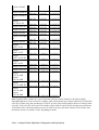
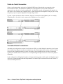
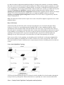
Cisco − Catalyst Switch GigaStack Configuration and Implications
Table of Contents
Catalyst Switch GigaStack Configuration and Implications..........................................................................1
Document ID: 22360................................................................................................................................1
Introduction..........................................................................................................................................................1
Prerequisites.........................................................................................................................................................1
Requirements..........................................................................................................................................1
Components Used...................................................................................................................................3
Conventions............................................................................................................................................3
Cabling Configuration.........................................................................................................................................3
Point−to−Point Connection.....................................................................................................................4
Cascaded Stack Connections..................................................................................................................4
Cascaded Stack Connections with a Redundant Link.............................................................................5
Using the Cross−Tack Uplink Fast Feature............................................................................................5
Troubleshooting...................................................................................................................................................8
NetPro Discussion Forums − Featured Conversations......................................................................................10
Related Information...........................................................................................................................................10
i
Catalyst Switch GigaStack Configuration and
Implications
Document ID: 22360
Introduction
Prerequisites
Requirements
Components Used
Conventions
Cabling Configuration
Point−to−Point Connection
Cascaded Stack Connections
Cascaded Stack Connections with a Redundant Link
Using the Cross−Tack Uplink Fast Feature
Troubleshooting
NetPro Discussion Forums − Featured Conversations
Related Information
Introduction
The GigaStack Gigabit Interface Converter (GBIC) is a Cisco proprietary GBIC. The GigaStack GBIC
provides low cost, high bandwidth connections between supported devices. Gigabit connections can be
configured in a point−to−point or cascaded stack configuration, with or without redundancy.
The GigaStack GBIC allows you to stack up to nine switches to form an independent backbone that can be
managed with a single IP address. This stack gives the appearance of a single large switch for network
management purposes. You can also form a point−to−point link between two switches. The GigaStack GBIC
supports one full−duplex link (in a point−to−point link), or up to eight half−duplex links (in a stack
configuration) to other Gigabit Ethernet devices.
This document outlines the necessary steps to insure a working configuration and possible issues related to a
misconfiguration.
Prerequisites
Requirements
The following table shows the list of Cisco switches that support the GigaStack GBIC, along with the IOS that
supports redundant loop configuration. Redundant loop configuration is not supported in any prior release.
The GigaStack GBIC is not supported in the Catalyst 4000, Catalyst 5000, and Catalyst 6000 product line.
Model
Minimum
Release
Minimum
Required to
Release
Minimum
support
Required for Recommend
GigaStack
Loop
Release
11.2(8)SA6 12.0(5)XU
12.0(5)WC3b
Detection
Cisco − Catalyst Switch GigaStack Configuration and Implications
Catalyst 2912MF
XL
Catalyst 2924M XL
Catalyst 2924M XL
DC
Catalyst
WS−X2931−XL
Catalyst 3508G XL
Catalyst 3512 XL
Catalyst 3524 XL
Catalyst 3524 PWR
XL
Catalyst 3548 XL
Catalyst
2950G−12−EI
Catalyst
2950G−24−EI
Catalyst
2950G−24−EI−DC
Catalyst
2950G−48−EI
Catalyst 3550−12G
Catalyst 3550−12T
Catalyst
3550−24−SMI
Catalyst
3550−24−EMI
Catalyst
3550−24−SMI−DC
Catalyst
3550−48−SMI
Catalyst
3550−48−EMI
11.2(8)SA6
12.0(5)XU
12.0(5)WC3b
12.0(5)XU
12.0(5)XU
12.0(5)WC3b
11.2(8)SA6
12.0(5)XU
12.0(5)WC3b
11.2(8)SA6
12.0(5)XU
12.0(5)WC3b
11.2(8)SA6
12.0(5)XU
12.0(5)WC3b
11.2(8)SA6
12.0(5)XU
12.0(5)WC3b
12.0(5)XU
12.0(5)XU
12.0(5)WC3b
12.0(5)XP
12.0(5)XU
12.0(5)WC3b
12.1(6)EA2
12.1(6)EA2
12.1(6)EA2c
12.1(6)EA2
12.1(6)EA2
12.1(6)EA2c
12.1(6)EA2
12.1(6)EA2
12.1(6)EA2c
12.1(6)EA2
12.1(6)EA2
12.1(6)EA2c
12.1(6)EA1
12.1(6)EA1
12.1(8)EA1c
12.1(4)EA1c 12.1(4)EA1c 12.1(8)EA1c
12.1(6)EA1a 12.1(6)EA1a 12.1(8)EA1c
12.1(6)EA1b 12.1(6)EA1b 12.1(8)EA1c
12.1(8)EA1b 12.1(8)EA1b 12.1(8)EA1c
Note: Upgrade all the switches in a series to the same software version. Otherwise, the loop−breaking
algorithm might never resolve itself. For example, if the stack includes only Catalyst 2900 series XL and 3500
series XL switches, they must run Release 12.0(5)XU or later. If the stack includes a mixture of Catalyst 2900
series XL, 3500 series XL, 2950, and 3550 switches, all the 2900 XL and 3500 XL switches must run Release
12.0(5)XW or later, all 2950 switches must run 12.1(6)EA2 or later, and all the Catalyst 3550 switches must
run Release at least 12.1(4)EA1 or later, depending on model.
Cisco − Catalyst Switch GigaStack Configuration and Implications
Components Used
The GigaStack GBIC is an adapter that can only be installed into the GBIC modules slot of any supported
switch. The maximum distance for a GBIC−to−GBIC connection is one meter. The GigaStack GBIC requires
Cisco proprietary signaling and cabling. Each GigaStack GBIC consists of two ports, port 1 and port 2. One or
both ports can be used, depending on cabling configuration.
• GBIC: WS−X3500−XL (Cisco GigaStack GBIC and 50 centimeter cable for GigaStack GBIC)
• Cable: CAB−GS−1M (one meter cable/39.3696 inches)
• Cable: CAB−GS−50CM (50 centimeter cable/19.6850 inches)
Caution: Do not use standard IEEE 1394 cables with the GigaStack GBIC. You must use one of the
Cisco proprietary cables (CAB−GS−50CM or CAB−GS−1M). If you use any other cable, you will not have
connectivity.
Caution: Do not use the GigaStack GBIC with standard IEEE 1394 equipment. You might damage the
equipment or lose data.
Conventions
For more information on document conventions, refer to the Cisco Technical Tips Conventions.
Cabling Configuration
It is extremely important to understand how to physically connect the GigaStack GBICs and what mode of
operation will occur. Each physical configuration is is cabled somewhat differently and may require the use of
more than one GigaStack per switch. Failure to comply may result in a loss of connectivity. The GigaStack
GBIC can be cabled in one of the following three ways:
• Point−to−point
• Cascaded stack
• Cascaded stack with a redundant link
The GigaStack GBIC will auto negotiate to either full−duplex or half−duplex. The software determines the
mode of operation by the way the cables are connected and the number of switches in the stack.
Note that although duplex can be forced, it is not supported. The only supported option for duplex is to leave
it to auto−negotiate.
Cisco − Catalyst Switch GigaStack Configuration and Implications
Point−to−Point Connection
Point−to−point connections consist of one GigaStack GBIC per switch and only one connection exists
between these modules. The additional available port on the Gigastack is not used and should not be
connected to any other device. In this configuration, the GigaStack interface will automatically negotiate to
full−duplex. One switch can have multiple point−to−point connections with neighbors as long as you are only
using one per port on separate GigaStacks to neighboring switches.
In point−to−point operations, it does not matter what port is connected to the neighbor's port. For example,
GigaStack port 1 on switch A can be connected to GigaStack port 2 on switch B.
Cascaded Stack Connections
Cascaded stack configurations consist of one GigaStack GBIC per switch. Multiple connections exist between
these modules. By using one module per switch, you are able to interconnect between three and nine switches
using only one GigaStack module per switch. The cable is daisy chained between switches by connecting
opposite port numbers between switches. Port 1 to neighboring switch port 2 and so on. There is no physical
redundancy.
In this configuration, all GigaStack interfaces will automatically negotiate to half−duplex. All GigaStack ports
will act as a repeater and share the one Gbps channel. The shared Gigabit connection between all switches is
called a multidrop backbone.
Cisco − Catalyst Switch GigaStack Configuration and Implications
Caution: GBICs are sensitive to power spikes. It is advised to regulate the power to the devices to
avoid GBIC failures.
Cascaded Stack Connections with a Redundant Link
Cascaded stack configuration with a redundant link consists of one GigaStack GBIC per switch. Multiple
connections exist between these modules. By using one module per switch, you are able to interconnect
between three and nine switches using only one GigaStack module per switch. The cable is daisy chained
between switches by connecting opposite port numbers between switches. Port 1 to neighboring switch port 2
and so on. Physical redundancy occurs when you complete the connection between the first and last switch.
Every port in all GigaStack modules will have a connection in use.
In this configuration, all GigaStack interfaces will automatically negotiate to half−duplex. All GigaStack ports
will act as a repeater and share the one Gbps channel. A loop configuration will be detected by a loop
detection algorithm and one of the links on a GigaStack module will be used as the redundant link. The
redundant link in the stack is disabled for data transmission while all other links in the stack are up. When
another link in the stack goes down, the redundant link will be enabled for data transmission. No user
intervention is required.
Note: This configuration is only supported if all switches in the stack run software that supports the loop
detection mechanism.
Using the Cross−Tack Uplink Fast Feature
Cross−stack UplinkFast (CSUF) provides a fast spanning−tree transition (fast convergence in less than one
second under normal network conditions) across a stack of switches that use the GigaStack GBICs connected
Cisco − Catalyst Switch GigaStack Configuration and Implications
in a shared cascaded configuration (multidrop backbone). During the fast transition, an alternate redundant
link on the stack of switches is placed in the forwarding state without causing temporary spanning−tree loops
or loss of connectivity to the backbone. With this feature, you can have a redundant and resilient network in
some configurations. On the catalyst 2900/3500XL, 2950, and 3550 series switches you enable CSUF by first
entering the spanning−tree uplinkfast command in global configuration mode, and then using the
spanning−tree stack−port interface configuration command on the Gigastack interface desired. On catalyst
switches 3750 CSUF is automatically enabled when you enable the UplinkFast feature by using the
spanning−tree uplinkfast global configuration command. The CSUF feature is supported only when the
switch is running PVST.
Note: The 2900xl and 3500xl switches require code version 12.0(5)XW or higher to support the Cross−stack
uplinkfast feature.
How CSUF Works
CSUF ensures that one link in the stack is elected as the path to the root. As shown in the figure below,
Switches A, B, and C are cascaded through the GigaStack GBIC to form a multidrop backbone, which
communicates control and data traffic across the switches at the access layer. The switches in the stack use
their stack ports to communicate with each other and to connect to the stack backbone; stack ports are always
in the spanning−tree forwarding state. The stack−root port on Switch A provides the path to the root of the
spanning tree; the alternate stack−root ports on Switches B and C can provide an alternate path to the
spanning−tree root if the current stack−root switch fails or if its link to the spanning−tree root fails.
Link A, the root link, is in the spanning−tree forwarding state; Links B and C are alternate redundant links
that are in the spanning−tree blocking state. If Link A, Switch A or its stack−root port fails, CSUF selects
either the Switch B or Switch C alternate stack−root port and puts it into the forwarding state in less than one
second.
Cross−Stack UplinkFast Topology
CSUF uses the Stack Membership Discovery Protocol to build a neighbor list of stack members through the
receipt of discovery hello packets. When certain link loss or spanning−tree events occur (described in the
Cisco − Catalyst Switch GigaStack Configuration and Implications
Events that Cause Fast Convergence section of this document), the Fast Uplink Transition Protocol uses the
neighbor list to send fast−transition requests on the stack port to stack members.
The switch sending the fast−transition request needs to do a fast transition to the forwarding state of a port
that it has chosen as the root port, and it must obtain an acknowledgement from each stack switch before
performing the fast transition.
Each switch in the stack determines if the sending switch is a better choice than itself to be the stack root of
this spanning−tree instance by comparing the root, cost, and bridge ID. If the sending switch is the best choice
as the stack root, each switch in the stack returns an acknowledgement; otherwise, it does not respond to the
sending switch (drops the packet). The sending switch then has not received acknowledgements from all stack
switches.
When acknowledgements are received from all stack switches, the Fast Uplink Transition Protocol on the
sending switch immediately transitions its alternate stack−root port to the forwarding state. If
acknowledgements from all stack switches are not obtained by the sending switch, the normal spanning−tree
transitions (blocking, listening, learning, and forwarding) take place, and the spanning−tree topology
converges at its normal rate (2 * forward−delay time + max−age time).
The Fast Uplink Transition Protocol is implemented on a per−VLAN basis and affects only one spanning−tree
instance at a time.
Events that Cause Fast Convergence
Depending on the network event or failure, the CSUF fast convergence may or may not occur. Fast
convergence (less than one second under normal network conditions) occurs under these circumstances:
• The stack−root port link fails.
If two switches in the stack have alternate paths to the root, only one of the switches performs the fast
transition.
• The failed link, which connects the stack root to the spanning−tree root, recovers.
• A network reconfiguration causes a new stack−root switch to be selected.
• A network reconfiguration causes a new port on the current stack−root switch to be chosen as the
stack−root port.
Note: The fast transition might not occur if multiple events occur simultaneously. For example, if a stack
member switch is powered off while the link connecting the stack root to the spanning−tree root comes back
up, the normal spanning−tree convergence occurs.
Normal spanning−tree convergence (30 to 40 seconds) occurs under the following conditions:
• The stack−root switch is powered off, or the software failed.
• The stack−root switch, which was powered off or failed, is powered on.
• A new switch, which might become the stack root, is added to the stack.
• A switch other than the stack root is powered off or failed.
• A link fails between stack ports on the multidrop backbone.
Limitations
These limitations apply to CSUF:
Cisco − Catalyst Switch GigaStack Configuration and Implications
• CSUF uses the GigaStack GBIC and runs on all Catalyst 3550 switches, all Catalyst 3500 XL
switches, Catalyst 2950 switches with GBIC module slots, and only on modular Catalyst 2900 XL
switches that have the 1000BASE−X module installed.
• Up to nine stack switches can be connected through their stack ports to the multidrop backbone. Only
one stack port per switch is supported.
• Each stack switch can be connected to the spanning−tree backbone through one uplink.
• If the stack consists of a mixture of Catalyst 3550, Catalyst 3500 XL, Catalyst 2950, and Catalyst
2900 XL switches, up to 64 VLANs with spanning tree enabled are supported. If the stack consists of
only Catalyst 3550 switches, up to 128 VLANs with spanning tree enabled are supported.
• The CSUF feature is supported only when the switch is running PVST .
• If a stack that has Catalyst 2955, Catalyst 2950, or Catalyst 2940 switches also has Catalyst 2900 XL
or Catalyst 3500 XL switches, cross−stack UplinkFast (CSUF) does not function if the management
VLAN on the Catalyst 2900 XL or Catalyst 3500 XL switches is changed to a VLAN other than
VLAN 1 (the default). The workaround is to make sure that the management VLANs of all Catalyst
2900 XL or 3500 XL switches in the stack are set to VLAN 1. (CSCdv82224)
Troubleshooting
The following are troubleshooting steps to take on a case by case scenario:
• For common problems and their solutions, refer to the following document:
Common Problems and Their Solutions
• For an explanation of GigaStack LEDS, refer to the following document:
GigaStack GBIC LEDs
Error Message: NO_LOOP_DETECT
NO_LOOP_DETECT, GIGASTACK, LOG_ALERT, 0, The link neighbor of link %d of GigaStack
This error message indicates that there is no acknowledgment for GigaStack loop detection request received
from one of the links on a GigaStack GBIC. Either the neighboring switch does not support the GigaStack
loop breaking algorithm, or the link between the two GigaStack GBICs is broken. Under this condition, a
GigaStack loop topology is not be automatically detected, and the connectivity between switches in the stack
could be lost.
If loop topology is used in the GigaStack, make sure the latest software is running on all switches in the stack.
Check the GigaStack GBICs involved to make sure they are functioning.
If no loop exists in the GigaStack GBIC stack, as a workaround, you can disable the loop−breaking algorithm
by issuing the no gigastack loop−breaking [interface−id] global configuration command. This is meant as a
workaround until you can upgrade all switches to support loop breaking.
One Way Traffic Flow
When using the GigaStack GBIC with a Catalyst 3500 XL switch or 2900 XL modular switch and IOS
Release 11.2(8.1)SA6, you may experience a problem with traffic flow in one direction when you insert or
remove a cable. This is resolved in 11.2(8.2) SA6 and greater.
Link Flaps and Never Stabilizes
Cisco − Catalyst Switch GigaStack Configuration and Implications
When two switches are connected by a GigaStack GBIC and duplex is forced to full on both ends, the link
may flap and never stabilize. When reconfigured to auto duplex on both ends, the link still will not stabilize.
After reinserting one of the razors, the link finally stabilizes. This is also seen when link negotiation is shut
off. Duplex must always be auto−negotiated when a GigaStack GBIC is inserted.
Configure the GigaStack ports to auto−negotiate duplex by issuing the interface command duplex auto.
Configure the GigaStack port to negotiate the link by issuing the interface command negotiation auto. Once
complete, remove and reinsert the GigaStack GBIC.
The show interface command will show the negotiated state for the GigaStack. Check for the following
values in the show interface command output:
Auto−duplex (Half), 1000Mb/s, media type is CX_GIGASTACK
Note: Link and duplex auto negotiation are the default configuration for the GigaStack interfaces.
Message: %GIGASTACK−6−LOOP_DETECTED
In a redundant loop configuration, an election of which GigaStack link is to be blocked occurs, also known as
master loop breaker. All the LEDs on all GigaStacks will flash amber. Once the master loop breaker has been
elected, all GigaStack LEDs will be solid green with the exception of the blocked master loop breaker. This
link will be solid amber.
The following message is displayed on the elected master loop breaker switch:
%GIGASTACK−6−LOOP_DETECTED: Gigastack GBIC in
is selected as Master Loop Breaker.
Link 2 of the master loop breaker GigaStack GBIC is disabled to break the loop. Issuing the show interface
command on the master loop breaker port will display the following:
GigaStack module(0.1) in GBIC slot. link1 is up, link2 is redundant link.
This is normal operation and the message is for informational purposes only. During this time, you may see
the links go up/down multiple times. This is normal behavior. ]
The loop breaking algorithm occurs between the GigaStack GBICs by exchanging MAC addresses using their
A− and B−ports. The winner of the election, the one with the lowest byte−order reversed MAC address, will
become the master loop breaker and disable its port 2. For example, if a gig port has the MAC address
00:d0:79:6b:ee:01 (00d0.796b.ee01), the byte−order reversed MAC address is ee:01:79:6b:00:d0
(ee01.796b.00d0).
To determine the Master Loop Breaker, the reversed MAC addresses are broken into seven data bit chunks,
with the first chunk having the highest significance as Master Loop Breaker. The loop breaker will be the
seven data bit chunk with the lowest value. If the first seven data bit chunks are identical, then compare the
next seven bits until there is a loop breaker.
To find out which switch will disable its B−port, issue the sh int gig x/y command on each switch and make
note of the MAC address in parentheses (the one that says bia and then a MAC address). With this
information, perform the byte−order reversing operation and then compare the first seven data bit chunks to
find the lowest value. The reversed MAC address with the lowest value in its first seven data bit chunk will be
the master loop breaker and will disable its port 2. If the first seven data bit chunks are identical, compare the
next group until a non−identical comparison value can be found.
Cisco − Catalyst Switch GigaStack Configuration and Implications
NetPro Discussion Forums − Featured Conversations
Networking Professionals Connection is a forum for networking professionals to share questions, suggestions,
and information about networking solutions, products, and technologies. The featured links are some of the
most recent conversations available in this technology.
NetPro Discussion Forums − Featured Conversations for LAN
Network Infrastructure: LAN Routing and Switching
Network Infrastructure: Getting Started with LANs
Related Information
• GigaStack Gigabit Interface Converter (GBIC)
• Technical Support − Cisco Systems
All contents are Copyright © 1992−2005 Cisco Systems, Inc. All rights reserved. Important Notices and Privacy Statement.
Updated: Sep 01, 2005
Cisco − Catalyst Switch GigaStack Configuration and Implications
Document ID: 22360