1
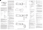
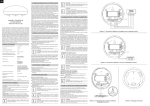
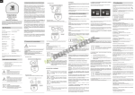
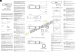
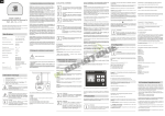
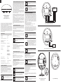
ENG
Battery Type:
CR123A
Power Consumption (at VDC operation):
0,4W
Output terminals maximum current
carrying capacity
(ALARM NC, TAMP NC):
25mA
Maximum voltage at output terminals:
24V DC / 20V AC
1) Make sure a DC power source is disconnected and the sensor is located within
direct communication with the main controller’s range. The battery must be
removed.
2) Open the cover.
3) Set the main controller into the learning mode (see a main controller’s operating
manual).
4) Connect a DC power source to include the Fibaro Flood Sensor into the Z-Wave
network in autoinclusion mode.
5) Fibaro Flood Sensor will be detected and included.
i
NOTE
In case the Sensor is not detected, proceed to the manual
inclusion (described below) or reset the Sensor and repeat auto
inclusion procedure.
To deactivate auto inclusion mode, press TMP button once, after the Fibaro Flood
Sensor has been connected to a DC power supply.
Manual Z-Wave network inclusion:
EU standards compliance:
EMC 2004/108/EC
R&TTE 1999/5/WE
Radio protocol:
Z - Wave
Radio frequency:
868,4 MHz EU;
908,4 MHz US;
921,4 MHz ANZ;
869,2 MHz RU;
Range:
up to 50m outdoors
up to 30m indoors
(Depending on terrain
and building structure)
Operational Temperature:
0 - 40oC*
Measured temperature range:
-20 to 100oC
Temperature measuring accuracy:
0,5oC (within 0 - 40oC range)
Dimensions (Diameter x Height):
72 x 28 mm
* Operational temperature in VDC powering mode: -20oC - 70oC
TECHNICAL INFORMATION
• Compatible with any Z-Wave network controller,
• May be connected to any alarm system (potential free output terminal),
• Extremely easy installation - simply put on a surface prone to flooding,
• May be installed anywhere - flood sensor’s contacts extended with a wire,
• Battery or VDC powered. When connected to an external, VDC power source, the
battery serves as an emergency power source,
• Theft protection - tilt is reported to the Z-Wave network or alarm system’s main
controller,
• Two operating modes - flood / temperature sensor or just a temperature sensor.
i
NOTE
Connect while observing wiring diagram shown in this manual
only. Incorrect wiring may be dangerous or result in the device
breakdown.
1) Connect a DC power supply to the Fibaro Flood Sensor or insert a battery.
Make sure the sensor is located within the Z-Wave network’s main controller’s
range (see main controllers operating manual).
2) Set the main controller into the learning mode.
3) Triple click TMP button.
4) Fibaro Flood Sensor will be detected and included.
III. Z-WAVE NETWORK EXCLUSION
Complete the following steps to exclude a Fibaro Flood Sensor from the Z-Wave
network:
1) Remove sensor’s cover.
2) Make sure sensor is connected to a battery or a DC power supply.
3) Set a main controller into learning mode (see main controllers operating
manual).
4) Triple click TMP button, located inside Flood Sensor’s casing.
IV. SENSOR’S INSTALLATION
1) Remove top cover.
2) Include into the Z-Wave network (see pt. II).
3) Place sensor onto a surface prone to flooding. All three electrodes underneath
the device should evenly touch the surface.
4) If the sensor is to be DC powered, drill holes in it’s casing and connect wires
observing the wiring diagram no.2.
5) Close sensor’s casing.
Switching to a constant current powering mode:
1) Exclude a sensor from the Z-Wave network.
2) Connect constant current power source (12 / 24 VDC) to +12 and GND
terminals observing wiring diagram no.2.
3) Include the Fibaro Flood Sensor into the Z-Wave network.
i
i
NOTE
The Sensor detects resistance (under 4MOhm) between
electrodes 1 and 3, 1 and 2 (according to scheme no.4), and
electrodes connected to contacts (SENS1 and SENS2).
i
NOTE
Contacts SENS1 and SENS2 are dedicated to flood detection
only. Do not connect external voltage.
TMP
Fig. 1 - Connection with alarm system
In constant powering mode a sensor may operate without a battery. Installing a
battery is recommended though, as it will serve as an emergency power source.
When constant power fails, sensor will automatically shift to an emergency mode.
All reports, including flood and temperature, will be sent immediately, but it will not
be possible to modify the configuration or association settings until constant power
returns. If a sensor served as a signal repeater for other Z-Wave devices, in
emergency mode signal repeating function will be deactivated.
i
NOTE
Fibaro Flood Sensor will automatically exit emergency mode once
12/24 VDC at +12 and GND terminals is detected (according to
diagram no.2) and the device wakes up after detecting an event,
i.e. flood alarm, temperature report, tilt, or manual wake up using
TMP button.
BATTERY TIPS
i
Fibaro Flood Sensor’s battery life is ca. 2 years at factory default
settings. The current battery level is displayed in a Home Center 2
interface. Red battery icon means a battery needs replacement. In
order to avoid triggering tamper alarm while replacing the battery,
II-nd association group’s associations must be deleted, and
Sensor’s parameters’ configuration set to default.
Alternatively, the Sensor may be powered by VDC power source
(12 / 24 VDC in accordance with a wiring diagram no.2) - in such
a configuration, a battery will serve as an emergency power
supply.
i
NOTE
Mounting screws shown in a diagram no.3 are not included in the
package. Choose a screw type depending on the building material
it is being attached to.
TAMP
NC
ALARM
NC
TMP
+
12/24 VDC
ADAPTER
Fig. 2 - Connection to a constant power source
DIAGRAMS’ DESCRIPTION:
+12V - 12 / 24 VDC positive terminal
-GND - negative (ground) terminal
ALARM NC - potential-free flood sensor terminals (for wired systems)
TAMP NC - potential-free tamper terminals (for wired systems)
SENS1, SENS2 - flood sensor electrodes’ terminals.
i
3
NOTE
ALARM NC and TAMP NC connectors may be used as EOL
protective loop’s terminals.
VI. FIBARO FLOOD SENSOR RESET
TAMP
NC
1
Reset procedure deletes EPROM’s memory, including all information on the
Z-Wave network and the main controller.
NOTE
After completing installation it’s recommended to test sensor’s
operation by placing the entire sensor or it’s probes’ extension wire
onto water surface.
ALARM
NC
GND
TAMP
NC
+ 12
SENS 2
SENS 1
V. POWERING MODE INFORMATION
There are two powering modes for the Fibaro Flood Sensor. By default it’s powered
by a factory included battery. In addition it can work with a constant current, after
connecting a 12 / 24 VDC power supply to +12 and GND terminals (see diagram
no.2). Powering mode configuration is carried out automatically, while a sensor is
being included into the Z-Wave network. When battery powered, a Fibaro Flood
Sensor communicates with a Z-Wave network main controller periodically.
Detected alarms are sent immediately, but configuration parameters and
associations settings only at specified wake up intervals, or at a manual wake up
(TMP triple click). In DC powering mode, configuration and associations
parameters are sent when necessary, and in addition a sensor serves as a Z-Wave
signal repeater.
GND
12 - 24 VDC
Including the Fibaro Flood Sensor using auto inclusion mode:
AUX COM Z1 Z2
+ 12
Power Supply:
Use TMP button to include the Fibaro Flood Sensor into the Z-Wave network. In
addition, the device may be included into the Z-Wave network in auto inclusion
mode, at connecting a DC power source (mode active only after the built in battery
has been disconnected).
ALARM
SYSTEM HUB
SENS 2
SPECIFICATIONS
II. Z-WAVE NETWORK INCLUSION
i
NOTE
The TMP button has two functions:
1) Including / Excluding the device into / from the Z-Wave network,
2) Tamper contact for II-nd Association Group. When a sensor is
included into the Z-Wave network, case opening alarm may be
activated (according to parameter 74 settings).
SENS 1
Fibaro Flood Sensor is a universal, Z-Wave compatible, flood and temperature
sensor. Device can be battery (ca. 2 years battery life) or VDC powered (12 or 24
VDC). Flood alarm is sent to the Z-Wave network devices or additionally to any
alarm system controller, through opening a NC contact.
The device has built in temperature sensor, monitoring temperature of e.g. floor.
Fibaro Flood Sensor is designed to be placed on the floor or on a wall with a flood
sensor probe extended by connected wire. The device has built in LED indicator
and acoustic alarm. In addition, the sensor is equipped with a tilt sensor reporting
tilt or movement to the main controller e.g. when someone has taken the Sensor
from its original location. LED diode signals flood, operating mode or the Z-Wave
network communication range. Fibaro Flood Sensor is sink-proof, which means it
drifts on the water surface and keeps on sending alarm signal in case of
substantial inundation of water.
i
SENS 1
OPERATING MANUAL
FLOOD SENSOR
FGFS-101-EN-A-v1.00
Fibaro is a wireless system, based on Z-Wave technology. Fibaro provides many
advantages when compared to similar systems. In general, radio systems create a
direct connection between the receiver and transmitter. However, the radio signal
is weakened by various obstacles located in its path (apartment walls, furniture,
etc.) and in extreme cases it fails to transfer required data. The advantage of
Fibaro System is that its devices, apart from being transmitters and signal
receivers, also duplicate signal. When a direct connection path between the
transmitter and the receiver cannot be established, the connection may be
achieved through other intermediate devices.
Fibaro is a bi-directional wireless system. This means that the signal is not only
sent to the receivers but also the receivers send the confirmation of its reception.
This operation confirms their status, which checks whether they are active or not.
Safety of the Fibaro System transmission is comparable to the safety of
transmission in data bus wired systems.
Fibaro operates in the free bandwidth for data transmission. The frequency
depends on radio regulations in individual countries. Each Fibaro network has its
own unique network identification number (home ID), which is why it is possible to
co-operate two or more independent systems in a single building without any
interference.
Although Z-Wave is quite a new technology, it has already become recognized and
officially a binding standard, similarly to Wi-Fi. Many manufacturers in various
industries offer solutions based on Z-Wave technology, guaranteeing their
compatibility. This means that the system is open and it may be extended in the
future. Find more information at www.fibaro.com.
Fibaro generates a dynamic network structure. After Fibaro System is switched on,
the location of its individual components is automatically updated in real-time
through status confirmation signals received from devices operating in a "mesh"
network.
NOTE
When changing the Sensor’s location, it’s recommended to wake
up the device and reconfigure the Z-Wave network by triple
clicking the TMP button.
SENS 2
I. GENERAL INFORMATION ABOUT FIBARO SYSTEM
2
Fibaro Flood Sensor’s reset procedure:
1) Make sure the Sensor is powered.
2) Press and hold a TMP button for 15 - 20 seconds. LED indicator glows yellow to
confirm entering 4th sub-menu.
3) Release the TMP button.
4) Click the TMP button, once.
The LED indicator glowing red and then turning off will confirm a successful reset.
Reset completion will be confirmed by an acousic signal, same as at the power
source connection.
i
NOTE
Reset procedure doesn’t remove the Sensor from the Z-Wave
network’s main controller memory. Prior to reset, a sensor must be
deleted from the Z-Wave network.
Fig. 3 - Flood sensor’s contacts
extended with a wire
Fig. 4 - Probes marking
VII. OPERATING THROUGH THE Z-WAVE NETWORK
Fibaro Flood Sensor has two sensors built in - flood and temperature sensors,
meaning it’s a multichannel device. In the Z-Wave network’s main controller the
Sensor will be shown as two devices.
LED Indicator pulsing yellow - Fibaro Flood Sensor tries to establish routed
connection with the main controller, through intermediary devices.
LED Indicator glowing yellow - Fibaro Flood Sensor communicates with the
main controller through other, intermediary devices. After two seconds the Sensor
will retry to directly connect to the main controller, which will be signaled with the
Indicator pulsing green.
LED Indicator pulsing violet - Fibaro Flood Sensor communicates at the range
limit. If connection proves successful it will be confirmed with a yellow glow. It’s not
recommended to use the sensor at the range limit.
LED Indicator glowing red - Fibaro Flood Sensor unable to connect to the main
controller directly or through another Z-Wave network nodes.
XII. SENSOR OPERATION WARNING
By default, flood sensor’s insensitivity is set to 1 second, which means flooding will
be reported one second after it’s been detected.
Fig. 5 Flood Sensor icon in HOME CENTER 2
VIII. ASSOCIATIONS
Through an association Fibaro Flood Sensor may control another Z-Wave network
device, e.g. a Dimmer, Relay Switch, Roller Shutter, RGBW Controller, Wall Plug,
or a scene (scene only through the Home Center 2 main controller).
i
NOTE
Association allows for direct communication between Z-Wave
network devices. Main controller does not take part in such
communication. Using this mechanism, Fibaro Flood Sensor may
communicate with other devices even when the main controller is
damaged, e.g. in a fire.
Fibaro Flood Sensor allows for the associations of three groups.
1-st Association Group is assigned to the device status - sending the BASIC SET
(default) or ALARM control frame to the associated devices.
2-nd Association Group is assigned to a TMP button and tilt sensor - ALARM
GENERIC control frame will be sent to the associated devices in case a TMP
button is released or a tilt sensor triggered (depending on parameter 74 settings)
3-rd Association Group reports the device status and allows for assigning single
device only (the main controller by default - the device reports its status to the main
controller).
Fibaro Flood Sensor allows for controlling 5 regular and 5 multichannel devices per
an association group, out of which 1 field is reserved for the Z-Wave network main
controller.
To add an association (using Home Center 2 interface) go to device settings and
click the following icon:
Select the “device options” tab. Then specify to which group and what devices are
to be associated. Sending relevant information to devices that have been added to
association groups may take even a few hours depending on configuration
parameters’ settings.
IX. LED VISUAL SIGNALS AND SETTINGS
Fibaro Flood Sensor is equipped with a LED diode, signaling sensor’s operating
modes and alarms. In addition the LED indicator may inform of the Z-Wave
network range and the current temperature.
LED indicator signaling modes:
1) Flood alarm is signaled with alternating white and blue light.
2) In battery powering mode, with parameter no.63 set to 1, LED indicator will
periodically show temperature readouts (depending on parameters 50, 51, 61 and
62 settings)
3) In constant powering mode, the current temperature readouts will be
continuously signaled with a colour depending on the parameters 50, 51, 61 and
62 settings.
4) Currently chosen MENU position is signaled with an illumination colour.
Press and hold the TMP button for at least 3 seconds to enter MENU. Inside
MENU, each of the positions will be signaled by another LED colour.
WHITE - entering MENU confirmation,
GREEN - cancel alarm for associated devices,
PINK - Z-Wave network’s range test,
YELLOW - sensor reset.
X. CANCEL ALARM FOR ASSOCIATED DEVICES
It’s possible to cancel alarm for associated devices simply by entering MENU signaled by GREEN illumination.
XI. Z-WAVE RANGE TEST
Fibaro Flood Sensor has a built in the Z-Wave network main controller’s range
tester. Follow the following instructions to test the main controller’s range:
1) Press and hold a TMP button for 10 - 15 seconds, until a LED indicator colour
changes to violet.
2) Release the TMP button.
3) Click the TMP button.
4) LED indicator will signal the Z-Wave network range (see description below).
5) To exit the Range Tester click the TMP button.
Z-Wave Range Tester signaling modes:
LED Indicator pulsing green - Fibaro Flood Sensor attempts to directly
communicate with the main controller. If the direct communication attempt fails, the
sensor will try routed communication, through other devices, which will be signaled
with LED Indicator blinking yellow.
LED Indicator glowing green - Fibaro Flood Sensor directly communicating with
the main controller.
Tilt tamper is insensitive to little vibrations and turns. After its activation,
insensitivity is turned off for 15 seconds. After that, each Sensor’s movement will
trigger audible alarm, consisting of 3, brief acoustic signals.
XIII. BATTERY USE WARNING
Fibaro Flood Sensor is a battery-powered device. Using batteries other than
specified may result in explosion. Dispose of properly, observing environmental
protection rules.
XIV. ADVANCED CONFIGURATION
Wake up interval (battery mode)
Available settings: 0 or 5 - 86399 (in seconds, 5 s. to 24 hours)
Default setting: 4 000 (each 66 minutes)
Defines a time period, in seconds, by which a Flood Sensor will perform a “Wake
up” instruction - communicate with main controller, update parameters, update
software. Flood Sensor will wake up each defined time interval and will always
attempt to connect with the main controller, without retrying if connection fails
(thus preventing a battery from discharging when the Sensor is used at the range
limit, in case of the main controller’s breakdown, or in case the sensor is taken
away from the main controllers range). This parameter is relevant in case of
battery operation - higher Wake up interval means the Sensor communicates less
often saving a battery.
After successful communication attempt, a sensor will go into standby mode,
update parameters or will enter a software update mode.
After failed communication attempt, a sensor will go into standby mode until
another time interval will have elapsed.
1. Alarm cancellation delay
Delays flood alarm cancelation for the device after flooding has ceased.
Available settings: 0 - 3 600 (in seconds, each 1s)
Default setting: 0 (no delay, immediate alarm cancelation)
Parameter size: [2 bytes]
Determines time period, in seconds, by which a Flood Sensor will retain the flood
state after the flooding itself, has ceased. Sensor will keep on reporting flooding to
the main controller. This parameter settings do not affect acoustic and visual
alarms, which turn off immediately after flooding ceases.
2. Acoustic and visual signals On / Off in case of flooding
The parameter allows for LED indicator and acoustic alarm deactivation in case of
flooding detection.
Available settings:
0 - acoustic and visual alarms inactive
1 - acoustic alarm inactive, visual alarm active
2 - acoustic alarm active, visual alarm inactive
3 - acoustic and visual alarms active
Default setting: 3
Parameter size: 1 [byte]
Changes in this parameter settings allow for increasing a battery life. Settings
changes will not affect the Sensors communication with the main controller commands to association groups, alarms and reports will still be sent.
5. Type of alarm frame sent to 1-st association group (FLOOD)
Available settings:
0 - ALARM WATER command frame
255 - BASIC SET command frame
Default setting: 255
Parameter size: 1 [byte]
The parameter determines a type of command frame sent by the Sensor in case
flooding has been detected or cancelled.
7. Forced dimming level / roller blind opening level, when sending turn on /
open command to 1-st association group devices
In case of alarm frames, alarm priority is determined.
Available settings: (1-99) or 255
Default setting: 255
Parameter size: 1 [byte]
The value of 255 allows for turning a device on. In case of a Dimmer it means
turning it on with the last memorized state, e.g. Dimmer set to 30% and turned off,
turned on again using 255 command is turned on with last state i.e. 30%.
9. Alarm cancelling or turning a device off (Basic) command frame
deactivation.
Allows for deactivating device turn off and alarm cancellation functions for the
devices assigned to 1-st association group (1 byte).
Setting the parameter’s value to 0 results in stopping BASIC SET = 0 or ALARM
WATER = 0 control frames from being sent. After sending flood alarm report the
device will keep on reporting flooding after the flooding itself has ceased. Such a
state can be cancelled by choosing alarm cancelation from the MENU, marked
with green LED colour.
Available settings:
0 - alarm (flooding) cancellation inactive
1 - alarm (flooding) cancellation active
Default setting: 1
Parameter size: 1 [byte]
10. Temperature measurement interval
Time interval, in seconds, between consecutive temperature measurements done
by built in temperature sensor. New temperature value is reported to the main
controller if it differs from the previously measured by hysteresis (defined in
parameter 12).
Available settings: 1 - 65535 (in seconds)
Default setting: 300 (5 minutes)
Parameter size: 2 [bytes]
The parameter determines time interval, in seconds, at which a Flood Sensor
measures and reports ambient temperature and battery level.
If a temperature value will differ from previously reported by a value determined in
parameter 12 (e.g. P12 = 50, i.e. temperatures differ by 0,5oC), new temperature
value will be reported. If a battery level changes, the device will report a battery
status change - Battery Report.
The parameter is relevant when using a Flood Sensor in a battery power mode longer time interval means less frequent communication resulting in extended
battery life.
After consecutive FAILED and SUCCESSFUL communication attempts, the
Sensor will go to standby mode.
12. Temperature measurement hysteresis
Determines a minimum temperature change value (insensitivity level), resulting in
a temperature report being sent to the main controller, according to the Parameter
10 settings.
Available settings: 1 - 1 000 (each 0,01oC)
Default setting: 50 (0,5oC)
Parameter size: 2 [bytes]
13. Alarm BROADCAST
Value other than 0 means alarms are sent in BROADCAST mode (with a priority
over other communicates), to all devices within the Fibaro Flood Sensor’s range.
Available settings:
0 - broadcasts inactive
1 - flood (1-st Association Group) broadcast active, tamper (2-nd Association
Group) broadcast inactive
2 - flood broadcast inactive, tamper broadcast active
3 - flood broadcast active, tamper broadcast active
Default setting: 0
Parameter size: 1 [byte]
50. Low temperature alarm threshold
Available settings: - 10 000 to +10 000 (each 0,01oC)
Default setting: 1 500 (15,00oC)
Parameter size: 2 [bytes]
The parameter stores a temperature value, below which LED indicator blinks with
a colour determined by a Parameter 61 settings. By default the LED indicator
blinks blue.
51. High temperature alarm threshold
Available settings: - 10 000 to +10 000 (each 0,01oC)
Default setting: 3 500 (35oC)
Parameter size: 2 [bytes]
NOTE
The main controller does not interpret negative numbers as
decimals. That’s why read value may be different than entered.
Negative numbers are coded in U2 standard.
Decimal
Hexadecimal (U2)
Value in main controller
32767
0x7FFF
32767
1
0x0001
1
0
0x0000
0
-1
0xFFFF
65535
-10000
0xD8F0
55536
-32768
0x8000
32768
61. Low temperature alarm indicator colour
Parameter stores RGB colour value.
Available settings: 0 - 16777215
Default setting: 255 (blue 0x000000FF)
Parameter size: 4 [bytes]
i
Decimal value
Red
16711680
Green
65280
Blue
255
Yellow
16776960
Turquoise
65535
Orange
16750848
White
16777215
LED indicator turned off
0
63. Managing a LED indicator under standard operation
Parameter determines LED indicator’s operation. Set to 0 turns the indicator off,
saving a battery life.
Available settings:
0 - LED indicator doesn’t indicate the temperature
1 - LED indicator indicates the temperature (blink) every Temperature
Measurement Interval (Parameter 10, constant current and battery) or Wake
Up Interval (battery mode)
2 - LED indicator indicates the temperature continuously, only in constant power
mode.
Default setting: 2
Parameter size: 1 [byte]
73. Temperature measurement compensation
Available settings: -10 000 to +10 000
Default setting: 0 (0,00oC)
Parameter size: 2 [bytes]
Parameter stores a temperature value to be added to or deducted from the current
temperature measured by internal temperature sensor in order to compensate the
difference between air temperature and temperature at the floor level.
74. Alarm frame sent to 2-nd Association Group activation
(MOVEMENT_TAMPER / BUTTON_TAMPER) (1 byte)
Available settings:
0 - tamper alarms inactive
1 - button tamper alarm active
2 - movement tamper alarm active
3 - button and movement tampers alarm active
Default setting: 2
Parameter size: 1 [byte]
The device is able to turn on alarms resulting from sensor’s vibrations e.g. when
the sensor is moved, or the TMP button released. 2-nd Association Group alarms
are not cancelled.
75. Visual and audible alarms duration
The parameter stores a temperature value, above which LED indicator blinks with
a colour determined by the Parameter 62 settings. By default the LED indicator
blinks red.
i
Colour
NOTE
A main controller interprets colours as a sum of it component
colours value. Each colours value is a number from 0 to 255.
The user can silence the Flood Sensor. Because the Sensor’s alarm may last for
a long time, it’s possible to turn off visual and audible alarm signaling to save
battery.
Available settings: 0 - 65535 (each 1 second)
Default setting: 0
Parameter size: 2 [bytes]
The parameter determines a time period after which alarm will become “quiet” still active but the device will go into battery saving mode. Visual or acoustic alarm
will be reactivated after time period specified in the Parameter 76. When alarm
status ceases, alarm will be turned off immediately.
The value of 0 means visual and acoustic alarms are active indefinitely. In battery
power mode the Sensor will never go to sleep which may shorten battery life
significantly.
i
NOTE
The parameter is ignored when Parameter 2 is set to 0.
76. Alarm frame / Basic Set frame retransmission time when retaining flood
alarm
Parameter determines a time period after which an alarm frame will be retransmitted. The value of 0 cancels an alarm frame retransmission.
Available settings: 0 - 65535 (each 1 second)
Default setting: 0
Parameter size: 2 [bytes]
i
NOTE
In case a time period set in this parameter is shorter than the one
specified in parameter 75, the device will not quiet the alarm, it will
remain active.
77. Flood sensor functionality turned off
Example:
Indicated colour = 65536 * RED value + 256 * GREEN value + BLUE value
62. High temperature alarm indicator colour
Parameter stores RGB colour value.
Available settings: 0 - 16777215
Default setting: 16711680 (red 0x00FF0000)
Parameter size: 4 [bytes]
i
NOTE
A main controller interprets colours as a sum of it component
colours value. Each colours value is a number from 0 to 255.
Example:
Indicated colour = 65536 * RED value + 256 * GREEN value + BLUE value
Allows for turning of the internal flood sensor. Tamper and built in temperature
sensor will remain active.
Available settings:
0 - Default flood sensor operation (flood detection, reactions)
1 - Built in flood sensor TURNED OFF (doesn’t change its state in the main
controller, doesn’t send Alarms and Basic Set frames with flood state changes.
Always visible in the main controller as turned off)
Default setting: 0
Parameter size: 1 [byte]
XV. GUARANTEE
1. The Guarantee is provided by FIBAR GROUP Sp. z o.o. (hereinafter
"Manufacturer"), based in Poznan, ul. Lotnicza 1; 60-421 Poznan, entered in the
register of the National Court Register kept by the District Court in Poznań, VIII
Economic Department of the National Court Register, no. 370151, NIP
7811858097, REGON: 301595664.
2. The Manufacturer is responsible for equipment malfunction resulting from physical
defects (manufacturing or material) of the Device for 12 months from the date of its
purchasing.
3. During the Guarantee period, the Manufacturer shall remove any defects, free of
charge, by repairing or replacing (at the sole discretion of the Manufacturer) any
defective components of the Device with new or regenerated components, that are free
of defects. When the repair impossible, the Manufacturer reserves the right to replace the
device with a new or regenerated one, which shall be free of any defects and its condition
shall not be worse than the original device owned by the Customer.
4. In special cases, when the device cannot be replaced with the device of the same type
(e.g. the device is no longer available in the commercial offer), the Manufacturer may
replace it with a different device having technical parameters similar to the faulty one.
Such activity shall be considered as fulfilling the obligations of the Manufacturer. The
Manufacturer shall not refund money paid for the device.
5. The holder of a valid guarantee shall submit a guarantee claim through the guarantee
service. Remember: before you submit a guarantee claim, contact our technical support
using telephone or e-mail. More than 50% of operational problems is resolved remotely,
saving time and money spent to initiating guarantee procedure. If remote support is
insufficient, the Customer shall fill the
guarantee claim form (using our website
- www.fibargroup.com) in order to obtain claim authorization. When the guarantee claim
form is submitted correctly, the Customer shall receive the claim confirmation with an
unique number (Return Merchandise Authorization -RMA).
6. The claim may be also submitted by telephone. In this case, the call is recorded and
the Customer shall be informed about it by a consultant before submitting the claim.
Immediately after submitting the claim, the consultant shall provide the Customer with
the claim number (RMA-number).
7. When the guarantee claim form is submitted correctly, a representative of the
Authorised Guarantee Service (hereinafter as "AGS") shall contact the Customer.
8. Defects revealed within the guarantee period shall be removed not later than 30 days
from the date of delivering the Device to AGS. The guarantee period shall be extended
by the time in which the Device was kept by AGS.
9. The faulty device shall be provided by the Customer with complete standard
equipment and documents proving its purchase.
10. Parts replaced under the guarantee are the property of the Manufacturer. The
guarantee for all parts replaced in the guarantee process shall be equal to the guarantee
period of the original device. The guarantee period of the replaced part shall not be
extended.
11. Costs of delivering the faulty device shall be borne by the Customer. For unjustified
service calls, the Service may charge the Customer with travel expenses and handling
costs related to the case.
12. AGS shall not accept a complaint claim only when:
• the Device was misused or the manual was not observed,
• the Device was provided by the Customer incomplete, without accessories or
nameplate,
• it was determined that the fault was caused by other reasons than a material or
manufacturing defect of the Device
• the guarantee document is not valid or there is no proof of purchase,
13. The Manufacturer shall not be liable for damages to property caused by defective
device. The Manufacturer shall not be liable for indirect, incidental, special, consequential or punitive damages, or for any damages, including, inter alia, loss of profits, savings,
data, loss of benefits, claims by third parties and any property damage or personal
injuries arising from or related to the use of the Device.
14. The guarantee shall not cover:
• mechanical damages (cracks, fractures, cuts, abrasions, physical deformations caused
by impact, falling or dropping the device or other object, improper use or not observing
the operating manual);
• damages resulting from external causes, e.g.: flood, storm, fire, lightning, natural
disasters, earthquakes, war, civil disturbance, force majeure, unforeseen accidents,
theft, water damage, liquid leakage, battery spill, weather conditions, sunlight, sand,
moisture, high or low temperature, air pollution;
• damages caused by malfunctioning software, attack of a computer virus, or by failure to
update the software as recommended by the Manufacturer;
• damages resulting from: surges in the power and/or telecommunication network,
improper connection to the grid in a manner inconsistent with the operating manual, or
from connecting other devices not recommended by the Manufacturer.
• damages caused by operating or storing the device in extremely adverse conditions, i.e.
high humidity, dust, too low (freezing) or too high ambient temperature. Detailed
permissible conditions for operating the Device are defined in the operating manual;
• damages caused by using accessories not recommended by the Manufacturer
• damages caused by faulty electrical installation of the Customer, including the use of
incorrect fuses;
• damages caused by Customer's failure to provide maintenance and servicing activities
defined in the operating manual;
• damages resulting from the use of spurious spare parts or accessories improper for
given model, repairing and introducing alterations by unauthorized persons;
• defects caused by operating faulty Device or accessories.
15. The scope of the guarantee repairs shall not include periodic maintenance and
inspections, in particular cleaning, adjustments, operational checks, correction of errors
or parameter programming and other activities that should be performed by the user
(Buyer). The guarantee shall not cover natural wear and tear of the Device and its
components listed in the operating manual and in technical documentation as such
elements have a defined operational life.
16. If a defect is not covered by the guarantee, the Manufacturer reserves the right to
remove such defect at its sole discretion, repairing the damaged or destroyed parts or
providing components necessary for repair or replacement.
17. This guarantee shall not exclude, limit or suspend the Customer rights when the
provided product is inconsistent with the purchase agreement.
i
This Device may be used with all devices certified with Z-Wave
certificate and should be compatible with such devices produced
by other manufacturers.
Any device compatible with Z-Wave may be added to Fibaro system.
FIBARGROUP
FIBARO
In case of any technical questions contact customer service centre in your country.
www.fibargroup.com