1
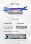
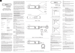
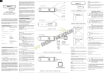
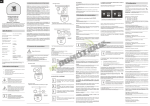
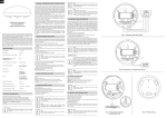
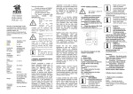
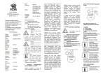
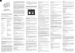
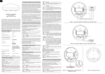
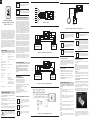
ENG
i
Hint
The outputs of the device should not be loaded with
a current value exceeding 150mA
i
Hint
Connections should be made specifically
according to the diagrams presented in this
manual. Incorrect connection may lead to hazards.
ANT
IN2
GND
TD
}
}
TP
IN2
IN1
I GENERAL INFORMATION ON THE FIBARO SYSTEM
OPERATION MANUAL
UNIVERSAL BINARY SENSOR
FGBS-321-EN-A-v1.00
The Universal Binary Sensor is a wireless module that makes it
possible to improve the functionality of any sensor with a binary
output by allowing it to communicate with the wireless network
Z-WAVE and the FIBARO building intelligence system. Moreover,
the module allows for wireless communication between the system
and the DS18B20 temperature sensors. The device can service up
to two binary sensors and up to four DS18B20 temperature sensors.
The Sensor was designed for installation in the housing of a sensor
or another device, the functionality of which we wish to improve.
The Universal Binary Sensor may be used whenever wireless
collection of data from sensors is required. Once additional safety
housing have been installed, the Sensor can also be used in areas
with high humidity and high temperature. The Sensor’s main function
is the integration of the wireless FIBARO system with the existing
wire-based and wireless alarm and measurement systems. As an
element of the safety system the device is transparent for parametric
alarm lines.
Technical data
Supply voltage:
9-30V DC ±10%
Input:
2 potential-free inputs, 1 digital
input 1-wire
Output:
2 potential-free outputs
Maximum current carrying
capacity of outputs:
150mA
Maximum voltage at output
contacts:
36V DC / 24V AC ±5%
Operating temperature:
0 - 40 °C
Number of servicing
temperature sensors:
4
Measurement range:
-55 C - +126 C
Radio protocol:
Z-Wave
Radio frequency:
o
Dimensions (L x W x H):
P
Although the Z-Wave technology is fairly new, it has already been
accepted as an official standard, just like Wi-Fi. Numerous
manufacturers from various fields offer solutions based on Z-Wave
technology, which are compatible with one another. This makes the
system fit for the future and allows for further development. For
more information go to www.fibaro.com.
IN1
GND
P
NC NC TMP TMP COM 12V
AUX COM Z1
27,3 x 14,5 x 12 mm
Technical information
• Controlled with FIBARO system devices or any Z-Wave controller
• Microprocessor-based control
• Compatible with regular and parametric alarm lines (can be
connected to 2 alarm detectors)
• Compatible with binary sensors (can be connected to 2 binary
Diagram 2 – connection to a regular alarm line
outputs)
i
R1
• In order to connect the DS18B20 sensors it is recommended to use
conductors made from a single wire with a length of up to 30 meters
i
Metal surfaces in close vicinity (e.g. metal
embedded boxes, metal door trims) may impair the
reception capability!
DANGER
The Sensor is powered with secure voltage;
nevertheless, the user should be extra careful or
should commission the installation to a qualified
person.
i
You should not cut off or shorten the antenna. Its
length is suited ideally to the band at which the
system functions.
NC
GND
PRECIPITATION
SENSOR
i
Note!
Do not remove the protective layer surrounding the
module. Make sure that no metal parts of other
devices or conductors come into close contact with
the installed Sensor.
i
Note!
Condition of outputs OUT1 and OUT2 is dependent
only on the condition of corresponding inputs,
irrespective of parameter settings or addition of
device to the Z-wave network.
i
Note!
It should be noted that only the B button starts the
device’s programming process (Include/Exclude).
The DS18B20 sensor may easily be installed wherever very precise
temperature measurements are required. Moreover, if proper
protective measures are undertaken, the sensor may be used in
humid environments or under water, it may be embedded in
concrete or placed under the floor.
B
IN2
IN1
GND
P
GLOSSARY OF TERMS:
• INCLUSION – the device sends out a Node Info frame, which
makes it possible to add it to the Fibaro system (Home Center)
NC TMP TMP COM 12V
MOTION DETECTOR
COM AUX COM Z1
ALARM
SYSTEM HUB
Diagram 3 – connection to a parametric alarm line
• EXCLUSION – removal of device from the Fibaro system
• ASSOCIATION – controlling other devices of the Fibaro system
• MultiChannel Association - controlling other multi-channel
devices of the Fibaro system
III Fibaro Sensor start-up
1. Installation of the Universal Binary Sensor
Module
STEP 1
Connect the device according to the electrical diagram shown in
figure 1. Engage the supply voltage.
[Inclusion / Exclusion] of the Fibaro Sensor [to / from] the Z-Wave
network
i
i
i
Note!
Do not connect other sensors than DS18B20 to the
1-wire line (terminals TP and TD).
Note!
Every time when any changes are made to the
configuration of TP and TD lines (1-wire), e.g. when
DS18B20 sensor(s) is (are) included/excluded, it is
necessary to execute the procedure of exclusion
and repeated inclusion of the sensor module to the
central hub. It should be remembered that the
system shall enter into the programming mode only
once all the connected sensors have been
detected (about 10 s).
Note!
It is prohibited to connect the TP and TD lines to
devices that are not compatible with the 1-wire
protocol. Unused lines should be left insulated.
2. Resetting the Fibaro Sensor
There are two procedures you can follow in order to reset the
Fibaro Sensor.
Method I
Resetting in the course of the procedure of excluding the Fibaro
Module from an existing Z-wave network. Devices may be excluded
with the use of a controller, which offers the option to exclude
devices from or include devices to the Z-wave network (see:
controller instructions).
Method II
Resetting by cutting off the power supply and re-connecting the
power supply while holding down the B button – after 10 seconds,
after another cut-off and re-connection of power supply the settings
of the device will be reset.
3. Controlling the Fibaro Sensor with the Home
Center 2 controller
The FGBS221 Sensor is a multi-channel device. This means that it
is equipped with two independent input circuits and a 1-wire bus
allowing it to be connected to four DS18B20 temperature sensors.
As a result, each device connected to the Sensor is represented by
an independent icon in the system.
After the Fibaro Sensor has been added to the network, it shall be
represented by appropriate icons in the Home Center 2 controller,
depending on the number of connected devices (3 – 7 icons).
STEP 2
The Fibaro Module must be in range of the Home Center 2
controller, because the procedure of inclusion to the Fibaro system
requires direct communication with the controller.
STEP 3
Recognition of B button, which allows for proper inclusion of device.
STEP 4
Setting the Home Center 2 controller to the inclusion or exclusion
mode (see: Home Center 2 controller instructions).
• Compatible with DS18B20 temperature sensors (can be connected
to four DS18B20 temperature sensors)
NO
INSTRUCTIONS FOR ARRANGEMENT
OF THE DS18B20 SENSOR:
ANTENNA ARRANGEMENT INSTRUCTIONS:
Lay down the antenna as far as possible from
metal elements (connection conductors, ring
brackets etc.), in order to prevent any interference
of the radio signal.
Z2
ALARM
SYSTEM HUB
MOTION DETECTOR
NC
P – (POWER) – power supply conductor, red
GND - (GROUND) – ground conductor, blue
OUT1 – output no. 1 assigned to input IN1
OUT2 – output no. 2 assigned to input IN2
TP – (TEMP_POWER) – power supply conductor of the DS18B20
temperature sensor, brown (3.3V)
TD – (TEMP_DATA) – signal conductor of the DS18B20
temperature sensor, white
ANT – antenna, black
OUT1 – output no. 1 assigned to input IN1
OUT2 – output no. 2 assigned to input IN2
B – maintenance button (used to add devices to and remove
devices from the system)
OUT 1
B
IN2
o
868,4 MHz for EU;
908,4 MHz for US;
921,4 MHz for AUS/NZ/BRA
GND
NC
Diagram 5 – example connection to a precipitation sensor
R2
EXPLANATION OF
CONDUCTOR MARKINGS:
OUT 2
BELL-PUSH
FIBARO establishes a dynamic network structure. From the
moment of start-up, the location data of respective devices of the
FIBARO system is updated automatically, in real time, by
confirming their condition in the working „mesh” network.
1. Before the installation make sure to switch off the alarm
system, or any other system to which the device is to be
connected.
2. Connect the Fibaro Sensor according to the diagram.
3. Place the Fibaro Sensor in the sensor housing.
4. Arrange the antenna (instructions can be found below the
diagrams).
+9 - 30V
Diagram 1 – general
II. Sensor Installation
up to 30 m in buildings
(depending on the construction
materials) up to 50m in the field
Range:
FIBARO operates in the free band for data transmission. The
frequency depends on radio regulations in individual country . Each
FIBARO network has its own unique network identification number
(home ID), which is why it is possible to co-operate two or more
independent systems in a single building without any interference.
P
GND
FIBARO is a system that does not require any additional
conductors; it is based on the Z-Wave technology. FIBARO offers a
wide array of advantages in comparison to other, similar systems.
In general, radio-based systems establish a direct connection
between the receiver and the transmitter. The radio signal is
attenuated by every obstacle along its path (in the household e.g.
walls, furniture, etc.). In the worst case the radio system ceases to
function. The advantage of the FIBARO system is the fact that the
devices act not only as a signal receiver and transmitter, but also as
a signal “repeater”. If a direct radio link between the transmitter and
the receiver cannot be established, the connection will be carried
out with the use of other devices participating in communication.
FIBARO is a bidirectional wireless system. This means that the
signal is not only sent to the receivers, but also the receivers send
feedback confirming the reception of the signal. This also confirms
the condition of receivers, which allows us to check whether or not
a device has actually been switched on. The safety of transmission
of the FIBARO system is comparable with a wire-linked bus system.
B
B
IN1
Diagram 4 – connection to DS18B20 sensors
STEP 5
The Fibaro Sensor is added to the network by quickly pressing the
B button three times (the button is located in the center of the
device).
Fig. 1 - Fibaro Sensor icon in the Home Center controller
STEP 6
Correct inclusion of the device to the network will be signaled by
Home Center 2 (see: Home Center 2 central hub operation
instructions).
In the event of including the Sensor without any sensors connected
(or with sensors connected only to IN1 and IN2), the device will be
represented by three icons. If DS18B20 sensors are also
connected, the devices will be represented by additional
temperature icons.
i
Note!
If the number of temperature sensor icons is
different than the actual number of sensors
connected to the device, or if the temperature
readings are incorrect, you should inspect the
connections on the 1-wire bus, in particular the
connection between respective sensor outputs and
the line and the total length of the bus (bus bar),
which should not exceed 30m.
Parameter no. 4
Type of input no. 2:
Default value: 1 - INPUT_NC (Normal Close)
Possible parameter settings:
0 – INPUT_NO (Normal Open)
1 – INPUT_NC (Normal Close)
2 – INPUT_MONOSTABLE
3 – INPUT_BISTABLE
Parameter no. 5
IV Association
Association allows the Fibaro Sensor to directly control another
device of the Z-wave network, e.g. Dimmer, Switch (ON-OFF),
Roller Shutter or scenes (scene control is only possible via the
Home Center 2 controller).
i
NOTE!
Association allows for direct transmission of control
commands between devices and takes place
without the participation of the main controller.
Owing to this mechanism the Sensor may
communicate with devices even if the central
control hub is completely destroyed, e.g. in the
event of a fire.
The Fibaro Sensor makes it possible to configure three
association groups.
Group I is assigned to input IN1
Group II is assigned to input IN2
Group III reports on the condition of the device, only one device
may be assigned to the group.
The Fibaro Sensor allows for control over 5 regular devices and 5
multi-channel devices per group, out of which 1 field is reserved for
the network controller.
In order to add an association (with the use of the Home Center 2
controller) go to device options by clicking this icon:
Select the “device options” tab. Next, specify which devices will be
associated and with which groups. Sending of changed
configuration to the device might take couple of seconds.
V Configuration
The Universal Binary Sensor offers a wide range of advanced
settings, the parameters listed below are available in the
Fibaro configuration interface.
In order to configure the Fibaro Sensor (using the Home Center 2
controller) go to the device options by clicking on the icon:
Next, select the “device options” tab.
Device parameters:
Parameter no. 1
Input I alarm cancellation delay. Additional delay after an alarm
from input IN1 has ceased. The parameter allows you to specify
additional time, after which the input no. 1 alarm is cancelled once
its violation has ceased.
Default value: 0
Possible parameter settings: 0 – 65535 s
Parameter 2 [byte]
Parameter no. 2
Input II alarm cancellation delay. Additional delay after an alarm
from input IN2 has ceased. The parameter allows you to specify
additional time, after which the input no. 2 alarm is cancelled once
its violation has ceased.
Default value: 0
Possible parameter settings: 0 – 65535 s
Parameter 2 [byte]
Type of transmitted control frame for association group 1, activated
via input IN1. The parameter allows to specify the type of alarm
frame or to force transmission of control commands (BASIC_SET)
Default value: 255 – BASIC SET
Possible parameter settings:
0 – Frame ALARM GENERIC
1 – Frame ALARM SMOKE
2 – Frame ALARM CO
3 – Frame ALARM CO2
4 – Frame ALARM HEAT
5 – Frame ALARM WATER
255 – Control frame BASIC_SET
Parameter no. 6
Type of transmitted control frame for association group 2, activated
via input IN2. The parameter allows to specify the type of alarm
frame or to force transmission of control commands (BASIC_SET)
Default value: 255 - BASIC SET
Possible parameter settings:
0 – Frame ALARM GENERIC
1 – Frame ALARM SMOKE
2 – Frame ALARM CO
3 – Frame ALARM CO2
4 – Frame ALARM HEAT
5 – Frame ALARM WATER
255 – Control frame BASIC_SET
Parameter no. 7
Value of the parameter specifying the forced level of dimming /
opening sun blinds when comes “switch on” / ”open” command to
devices from association group no. 1.
In the case of alarm frames the alarm priority is specified.
Default value: 255
Possible parameter settings: (1 – 99) and 255
Value of 255 makes it possible to activate the device when using
the Dimmer module it means activating the device and setting it to
the previous stored condition, e.g. when Dimmer is set to 30%, then
deactivated, and then reactivated using command 255, it will
automatically be set to the previous condition, i.e. 30%.
Parameter no. 8
Value of the parameter specifying the forced level of dimming /
opening sun blinds when comes “switch on” / ”open” command to
devices from association group no. 2.
In the case of alarm frames the alarm priority is specified.
Default value: 255
Possible parameter settings:
(1 – 99) and 255
Value of 255 makes it possible to activate the device; when using of
the Dimmer module it means activating the device and setting it to
the previous stored condition, e.g. when Dimmer is set to 30%, then
deactivated, and then reactivated using command 255, it will
automatically be set to the previous condition, i.e. 30%.
Parameter no. 9
Deactivating transmission of the frame cancelling the alarm or the
control frame deactivating the device (Basic). It allows for disabling
the deactivation function or the alarm cancellation function for
devices associated with the appropriate input of the Fibaro Sensor.
Default value: 0, in the case of association group no. 1 and 2 the
information is sent
Possible parameter settings:
0 – in the case of association group no. 1 and 2 the information is
sent
1 – in the case of association group no. 1 the information is sent. In
the case of association group no. 2 the information is not sent.
2 – in the case of association group no. 1 the information is not
sent. In the case of association group no. 2 the information is sent.
NOTE: Information concerning alarm violation or activation
commands for devices from association groups are always
sent.
Parameter no. 10
Parameter no. 3
Type of input no. 1:
Default value: 1 – INPUT_NC (Normal Close) Possible parameter
settings:
0 – INPUT_NO (Normal Open)
1 – INPUT_NC (Normal Close)
2 – INPUT_MONOSTABLE
3 – INPUT_BISTABLE
Interval between successive readings of temperature from all
sensors connected to the device.
Default value: 20 s
Possible parameter settings:
1 – 255 s
Note: taking temperature readings from the sensor does not
result in sending a temperature condition report to the central
hub.
Parameter no. 11
Interval between forcing to send report concerning the temperature
conditions. The forced report is sent immediately after the next
reading of temperature from the sensor, irrespective of the settings
of parameter no. 12.
Default value: 200 s
Possible parameter settings:
0 – 255 s
0 – deactivating the function
Note: Frequent sending of temperature condition reports is
reasonable when the sensor is located somewhere where can
occure rapid changes of ambient temperature. In other cases
it is recommended to leave the parameter set to the default
value.
Parameter no. 12
Insensitiveness to temperature changes. This is the maximum
acceptable difference between the last reported temperature and
the current temperature taken from the sensor. If the temperatures
differ by the set value or more, then a report with the current
temperature value is sent to the device assigned to association
group no. 3. Intervals between taking readings from sensors are
specified by parameter no. 10.
Default value: 8 [0.5oC]
Possible parameter settings:0 – 255 [0oC to 16oC] [0 oF – 28.8oF]
In order to set the appropriate value of the parameter, the following
formula should be used:
x = delta T x 16 - for Celsius
x = delta T x 80 / 9 - for Fahrenheit
x – parameter value
delta T – maximum acceptable temperature gradient in Celsius or
Fahrenheit
If the value is set to 0, then information about the temperature will
be sent every time, immediately once the readings have been taken
from the sensor.
VI Additional functionality
Alarm frame servicing
The Fibaro system makes it possible to set the device’s reaction to
alarm events (reaction to the frame SENSOR_ALARM_REPORT).
The Fibaro Sensor transmits alarm frames of different types,
depending on the settings in parameters no. 5 and 6. The user
should correctly declare the type of alarm frame for each connected
sensor (inputs IN1 and IN2). For example, for a smoke detector
connected to input IN1 the user should declare the frame type 1 –
ALARM SMOKE (value of 1 should be entered), to ensure that the
remaining devices will correctly recognize information on smoke
detector alarm.
VII Sensor operation
The Fibaro Sensor may be operated with the following operator
elements:
• Any controller compatible with the system (e.g. Home Center 2
controller)
• Cellular phone (e.g. iPhone or phones of other manufacturers with
the proper control application)
• PC, with the use of an Internet browser
• Tablet devices (e.g. iPad)
• With the use of the maintenance button B located inside the
housing
VIII Procedure to be followed in the
case of interference
The Device does not react to a programmed transmitter:
• Make sure that the maximum range was not exceeded and that
there are no obstacles along the signal path which contain metal
surfaces, e.g. metal cabinets, ferroconcrete ceiling and load
bearing walls, etc.
• Make sure that the device is not in the programming mode.
• Possibly repeat the programming process.
Parameter no. 13
Transmitting the alarm or control frame in “broadcast” mode (i.e. to
all devices within range), information sent in this mode is not
repeated by the mesh network.
Default value: 0
Possible parameter settings:
0 – IN1 and IN2 Broadcast inactive
1 – IN1 broadcast mode active, Sensor 2 broadcast mode inactive
2 – IN1 broadcast mode inactive, Sensor 2 broadcast mode active
3 – INI and IN2 broadcast mode active
NOTE!
If the “broadcast” mode of information transmission is
activated for a given channel, then transmission of
information in “singlecast” mode to devices assigned to the
association group of this channel is deactivated.
Parameter no. 14
Scene activation functionality.
Default value: 0
Possible parameter settings:
0 – deactivation of functionality
1 – activation of functionality
The device offers the possibility of sending commands compatible
with Command class scene activation. Information is sent to
devices assigned to association group no. 3.
Controllers such as Home Center 2 are able to interpret such
commands and basing on these commands they activate scenes,
to which specific scene IDs have been assigned. The user may
expand the functionality of the button connected to inputs IN1 and
IN2 by distinguishing the actions of keys connected to those inputs.
For example: double click would activate the scene “goodnight” and
triple click would activate the scene “morning”.
Scene ID is assigned in the following manner:
input IN1:
switch from “off” to “on” ID 10
switch from “on” to “off” ID 11
remaining IDs are recognized correctly if the value of parameter no.
3 was set to 2
holding down ID 12
releasing ID 13
double click ID 14
triple click ID 15
input IN2:
switch from “off” to “on” ID 20
switch from “on” to “off” ID 21
remaining IDs are recognized correctly if the value of parameter no.
4 was set to 2
holding down ID 22
releasing ID 23
double click ID 24
triple click ID 25
NOTE!!! Inputs IN1 and IN2 are used to control the condition of
the device. Each of them may force two conditions for
corresponding device channels: on / alarm, off / no alarm. If
monostable keys are used and the value of parameter no. 3 or
no. 4 is set to 2, change of the state of corresponding channel
will be able after a single click.
IX GUARANTEE
1. The Guarantee is provided by FIBAR GROUP Sp. z o.o.
(hereinafter "Manufacturer"), based in Poznan, ul. Lotnicza 1;
60-421 Poznan, entered in the register of the National Court
Register kept by the District Court in Poznań, VIII Economic
Department of the National Court Register, no. 370151, NIP
7811858097, REGON: 301595664.
2. The Manufacturer is responsible for equipment malfunction
resulting from physical defects (manufacturing or material) of the
Device for 12 months from the date of its purchasing.
3. During the Guarantee period, the Manufacturer shall remove any
defects, free of charge, by repairing or replacing (at the sole
discretion of the Manufacturer) any defective components of the
Device with new or regenerated components, that are free of
defects. When the repair impossible, the Manufacturer reserves the
right to replace the device with a new or regenerated one, which
shall be free of any defects and its condition shall not be worse than
the original device owned by the Customer.
4. In special cases, when the device cannot be replaced with the
device of the same type (e.g. the device is no longer available in the
commercial offer), the Manufacturer may replace it with a different
device having technical parameters similar to the faulty one. Such
activity shall be considered as fulfilling the obligations of the
Manufacturer. The Manufacturer shall not refund money paid for the
device.
5. The holder of a valid guarantee shall submit a guarantee claim
through the guarantee service. Remember: before you submit a
guarantee claim, contact our technical support using telephone or
e-mail. More than 50% of operational problems is resolved
remotely, saving time and money spent to initiating guarantee
procedure. If remote support is insufficient, the Customer shall fill
the guarantee claim form (using our website - www.fibargroup.com)
in order to obtain claim authorization.
When the guarantee claim form is submitted correctly, the
Customer shall receive the claim confirmation with an unique
number (Return Merchandise Authorization -RMA).
6. The claim may be also submitted by telephone. In this case, the
call is recorded and the Customer shall be informed about it by a
consultant before submitting the claim. Immediately after submitting
the claim, the consultant shall provide the Customer with the claim
number (RMA-number).
7. When the guarantee claim form is submitted correctly, a
representative of the Authorised Guarantee Service (hereinafter as
"AGS") shall contact the Customer.
8. Defects revealed within the guarantee period shall be removed
not later than 30 days from the date of delivering the Device to AGS.
The guarantee period shall be extended by the time in which the
Device was kept by AGS.
9. The faulty device shall be provided by the Customer with
complete standard equipment and documents proving its purchase.
10. Parts replaced under the guarantee are the property of the
Manufacturer. The guarantee for all parts replaced in the guarantee
process shall be equal to the guarantee period of the original
device. The guarantee period of the replaced part shall not be
extended.
11. Costs of delivering the faulty device shall be borne by the
Customer. For unjustified service calls, the Service may charge the
Customer with travel expenses and handling costs related to the
case.
12. AGS shall not accept a complaint claim only when:
• the Device was misused or the manual was not observed,
• the Device was provided by the Customer incomplete, without
accessories or nameplate,
• it was determined that the fault was caused by other reasons than
a material or manufacturing defect of the Device
• the guarantee document is not valid or there is no proof of
purchase,
13. The Manufacturer shall not be liable for damages to property
caused by defective device. The Manufacturer shall not be liable for
indirect, incidental, special, consequential or punitive damages, or
for any damages, including, inter alia, loss of profits, savings, data,
loss of benefits, claims by third parties and any property damage or
personal injuries arising from or related to the use of the Device.
14. The guarantee shall not cover:
• mechanical damages (cracks, fractures, cuts, abrasions, physical
deformations caused by impact, falling or dropping the device or
other object, improper use or not observing the operating manual);
• damages resulting from external causes, e.g.: flood, storm, fire,
lightning, natural disasters, earthquakes, war, civil disturbance,
force majeure, unforeseen accidents, theft, water damage, liquid
leakage, battery spill, weather conditions, sunlight, sand, moisture,
high or low temperature, air pollution;
• damages caused by malfunctioning software, attack of a
computer virus, or by failure to update the software as recommended by the Manufacturer;
• damages resulting from: surges in the power and/or telecommunication network, improper connection to the grid in a manner
inconsistent with the operating manual, or from connecting other
devices not recommended by the Manufacturer.
• damages caused by operating or storing the device in extremely
adverse conditions, i.e. high humidity, dust, too low (freezing) or too
high ambient temperature. Detailed permissible conditions for
operating the Device are defined in the operating manual;
• damages caused by using accessories not recommended by the
Manufacturer
• damages caused by faulty electrical installation of the Customer,
including the use of incorrect fuses;
• damages caused by Customer's failure to provide maintenance
and servicing activities defined in the operating manual;
• damages resulting from the use of spurious spare parts or
accessories improper for given model, repairing and introducing
alterations by unauthorized persons;
• defects caused by operating faulty Device or accessories.
15. The scope of the guarantee repairs shall not include periodic
maintenance and inspections, in particular cleaning, adjustments,
operational checks, correction of errors or parameter programming
and other activities that should be performed by the user (Buyer).
The guarantee shall not cover natural wear and tear of the Device
and its components listed in the operating manual and in technical
documentation as such elements have a defined operational life.
16. If a defect is not covered by the guarantee, the Manufacturer
reserves the right to remove such defect at its sole discretion,
repairing the damaged or destroyed parts or providing components
necessary for repair or replacement.
17. This guarantee shall not exclude, limit or suspend the Customer
rights when the provided product is inconsistent with the purchase
agreement.
i
This Device may be used with all devices
certified with Z-Wave certificate and should be
compatible with such devices produced by
other manufacturers.
Any device compatible with Z-Wave may be added
to Fibaro system.
FIBARGROUP
FIBARO
In case of any technical questions contact customer service centre
in your country.
www.fibargroup.com