1
KRAMER ELECTRONICS, Ltd.
USER MANUAL
Vertical Interval Switchers
MODELS: VS-1211, VS-1011, VS-811, VS-611, VS-411
With Balanced Audio
VS-1201xl, VS-1001xlm, VS-801xlm, VS-601xlm, VS-401xlm
With Unbalanced Audio
IMPORTANT: Before proceeding, please read paragraph entitled
"Unpacking and Contents"
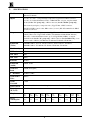
Table of Contents
Section
.1
.1.1
.1.2
.
Name
Page
INTRODUCTION
A Word On Video/Audio Switchers
Factors Affecting Quality of Results
SPECIFICATIONS
HOW DO I GET STARTED
UNPACKING AND CONTENTS
Optional Accessories
KRAMER “VS” SERIES SWITCHERS
Getting to Know Your Switcher
INSTALLATION
Rackmounting
CONNECTING TO VIDEO DEVICES
Connecting to the VS-1211/1201xl/1001xlm
CONNECTING TO AUDIO DEVICES
Connecting to the VS-1211
Connecting to the VS-1201xl
DIP SWITCHES, JUMPERS AND TRIMMERS
DIP Switches
Jumpers, their Uses and Set-up Requirements
The Internal Trimmers
CONTROLLING THE SWITCHER
The VS-2000 System
The VS-1N/VS-1P System
CONNECTING TO A PC
New Protocol 2000
Changing Communication Protocols
Additional Software Options
USING THE SWITCHER
Powering on the Switcher
Operating an Individual Switcher
Selecting an Input on the Switchers
Selecting the Proper Sync Format
Using the VS-2000
Using the PC Control Software
Adding Outputs
Adding Inputs
Video Component and YC Switching
Controlling Several Independent Switchers via a Single PC Port
TAKING CARE OF YOUR SWITCHER
TROUBLESHOOTING
Power and Indicators
Video Signal
Audio Signal
Software
Control
Switching Malfunctions
Vertical Interval
PROTOCOL USED FOR VS-1211 1201xl COMMUNICATION
Limited Warranty
KRAMER ELECTRONICS LTD.
2
4
4
5
6
7
7
7
8
9
11
11
11
11
11
11
11
11
11
12
14
14
14
14
16
16
16
24
Table of Contents (Continued)
List of Illustrations
Figure
Page
RS-232 Control Connector Wiring
VS-1211/1201 Front/Rear Panel Features
Location of Internal Jumpers
VS-Series Remote Connector Socket and Balanced Audio Pinout
Connecting Two Switchers to add Outputs
8
9
3
5
8
List of Tables
Table
VS-1211/1201 Front Panel Features
VS-1211/1201 Rear Panel Features
DIP Switch Settings
KRAMER ELECTRONICS LTD.
10
10
12
3
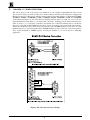
ADDENDUM: VS-1211, VS-1011, VS-811, VS-611, VS-411 User Manual
The following section is added to the manual as follows:
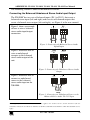
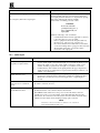
Connecting the Balanced/Unbalanced Stereo Audio Input/Output
The VS-12111 has two sets of balanced inputs (IN 1 to IN 12) that create a
balanced stereo input (left and right) and two sets of balanced outputs that
create a balanced stereo output (left and right), see Figure 4 in the user manual.
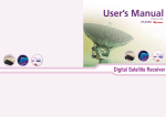
Figure 1 shows an example
of how to wire a balanced
stereo audio input/output
connection
+
-
+
-
G
Figure 1: Connecting the Balanced Stereo Audio
Input/Output
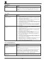
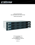
Figure 2 illustrates how to
wire an unbalanced
acceptor to the balanced
stereo audio output of the
unit:
+
-
+
G
-
Figure 2: Connecting the Unbalanced Stereo Audio
Output
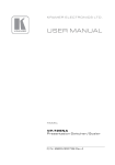
Figure 3 illustrates how to
connect an unbalanced
source to the balanced
stereo audio input on the
VS-1211:
+
-
+
G
-
L G R
Figure 3: Connecting an Unbalanced Source to the
Balanced Stereo Audio VS-1211 Input
1 Although only VS-1211 is mentioned, this section also applies to the VS-1011, VS-811, VS-611 and VS-411 (the user
manual also includes the VS-1201xl, VS-1001xlm, VS-801xlm, VS-601xlm and VS-401xlm to which this addendum does not
apply)
P/N: 2900 - 0020021
A1
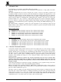
1.
INTRODUCTION
Congratulations on your purchase of this Kramer Electronics switcher.
Since 1981 Kramer has been dedicated to the development and manufacture of high quality video/audio
equipment.
The Kramer industrial line has become an integral part of many of the best video/audio production and
presentation facilities around the world. In recent years, Kramer has redesigned and upgraded most of the
industrial line, making the best even better. Kramer’s line of professional video electronics is one of the most
versatile and complete available, and is a true leader in terms of quality, workmanship, price/performance ratio
and innovation. In addition to the Kramer line of high quality video switchers, such as the one you have just
purchased, Kramer also offers a full line of high quality industrial and broadcast distribution amplifiers,
processors, interfaces, controllers and computer-related products. Kramer welcomes your inquiries for Kramer
equipment or custom-manufactured products, engineering, private labeling and OEM manufacturing per your
specifications.
This manual includes configuration, operation and option information for the following products from the
Kramer VS line of video switchers. These VS switchers are similar in operation and features and differ in their
audio input and output type.
Balanced Audio Family:
VS-1211- 12x1 composite/single component video & balanced audio switcher.
VS-1011- 10x1 composite/single component video & balanced audio switcher.
VS-811- 8x1 composite/single component video & balanced audio switcher.
VS-611- 6x1 composite/single component video & balanced audio switcher.
VS-411- 4x1 composite/single component video & balanced audio switcher.
Unbalanced Audio Family:
VS-1201xl- 12x1 composite/single component video & unbalanced audio switcher.
VS-1001xlm- 10x1 composite/single component video +DA & unbalanced audio switcher.
VS-801xlm- 8x1 composite/single component video +DA & unbalanced audio switcher.
VS-601xlm- 6x1 composite/single component video +DA & unbalanced audio switcher.
VS-401xlm- 4x1 composite/single component video +DA & unbalanced audio switcher.
1.1
A Word on Video/Audio Switchers
A video/audio switcher usually switches between several sources (inputs) and one or more acceptors (outputs).
A switcher that allows several inputs to be connected to several outputs simultaneously is called a Matrix
Switcher. Switchers may be of the electronic or mechanical type. Most matrices are of the active electronic type,
with many crosspoints. Vertical Interval Switching, frequently used in video, ensures that the transition from
one video source to another (such as switching between two genlocked cameras) is smooth and without
interference. The switching and changeover is done during the blanked vertical interval period, when the
transition is hidden.
Genlocked means synchronized so that the color and phase information from each source is identical. Thus
switching is done with no interference, no rolling, no color loss and no jumping on the screen. Since the
Syncs come with the same timing, all the information is identical and the transition between one source and
the other is smooth.
Vertical Interval Switching is needed when recording or transmitting a video program involving several video
sources, as in live broadcast, to ensure clean, undisturbed picture transitions.
Matrices and switchers may sometimes be RS-232 or RS-485/422 controlled. Each of these options is a way of
remotely controlling a video/audio device (switcher, SEG, etc.) using a PC with a serial port, or another device
that uses a similar communication protocol.
The range consists of a number of models, having between twelve and four inputs, as indicated by the model
name. The audio output is either balanced or unbalanced. Switching is effortless and is performed during the
vertical interval of source #1, or of the video available at the external Sync socket. The switchers can be
controlled by touch buttons on the front panel, by a PC, via the switcher'
s built-in RS-232 and/or RS-485/422
communication ports, or by contact closure via a remote socket on the back panel.
KRAMER ELECTRONICS LTD.
4
All the models can be interconnected in a variety of ways. For example, two VS-1211 units become 24x1 or
12x2, etc. Three or four VS-1211 units, depending on whether the system is RGB or RGBS, become a 12x1
video component switcher. Finally, the video signal bandwidth is 225MHz (typical), which permits the
switchers to be used in the most demanding applications.
1.2
Factors Affecting Quality of Results
There are many factors affecting the quality of results when signals are transmitted from a source to an acceptor:
Connection cables - Low quality cables are susceptible to interference, they degrade signal quality due to
poor matching and cause elevated noise levels. They should therefore be of the best quality.
Sockets and connectors of the sources and acceptors - So often ignored, they should be of highest
quality, since "Zero Ohm" connection resistance is the target. Sockets and connectors also must match the
required impedance (75ohms in video). Cheap, low quality connectors tend to rust, thus causing breaks in the
signal path.
Amplifying circuitry - Must have quality performance when the desired end result is high linearity, low
distortion and low noise operation.
Distance between sources and acceptors - Plays a major role in the final result. For long distances (over
15 meters) between sources and acceptors, special measures should be taken in order to avoid cable losses.
These include using higher quality cables or adding line amplifiers.
Interference from neighboring electrical appliances - These can have an adverse effect on signal quality.
Balanced audio lines are less prone to interference, but unbalanced audio and video lines should be installed
far from any mains power cables, electric motors, transmitters, etc. even when the cables are shielded.
KRAMER ELECTRONICS LTD.
5
2.
SPECIFICATIONS
Models
VS-1211, VS-1011, VS-811, VS-611, VS-411, VS-1201xl, VS-1001xlm, VS-801xlm, VS601xlm, VS-401xlm
Inputs
12, 10, 8, 6, 4 video - composite/single component, 1Vpp/75ohm on BNC connectors.
12, 10, 8, 6, 4 balanced/unbalanced audio, +4dBm/10kohm, on 2-part, snap fit terminal
blocks (for the "11" group only), or RCA connectors (for the "01xl/m" group only).
One external sync input (or composite video) 1Vpp/75ohm, on BNC connector.
One RS-232 DB-9 control socket, DB-9 socket (“to next”), RS-485 terminal block, DB-15
for remote connector.
Outputs
One video - composite/single component, 1Vpp/75ohm on BNC connector (VS-1211, VS1201xl), Three video 1Vpp/75ohm on BNCs (VS-1001xlm, 801xlm,601xlm, 401xlm.)
One audio – balanced/unbalanced audio, up to +28Vpp/50ohm (24dBm), on snap fit
terminal blocks (for the "11" group only) or RCA connector (for the 1201xl only), 3 sets
of stereo audio on RCAs (VS-1001xlm, VS-801xlm, VS-601xlm, VS-401xlm.)
Bandwidth
(Video)
250 MHz -3dB for VS-1211, VS-1011, VS-811, VS-611, VS-411, VS-1201xl.
Non-linearity
<0.1%.
S/N Ratio
>77dB.
Diff. Phase
0.03
Diff. Gain
0.04%
K-Factor
<0.05%
Bandwidth
(Audio)
55kHz, -0.ldB.
Audio S/N
Ratio
>95dB (unweighted)
2nd Harmonic
<0.003% (1kHz)
Audio THD +
Noise
0.013%
Audio
Crosstalk
-79dB
Video Controls
Bottom accessible trimmers for video gain (-1.2 to 1.8dB Luma), cable EQ. (0 to 1.3dB)
Dimensions
(W, D, H)
19" x 7" x 1U rack mountable
Weight
Power
consumption
Power Source
400 MHz -3dB for VS-1001xlm, VS-801xlm, VS-601xlm, VS-401xlm.
VS-1211
3.1kg
(~7lbs)
VS-1011
2.9kg
(~6.6lbs)
VS-811
2.9kg
(~6.5lbs)
VS-611
2.88kg
(~6.4lbs)
VS-411
2.68kg
(~5.9lbs)
VS-1201xl
3.1kg
(~7lbs)
VS-1001xlm VS-801xlm VS-601xl
2.9kg
2.9kg
m 2.88kg
(~6.6lbs)
(~6.5lbs)
(~6.4lbs)
VS-401xl m
2.68kg
(~5.9lbs)
16VA
15VA
16.1VA
18.4VA
19.5VA
16VA
15VA
19.5VA
230VAC, 50/60 Hz (115VAC U.S.A.)
KRAMER ELECTRONICS LTD.
6
16.1VA
18.4VA
3.
HOW DO I GET STARTED?
The fastest way to get started is to take your time and do everything right the first time. Taking 15 minutes to
read this manual may save you a few hours later. You don’t even have to read the whole manual. At the
beginning of each section, you’ll find an overview of the section. So if the section doesn’t apply to you, you
don’t have to spend your time reading it.
4.
UNPACKING AND CONTENTS
The items contained in your Kramer VS switcher package are listed below. Please save the original box and
packaging materials for possible future transportation and shipment of the video switcher.
This User Manual
Your KRAMER Switcher
A Power Cord
KRAMER K-Switch Software for Windows 95/98® (A CD plus Booklet or download from the web)
KRAMER Null Modem Adapter Connector
A Concise Directory of KRAMER Products
4.1
Optional Accessories
The following accessories, which are available from Kramer, can enhance implementation of your amplifier.
For information regarding cables and additional accessories, contact your Kramer dealer.
BNC "Y" Connector - Used for looping purposes and splits the incoming signal to enable connection of
an additional machine.
SP-11 - (Video/Audio Processor) can be serially connected between the video/audio source and the
switcher for video and audio control/correction. The machine provides camera control and luminance/white
balance correction. The SP-11 is also capable of performing composite to Y/C conversion and bi-directional
transcoding. The machine allows full control over the video signal: video gain down to full fade, log or linear
definition control, log or linear contrast control, color saturation control, black level control, red, green and
blue controls and a screen splitter control for “before-after” comparison. The Input switch control is "audiofollow-video".
VM-1411 (Video/Balanced Stereo Audio Distribution Amplifier) can be serially connected between the
switcher and the acceptors for video and audio distribution. It is a full broadcast, state-of-the-art machine,
designed for studio and other applications. The VM-1411 has two inputs, video and audio, each splitting to 5
outputs. The user may select 2 x 1:5 or 1:10 operation via front panel control switches. Several VM-1411
units may be chained through the looping inputs. Output signals are (user selectable) DC or AC coupled for
highest flexibility. Audio outputs are buffered and isolated from each other, allowing Hi-Fi Balanced audio
distribution.
VIDEO TESTER - A new, unique, patented, indispensable tool for the video professional, the video
Tester is used to test a video path leading to/from an amplifier. By pressing only one touch switch it can trace
missing signals, distinguish between good and jittery (VCR sourced) signals, and identify the presence of
good signals. Whenever a video signal is missing, because of bad connections, cable breaks or faulty sources,
the video Tester is all you need.
KRAMER ELECTRONICS LTD.
7
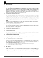
5.
KRAMER “VS” SERIES SWITCHERS
This section shows you all of the controls and connections of your switcher. Understanding all of the controls
and connections helps you realize its full power. All the switchers described in this manual are equipped with
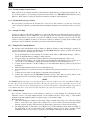
RS-232 Connectors (for PC control) and the connector wiring is described in Figure 1. The Kramer VS-1211,
VS-1201xl, VS-1011, VS-1001xlm, VS-811, VS-801xlm, VS-611, VS-601xlm, VS-411 and VS-401xlm
Vertical Interval Switchers provide truly effortless switching between twelve, ten, eight, six or four video and
balanced/unbalanced audio inputs to one output (video and audio). Switching is done during vertical interval,
either of source no. 1 or of the video connected to the external sync socket. The switchers may be controlled in
three ways: touch buttons, RS-232/RS-485 and contact closure via a remote socket on the back of the machines.
All the units in this line can be interconnected and cascaded, (two VS-1211 machines become 24x1, etc.) The
machines may also be operated in parallel (three VS-1211 machines become a 12x3 video component switcher).
Video signal bandwidth is 250MHz (typical), allowing the machines to be used in the most demanding
applications.
Figure 1: RS-232 Control Connector Wiring
KRAMER ELECTRONICS LTD.
8
5.1
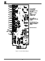
Getting to Know Your Switcher
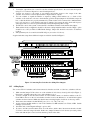
Most front/rear panel features of the switchers described in this manual are very similar. Therefore, only the VS1211 and the VS-1201xl are described and they represent the rest of the switchers. The main difference is that
the “11” group has snap fit terminal block connectors for balanced audio and the “01xl” group has RCA
connectors for unbalanced audio.
Front/rear panel features of the VS-1211 and VS-1201xl/VS-1001xlm switchers are described in Figure 2, Table
and Table .
Figure 2: VS-1011xlm/VS-1201xl Front/Rear Panel Features
KRAMER ELECTRONICS LTD.
9
Table : VS-1211/1201/1001xlm Front Panel Features
No.
Feature
Function
1.
2.
POWER Switch
INPUT SELECTOR pushbuttons
3.
Internal cable EQ. trimmer
4.
Internal LEVEL trimmer
Illuminated switch: Supplies power to the unit.
Each input may be selected by the corresponding input select button.
The buttons illuminate when pressed and the illuminated input select
button identifies the active input.
Internally located and accessed through hole in the switcher base. It
allows, if necessary, to control cable equalization.
Internally located and accessed through hole in the switcher base. It
allows, if necessary, to adjust switcher output signal level.
Table : VS-1211/1201/1001xlm Rear Panel Features
No.
Feature
1.
6.
7.
AUDIO L snap fit terminal blocks
for the "11" group or RCA
connectors for the “01xl” group.
OUT L snap fit terminal blocks for
the "11" group or RCA connector
for the “01xl” group.
RS-485 Two-part, snap fit terminal
block
AUDIO R snap fit terminal blocks
for the "11" group or RCA
connectors for the “01xl” group.
OUT R snap fit terminal blocks for
the "11" group or RCA connector
for the “01xl” group.
Ext. Sync BNC connector
IN1-IN12 BNC connectors
8.
OUT BNC connector (s)
9.
DB-9 female To PC connector
10.
11.
12.
REMOTE DB-15 connector
To Next DB-9 connector
SETUP DIP switches
13.
Power Connector
2.
3.
4.
5.
KRAMER ELECTRONICS LTD.
Function
12, 10, 8, 6 or 4 left channel inputs used to connect the appropriate
number of stereo audio input sources 1-12. (see Figure ).
Left channel audio output (3 outputs for “ xlm” series).
Used for bi-directional communication with another switcher or PC
through RS-485 interface.
12, 10, 8, 6 or 4 right channel inputs used to connect the appropriate
number of stereo audio input sources 1-12.
Right channel audio output (3 outputs for “ xlm” series).
Connection of an external sync/composite video input.
12, 10, 8, 6 or 4 video inputs used to connect the appropriate number
of composite or single video input sources, including cameras,
VCRs. Supported formats: composite/single component video.
Video output having same connector and formats as the input (3
outputs for “ xlm” series).
Used for control of the switcher from a PC or remote control panel,
through RS-232 interface.
NOTE
Operation of the switcher from a remote PC may be
performed by the K-Switch Software provided with
the switcher.
Used for remote contact closure control (see Figure ).
Used for looping to the next switcher.
Allow proper configuration of the control signals received and
transmitted through the RS-232 (or RS-485) control port,
master/slave configurations, and device ID numbers.
A 3-prong AC connector allows power to be supplied to the unit.
Directly underneath this connector, a fuse holder houses the
appropriate fuse.
10
6.
INSTALLATION
6.1
Rackmounting
Each of the amplifiers included in this manual may be rackmounted in a standard 19” (1U) EIA rack assembly
and includes rack “ ears” at the ends of the front panel. (The optional VS-2000 controller requires 2U of rack
height, at 3.5".) These devices do not require any specific spacing above or below the unit for ventilation. To
rack mount any of the switchers, simply place the unit’ s rack ears against the rack rails of the rack, and insert
standard screws through each of the four corner holes in the rack ears.
7.
CONNECTING TO VIDEO DEVICES
Video sources and output devices (such as monitors, projectors or recorders) may be connected to the switchers
through the BNC type connectors located on the back of the unit. Please keep in mind that the input signal
format must match that of the output signal format. (Example: If input is Composite video, then output is
Composite video.) All signal connections that use more than one cable interconnecting between devices should
be of equal length. (Example: R, G, B cables between a camera and the switcher should be equal in length).
NOTE
The switchers described in this manual are very similar. The connections of the VS-1211 and the VS-1201xl
are described and may be applied accordingly to the others.
7.1
Connecting To the VS-1211/1201xl/1001xlm
Video sources and output devices connected to the VS-1211/1201xl/1001xlm models support composite/single
component video signal types, via BNC connectors.
8.
CONNECTING TO AUDIO DEVICES
8.1
Connecting To the VS-1211
Audio sources and output devices (such as amplifiers or recorders) may be connected to the VS-1211 switcher
through the snap fit terminal blocks located on the back of the unit.
8.2
Connecting To the VS-1201xl/1001xlm
Audio sources and output devices (such as amplifiers or recorders) may be connected to the VS-1201xl switcher
through the RCA type connectors located on the back of the unit.
9.
DIP SWITCHES, JUMPERS AND TRIMMERS
Consider the VS-1211 as an example of all the switchers in the family. It switches video and balanced stereo
audio simultaneously. As mentioned previously, there are three options for operating the switcher. All are
available without removing the switcher cover.
It can be operated by touching one of the front panel switches.
It can be operated by a remote PC via the RS-232 or RS-485/422 connectors on its rear panel.
It can be operated using the contact closure option.
9.1
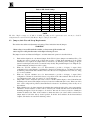
DIP Switches
The DIP switch (see Table 3) on the rear panel should be set when the switcher is operated via the RS-232 or
RS-485/422 connector, or when it is interconnected with other switchers. These switches allow proper
configuration of the control signals received and transmitted through the RS-232 control port. Each of the “ VS”
switchers allows master/slave configurations. This allows the switchers to operate independently, or in
conjunction with each other.
KRAMER ELECTRONICS LTD.
11
Table : DIP Switch Settings
Switcher #
Machine 1 (Master)
Machine 2 (Slave)
Machine 3 (Slave)
Machine 4 (Slave)
Machine 5 (Slave)
Machine 6 (Slave)
Machine 7 (Slave)
Machine 8 (Slave)
1 (Reply)
ON
ON or OFF
ON or OFF
ON or OFF
ON or OFF
ON or OFF
ON or OFF
ON or OFF
DIP Switch #
2
3
ON
ON
ON
ON
ON
OFF
ON
OFF
OFF
ON
OFF
ON
OFF
OFF
OFF
OFF
4
ON
OFF
ON
OFF
ON
OFF
ON
OFF
NOTE
The Slave "Reply" settings are all ON or all OFF, depending on the requirements of the system (see detailed
configuration in section 12.4-12.6). The Master "Reply" setting is always ON.
9.2
Jumpers, their Uses and Set-up Requirements
The switcher has additional adjustments and settings. These include the internal jumpers.
WARNING!
Mains voltage is accessible inside the switcher, so always turn off the switcher and
remove its power cable from the mains socket before removing its cover.
The jumper locations are illustrated in Figure , and their functional operation is described below:
Each switcher input has its own internal jumper. In the VS-1211, these jumpers are numbered J21 to J33
and they are factory located in the position that provides a 75ohm input termination. If the 75ohm
termination is not required, the jumper must be relocated to its alternate position (floating on the pin
remote from the input socket and not connected in any circuit). The particular input is now "High-Z" (not
75ohm terminated) and may be used for looping.
When two VS-1211 switchers are to be interconnected to provide a 12 input, 2 output (12x2)
configuration by looping Input #1 of switcher #1 to Input #1 of switcher #2, etc., J35 must be located in
its alternate position in all of the switchers. This is also the case for configurations 12x3, 12x4, etc., using
3, 4, or more switchers.
When two VS-1211 switchers are to be interconnected to provide a 24 input, 1 output (24x1)
configuration, J35 must be located in its factory set position in all of the switchers. This is also the case
for configurations 36x1, 48x1, etc., using 3, 4, or more switchers.
Jumper J20 is used to define the Sync video source for all the switcher inputs, so that Vertical Interval
Switching can be assured. The jumpers are factory located for an External Sync source. If the sync of the
video source on Input #1 is preferred, then J20 must be relocated to its alternate position in any one of
the switchers.
When switchers are to be interconnected, the switcher that contains the active video sync source must be
identified to all the switchers so that it can be sensed by all of them and thus ensure Vertical Interval
Switching throughout. J34 is the jumper to be used for this task. It is factory located to identify the
switcher in which it sits. Thus, in the switcher to which the active sync source will be connected, the
jumper must be left in the factory located position. In all the other switchers in the interconnected
complex, J34 must be relocated in its alternate position.
KRAMER ELECTRONICS LTD.
12
Figure : Location of Internal Jumpers
KRAMER ELECTRONICS LTD.
13
9.3
The Internal Trimmers
The trimmers are internally located and are accessed through holes in the switcher base (see section 14.2 “ Weak
Switcher Video Signals” ). These allow you, if necessary, to adjust the switcher output signal level and cable
compensation.
10. CONTROLLING THE SWITCHER
The VS-1211/411 and VS-1201xl/401xlm switcher families can be controlled by the following methods:
By touch buttons on the front panel (see section 12.2 "Operating an Individual Switcher").
By direct remote contact closure via the DB-15 socket (a switch panel that the customer rigs up).
By PC or other remote control via the switcher'
s RS-232 or RS-485/422 connector.
There are three different options for the RS-232 or RS-485/422 remote control:
1.
2.
3.
A PC that communicates with the switcher directly.
A Serial remote control unit such as the KRAMER VS-2000 or VS-3000 (see section10.1) or the VS-1N/P
(see section 10.2) combination.
Any RS-232 or RS-485/422 controller, which is programmed according to the protocol of the switcher (see
section 15 “ Protocol Used for VS-1211 Communication").
10.1 The VS-2000 System
The KRAMER VS-2000 is a Programmable Remote Control Unit, designed for use in video production and
duplication studios and in live broadcasting and editing configurations. It provides access to and control of up to
six groups of KRAMER switchers from a single point. A group can comprise several interconnected switchers
which, in turn, permit access to various pieces of equipment (monitors, mixers, editors, VCRs, etc). The VS2000 can be controlled by pressing its front panel touch buttons, or via a PC using the RS-232 control port.
KRAMER PC control software is provided with the BC-2000. Since new switcher types are constantly being
added and older types upgraded, KRAMER provides a small door marked "EPROM" on the VS-2000 rear panel
for easy replacement of the existing chip with an updated chip. This will contain the appropriate information for
the new and modified switchers. KRAMER will make updated chips available periodically. The VS-2000 can
store and recall preferred configurations for convenience in studio control.
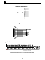
10.2 The VS-1N/VS-1P System
The VS-1N RS-232 Remote Controller interfaces between any KRAMER RS-232 controlled switcher of the
VS-1211/411 series, and a remotely located simple switching assembly. By pressing one of the remote switches,
a connection command is sent to the switcher via the VS-1N and the RS-232 link. The VS-1N permits remote
control of a KRAMER switcher, without interfering with local control by the built-in touch buttons on the
switcher itself, and without using a PC. In fact, the VS-1N is a translator, simulating a computer to the switcher
via its RS-232 port. It accepts mechanical contact switching from the remote point using a KRAMER VS-1P
satellite unit or a switch panel that the customer rigs up himself. The VS-1P is an optional, 24-switch assembly
connected to the VS-1N via a 25 wire flat cable, equipped with the appropriate connectors, and may be
purchased separately as a small single unit. An alternative option is the VS-1P2, a dual VS-1P unit, in a 19-inch
rack configuration. The VS-1N/VS-1P set-up is an ideal remote control for use in video production studios, in
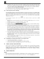
live broadcasting configurations, in CCTV and in security applications. The remote connector socket pinout and
functional description are shown in Figure .
KRAMER ELECTRONICS LTD.
14
Figure : VS-Series Remote Connector Socket and Balanced Audio Pinout
KRAMER ELECTRONICS LTD.
15
11. CONNECTING TO A PC
To connect directly to a PC without using the KRAMER Null-Modem Adapter, make connections as in Figure
1. To use the KRAMER Adapter instead (recommended), plug one end into the PC'
s serial port, then connect
from the other end to the switcher using a 9-pin flat-cable. Alternatively, connect only pins 2, 3, and 5 from the
Adapter to the switcher (one-to-one connection).
11.1 New Protocol 2000
All the switcher described in this manual have built-in a dual communication protocol option. The standard
protocol described in this manual allows simple and fast control of a single switcher or several machines
connected together. The new communication protocol named PROTOCOL 2000, allows the user to control
several different switchers or switchers/matrix groups from one screen. The PC software backing up the new
protocol is called K-ontrol, allowing viewing and monitoring four different machines, which have protocol
2000 built-in from one screen. The new protocol allows more control over the switchers, but is more
complicated than the current protocol supported by the K-Switch software.
The full set of software and documentation is available on the software CD and on Kramer’ s website free for
download. The new software package allows the user to install all versions of software suitable for the machine
used. For the machines described in this manual, both the K-Switch and the K-ontrol software may be installed.
11.1.1
Changing communication protocols
You can work with one of 2 protocols. To work with PROTOCOL 2000, simultaneously press buttons 1 and 4
on the front panel and turn the machine off for at least 5 seconds. When you turn on the machine, it will use
PROTOCOL 2000. Alternatively, you can work with the old protocol. To do so, simultaneously press buttons 1
and 3 on the front panel and turn the machine off for at least 5 seconds. When you turn on the machine, it will
use the old protocol.
11.1.2
Additional software options
The latest version of the K-switch program allows the user to convert any of the switchers described in this
manual to a very sophisticated sequential switcher with no extra cost. The program allows full control on the
switching sequence, dwell time for each input etc. The latest software upgrades are available at Kramer’ s web
site: www.kramerelectronics.com at the technical support section.
12. USING THE SWITCHER
12.1 Powering on the Switcher
The switcher should only be powered on after all connections are completed and all source devices have been
powered on. Do not attempt to connect or disconnect any video, audio or control signals to the switcher while it
is powered on. The switcher may be powered on by pressing the toggle switch on the far-left front panel to the
up position. In the up position, the toggle switch glows, and the active input button illuminates as well.
12.2 Operating an Individual Switcher
NOTE
The operation of all the switchers described in this manual is similar. The VS-1211 operation is described and may
be applied accordingly to the others.
Operation of the VS-1211 switcher units by local control is as follows:
1.
2.
Connect up to twelve video/audio-stereo sources to the input sockets of the switcher.
Connect a video/audio-stereo acceptor to the output socket of the switcher.
KRAMER ELECTRONICS LTD.
16
12.2.1
Selecting an Input on the Switchers
Input selection on the switchers described in this manual is simply made by pressing buttons marked “ 1” , “ 2”
etc. on the front panel, or by operating your preferred remote device (see "KRAMER Switcher Remote Control
Options"). These buttons correspond to the input connections as marked on the back panel.
12.2.2
Selecting the Proper Sync Format
The Sync will be provided from an external video source. If you wish, instead, to use the sync of the video
source connected to Input #1, you must make an internal jumper adjustment as described previously (see section
9.2).
12.2.3
Using the VS-2000
Connect, as required, each of the VS -2000 ports to each of the switcher groups. Perform the preset procedure to
identify the switchers to the VS -2000 before you activate the system. You can control the switcher groups from
the panel touch buttons. You can also control the VS -2000 by a remote computer connected to the "To PC"
connector on the VS -2000. You will see on the screen a complex of switchers covering all the switcher groups
connected to the VS -2000. You can address and control each of them from the PC.
12.3 Using the PC Control Software
The switcher comes with K-Switch control software for Windows 95 and a booklet describing its operation. To
operate interconnected switchers via RS-232 and the KRAMER K-Switch software, perform the following
steps, in order, before connecting the power cables:
1.
2.
3.
4.
5.
6.
7.
8.
Set up the Dipswitch on each switcher in accordance with "Table of DIP Switch Settings" ( Table 3,
Section 9) and mark them accordingly for future reference.
Set up the jumpers as described in "Jumpers, Their Uses and Set-up Requirements" (Section 9.2).
Connect the first switcher to the second switcher via their RS-485 communication ports (connect "A" to
"A", and "B" to "B"). Similarly, continue the connection from the second to the third, and so on.
Connect the first switcher to the PC'
s COM port, via the null-modem adapter provided (see Note below
and Figure 1.
Make sure that the RS-232 cable is not more than 30 feet long.
If several machines are looped, interconnect as described in the relevant section below (12.4, 12.5, 12.6, or
12.7)
Connect the power cable of each switcher to the mains and turn them ON.
Activate the computer and the KRAMER K-Switch software. Then click the mouse button at the
appropriate location on the monitor display to operate all the switchers simultaneously.
NOTE
The KRAMER null-modem adapter is a small plug with two connectors: a DB-9 on one side and a DB-25 or DB-9 on
the other. We provide it with all switchers that have RS-232 ports. It interfaces between the DB-9 connector on the
switcher and the connector on the PC. Its function is to convert the PC output to a null-modem output and permit two
way communication between the switcher and the PC. This is effected by the interconnections within the plug.
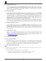
12.4 Adding Outputs
Two VS-1211 switchers may be interconnected to function as a 12x2 switcher by connecting the same
numbered sources to the same numbered inputs of both switchers. However, before doing so, each switcher
input has an internal jumper that must be properly set up to avoid double loading.
Proceed as follows:
1. After disconnecting the switcher from the mains voltage, carefully remove the cover of the first switcher
that is to receive the source signals, remove jumpers J21 to J33 (for VS-1211) and relocate them in their
alternate positions (floating on the pin remote from the input socket and not connected in any circuit).
2. The input impedance of each input is now "High-Z" (not 75ohm terminated) and is therefore suitable for
this application. In the second switcher, the terminating jumpers stay in place, providing 75ohm
terminations. Thus, you do not have to open the second switcher. Carefully close the first switcher.
KRAMER ELECTRONICS LTD.
17
3.
4.
5.
6.
7.
8.
Connect the output from video source #1 to the first switcher input #1, then to the second switcher input #1
using a T or Y connector. Repeat for source #2 and input #2, etc.
Connect one acceptor to the output of one switcher and another acceptor to the output of the other
switcher. You now have a twelve input switcher complex with two outputs.
You can continue to expand the number of outputs by adding a third switcher, etc., to obtain a 12x3
switcher, etc. In such cases, relocate to their alternate position, all input jumpers in all switchers except the
last, so that all the lines are properly terminated by 75ohm. Audio can be connected in a similar manner,
but you do not have to open switchers and remove jumpers, just connect the wires from audio input to
audio input. There is no need for special termination since the input impedance is high.
For RS-232 control of the system, connect the PC to the Master switcher via the null modem adapter.
Each switcher in the configuration should be allocated a unique machine number and the "Reply" option
should be set to ON (see Table 3: DIP Switch Settings). Jumper J35 should be relocated to its alternate
position.
The system may also be controlled via its RS-485 port (see section 12.3 above).
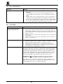
A typical switchers setup where additional outputs are added is described in Figure .
Figure : Connecting Two Switchers for adding More Outputs
12.5 Adding Inputs
Two or more VS-1211 switchers can be interconnected to function as a 24x1 or a 36x1 etc., switcher as follows:
1.
2.
3.
4.
5.
6.
Make sure that jumper J35 in at least one of the switchers is in its factory located position (See Figure ).
If necessary, carefully remove the covers of the switchers to do so.
Connect a straight, 9 wire flat cable from the "To Next" DB-9 connector on the first switcher to the "To
Next" DB-9 connector on the second switcher, from the second to the third and so on, until all the required
switchers are interconnected. Make sure that the interconnecting lengths of cable are as short as possible.
Interconnect the switchers via their RS-485 ports ("A" to "A", "B" to "B", etc.).
Assign a unique machine number to each of the switchers. Set DIP switches as in "Table of DIP Switch
Settings" (see section 9).
On all the units, set the Dipswitch "Reply" option to ON.
In order to feed the sync information from one of the units to all the others, interconnect the units via their
"To Next" connectors using a flat cable. In this case, jumper J34 must be set in its factory located position
in the unit with the Sync source, but in its alternate position in the others.
KRAMER ELECTRONICS LTD.
18
7.
For RS-232 control of the system, connect the PC to the Master switcher via the null modem adapter. Each
switcher in the configuration should be allocated a unique machine number and the "Reply" option should
be to “ ON” (see Table 3, "Table of DIP Switch Settings"). The system may also be controlled via RS-485.
8. Connect the sources to the appropriate switcher inputs.
9. Connect the power cable of each switcher to the mains supply and turn ON each switcher.
10. You now have a 24 or 36, etc. input switcher complex, with one output.
12.6 Video Component and YC Switching
A most important application for interconnected switchers is in professional component video switching, where
smooth switching is required, free from transient effects. Four switchers of the same type are required for RGBS
systems, three for RGB or YUV systems and two for YC systems. The following describes how to set up the
RGB video component application with five professional video sources, each with Red, Green and Blue (RGB)
outputs (Sync on Green).
NOTE
In the following description, "R", "G", "B" refers to three different switchers required for the RGB
implementation.
1.
2.
3.
4.
5.
6.
7.
8.
Interconnect three, same model switchers of the VS-1211 family via their RS-485 ports ("A" to "A", "B" to
"B", etc.).
On all the units except one, set the Dipswitch "Reply" option to OFF.
Set all the switchers to the same Machine number (Dipswitch).
If RS-232 control is required, connect the PC via the null modem adapter to the unit in which the "Reply"
option is set to ON (the system may also be controlled via RS-485).
To synchronize the machines (for vertical interval switching) to input#1 of the G unit, daisy-chain from
G'
s input #1 to the ext. sync input of R and continue to the ext. sync input of B (using "T" connectors).
Place the following jumpers in their alternate positions: J22 and J20 in the G unit and J21 in the R unit.
Also, ensure that the following jumpers are in their factory default positions: J34 in all the units; J20 in the
R and the B units; and J21 in the B unit. To synchronize using an external sync signal, configure R and B
as described above, but this time daisy chaining from G'
s ext. sync. Connect the external sync to G and set
G'
s jumper J20 and J22 to their factory default positions and J21 to its alternate position.
Now connect the R, G and B outputs of camera #1 to input #1 on each of the switchers respectively, those
of camera #2 to input #2 on each of the switchers respectively, and continue until all five camera R, G and
B outputs have been connected to the appropriate switcher inputs, in the same order. Let us call them
switchers R, G and B.
Connect the single outputs of switchers R, G and B to the R, G and B inputs, respectively, of a professional
acceptor, such as a monitor or VCR.
Turn the power ON and select the input number to be switched to the acceptor.
12.7 Controlling Several Independent Switchers Via a Single PC Port
1.
2.
3.
Assign unique machine numbers to each switcher.
Connect via the null modem cable from the PC to the "Master" machine.
Interconnect the switchers via their RS-485 ports ("A" to "A", "B" to "B", etc.).
13. TAKING CARE OF YOUR SWITCHER
Do not locate your switcher in an environment where it is susceptible to dust or moisture. These may damage
the electronics, and cause erratic operation or failure. Do not locate your switcher where temperature and
humidity may be excessive. Do not clean your switcher with abrasives or strong cleaners. Doing so may remove
or damage the finish, or may allow moisture to build up. Take care not to allow dust or particles to build up
inside unused or open connectors.
14. TROUBLESHOOTING
NOTES:
1.
2.
Please note that if the output signal is disturbed or interrupted by very strong external electromagnetic interference, it
should return and stabilize when such interference ends. If not, turn the power switch off and on again to reset the machine.
If the recommended actions still do not result in satisfactory operation, please consult your KRAMER Dealer.
KRAMER ELECTRONICS LTD.
19
14.1 Power and Indicators
Problem
Remedy
1.
No Power
2.
3.
Confirm that the rocker switch is in the “ ON” position, and that the lamp is
illuminated.
Confirm that power connections are secured at the amplifier and at the
receptacle. Make sure the receptacle is active, outputting the proper mains
voltage.
If there is still no power, check the fuse. Remove power cord from the AC
outlet and from the machine and then, using a flat head screwdriver, remove
the fuse holder located directly below the power connector. Confirm that the
fuse is good by looking at the wire connected to the ends of the fuse. If the
wire is broken, replace the fuse with another, with the same value.
14.2 Video Signal
Problem
No video at the output device,
regardless of input selected.
Remedy
1.
2.
3.
Video level is too high or too dim.
1.
2.
Weak switcher input signals
Confirm that your sources and output device are powered on and connected
properly. Video signals connected to the input of your switcher should be of an
identical signal format at the output of your source. Video signals at the output
of your switcher should be of an identical signal format as at the input of your
display or recorder.
Confirm that any other switchers in the signal path have the proper input and/or
output selected.
Use the Video Tester to test the video path leading to/from your switcher (see
section 4.1 " Video Tester")
Verify that the video line is well interfaced through 75ohm impedance,
otherwise it results in a video level that is too high or too dim when looping is
performed and the termination switches are not in proper position.
Confirm that the connecting cables are of high quality, properly built and
terminated with 75ohm BNC connectors. Check level controls located on your
source input device or output display or recorder.
The switcher contains two internal trimmers, accessed via two holes in the base of
the switcher. These allow, if necessary, to adjust switcher output signal level. For
example, if you are using a long cable with heavy losses, you can compensate for it
by fine tuning the signal using the two trimmers. One trimmer adjusts the gain of
the whole video signal and the other adjusts only the high frequencies of the video
which have been degraded by a low quality cable. The hole closer to the power
socket controls the cable compensation the other controls the video level.
WARNING! Do not use the trimmers except in cases where the cable losses
result in poor resolution of detail or when the whole signal level crashes.
Once they have been touched, the accurate signal transparencies that have been
fine-tuned in the factory are lost. To readjust to the original signal status you need
a stable signal generator and a good quality signal analyzer.
KRAMER ELECTRONICS LTD.
20
Problem
Remedy
Noise bars are “ rolling” up or down in the output image
Hum bars (ground loop) are caused by a difference in the
ground potential of any two or more devices connected to
your signal path. This difference is compensated by passing
that voltage difference through any available
interconnection, including your video cables.
or:
Low frequency hum in the output signal
WARNING!
Do not disconnect the
ground from any piece of
video equipment in your
signal path!
Check the following to remove hum bars:
1.
Confirm that all interconnected equipment is connected
to the same phase of power, if possible.
2.
Remove equipment connected to that phase that may
introduce noise, such as motors, generators, etc.
3.
Disconnect all interconnect cables and reconnect them
one at a time until ground loop reappears. Disconnect the
affected cable and replace, or insert an isolation
transformer in the signal path.
14.3 Audio Signal
Problem
No audio at the output device,
regardless of input selected
Remedy
1.
2.
Audio level is too low
1.
2.
Confirm that your sources and output device are powered on and connected
properly. Audio signals connected to the input of your switcher should be properly
wired to the output of your source. Audio signals connected to output of your
switcher should be properly wired to the input of your switcher or recorder.
Confirm that any other switchers in the signal path have the proper input and/or
output selected. Pay special attention to input switchers that may be built into your
switcher or recording device.
Confirm that the connecting cables are of high quality and properly built. Take
special care in noting the wiring configuration of balanced to unbalanced cables.
Check level controls located on your source input device or output display or
recorder.
The switcher switches the
video but does not switch the
audio.
One of the audio cables leading to the main board is disconnected and cannot transfer
the switch command to the video.
The switcher will not switch
via the RS-485 control
The RS-485 control is fed by a flat cable from the upper audio board to a socket on
the main board. One of its connectors may be disconnected.
Turn OFF the mains switch, remove the power cord from the mains socket and
carefully remove the cover of the switcher. Verify that all the flat cables from the
main board to the control board, from the audio board to the main board and from the
switchboard to the main board are undamaged and properly connected.
NOTE
Sometimes connectors work loose and have to be reinserted.
(Perform this firmly but with care).
KRAMER ELECTRONICS LTD.
21
14.4 Software
Problem
Software version is not updated
Remedy
Carefully remove the switcher cover and identify the EPROM chip that is located
in the middle of the main board, marked by a white sticker. Remove the chip
with the proper tools and insert the new EPROM carefully, observing proper
polarity.
14.5 Control
Problem
No control of switcher from VS2000 control panel
Remedy
3.
4.
5.
6.
7.
No control of switcher from PC
software
1.
2.
3.
4.
5.
6.
7.
Confirm that the connecting cable is wired for pins 1-9 straight through.
Confirm that all DIP switches on the switcher have been set properly. Keep in
mind that if you are only controlling one switcher on a specific port, that
switcher must be assigned the ID of “ 1” .
If controlling more than one switcher on a single port, all switchers must be
of the same type and power to all switchers must be on.
Confirm that you have the proper machine number and control port selected
on the VS-2000. For instance, if you are controlling a single machine on port
1, then both of these should be set to “ 1” .
Confirm that you have the proper switcher type selected on the VS-2000. If
not, go back to Section 12.2.3 of this manual “ Using the VS-2000 Remote
Control Panel” .
Confirm the wiring of the connecting cable. This pin configuration may be
found in Section 11 “ Connecting to a PC or Compatible System” . Cable
length should not exceed 25 feet.
Confirm that all DIP switches on the switcher have been set properly. Keep in
mind that if you are only controlling one switcher on a specific port, that
switcher must be assigned the ID of “ 1” .
If controlling more than one switcher on a single port, all switchers must be
of the same type and power to all switchers must be on.
Confirm that the baud rate of your computer COM port is set to the same as
that of your switcher (9600-Baud). Confirm that the proper COM port is
selected in the control software.
Confirm that bi-directional communication is enabled on all switchers. Please
refer to Section 9 “ The Configuration Switches jumpers and trimmers” for
proper configuration for your switcher.
With custom software, do not send multiple commands at the same time. The
switcher must complete one command before receiving another.
Confirm that the computer you are using supports true RS-232C protocol.
Computers, such as the Apple Macintosh do not!
14.6 Switching Malfunctions
Problem
The switcher succeeds in switching
a number of sources then fails to
switch one
Remedy
Malfunction in the particular source or cable assembly.
NOTE: The most common failure mode in transferring the signal of an audio
source is a break in the connecting wire.
Disconnect the source from a channel that is switching successfully and connect
the suspect source to it. If the channel continues to switch successfully, then
there is something wrong with the switcher or the suspect source was not
connected properly. If it does not continue to switch successfully, then there is
something wrong with the source or cable assembly. Check them.
The switcher turns ON but will not
switch at all
KRAMER ELECTRONICS LTD.
One of the two flat cables leading from the main board to the control board may
be disconnected and the switch command is not being transferred to the switcher.
22
14.7 Vertical Interval
Problem
Remedy
The switcher is switching, but there
are transitional effects when using
genlocked sources. The picture
jumps and rolls, and the color is lost
until the acceptor (a VCR, for
example) has readjusted itself to the
new color information.
There is no vertical interval Sync source for switching. It should be available
either on video input #1 or on an external genlocked source as a live video or a
live black burst signal. Which one, will depend on certain jumper settings.
Turn OFF the power switch, remove the power cable from the mains socket and
carefully remove the cover of the switcher. Carefully remove the audio board by
unscrewing the four upper board screws. The upper board can now be raised with
ease. Find jumper J20 (also J34 in an interconnected configuration) and set up
the Sync source in accordance with "Jumpers, Their Uses and Set-up
Requirements" (see section 9.2).
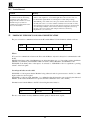
15. PROTOCOL USED FOR VS-1211/1201xl COMMUNICATION
The protocol used for communication between the PC and the Master VS-1211/1201xl is defined as follows:
MSB
N7
LSB
N6
N5
N4
N3
N2
N1
N0
Where:
N7 is used for communication between the Slave and the Master only and is always 0 for communication with
the PC.
N6N5N4 is the binary value of the Machine we are addressing minus one, e.g., if we wish to address the Master
(Machine 1 by definition), then N6N5N4 = 000, if we wish to address Machine 6, then N6N5N4 = 101.
N3N2N1N0 is the binary value of the input to be selected, i.e. N3N2N1N0 = 0111 is equivalent to pressing
switch 7 on the front panel.
Several special codes are also valid:
N3N2N1N0 = 1101 requests that the Machine being addressed sends its present status to the PC, i.e. which
input is selected on its front panel.
N3N2N1N0 = 1110 is an "OK" handshake, i.e. confirmation that the instruction was received by the addressed
Machine. (If the addressed Machine is not present, then this confirmation is not sent to the PC).
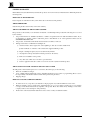
Information sent from the Master to the PC is done using the same format, i.e.:
0
Machine Number -1
New Switch Status
N7
N6N5N4
N3N2N1N0
The rate of data transfer is always 9600 baud, with no parity, 8 data bits and 1 stop bit.
KRAMER ELECTRONICS LTD.
23
LIMITED WARRANTY
Kramer Electronics (hereafter Kramer) warrants this product to be free from defects in material and workmanship under the
following terms.
HOW LONG IS THE WARRANTY
Labor and parts are warranted for three year from the date of the first customer purchase.
WHO IS PROTECTED
Only the first purchase customer may enforce this warranty.
WHAT IS COVERED AND WHAT IS NOT COVERED
Except as below, this warranty covers all defects in material or workmanship in this product. The following are not covered
by the warranty:
1.
2.
3.
Any product which is not distributed by Kramer or which is not purchased from an authorized Kramer dealer. If you
are uncertain as to whether a dealer is authorized, please contact Kramer at one of the agents listed in the web site
www.kramerelectronics.com.
Any product, on which the serial number has been defaced, modified or removed.
Damage, deterioration or malfunction resulting from:
a) Accident, misuse, abuse, neglect, fire, water, lightning or other acts of nature, unauthorized
product modification, or failure to follow instructions supplied with the product.
b) Repair or attempted repair by anyone not authorized by Kramer.
c)
Any shipment of the product (claims must be presented to the carrier).
d) Removal or installation of the product.
e)
Any other cause, which does not relate to a product defect.
f)
Cartons, equipment enclosures, cables or accessories used in conjunction with the product.
WHAT WE WILL PAY FOR AND WHAT WE WILL NOT PAY FOR
We will pay labor and material expenses for covered items. We will not pay for the following:
1.
2.
3.
Removal or installations charges.
Costs of initial technical adjustments (set-up), including adjustment of user controls or programming. These costs are
the responsibility of the Kramer dealer from whom the product was purchased.
Shipping charges.
HOW YOU CAN GET WARRANTY SERVICE
1.
2.
3.
To obtain service on you product, you must take or ship it prepaid to any authorized Kramer service center.
Whenever warranty service is required, the original dated invoice (or a copy) must be presented as proof of warranty
coverage, and should be included in any shipment of the product. Please also include in any mailing a contact name,
company, address, and a description of the problem(s).
For the name of the nearest Kramer authorized service center, consult your authorized dealer.
KRAMER ELECTRONICS LTD.
24
LIMITATION OF IMPLIED WARRANTIES
All implied warranties, including warranties of merchantability and fitness for a particular purpose, are limited in duration
to the length of this warranty.
EXCLUSION OF DAMAGES
Kramer’ s liability for any defective products is limited to the repair or replacement of the product at our option. Kramer
shall not be liable for:
1.
2.
Damage to other property caused by defects in this product, damages based upon inconvenience, loss of use of the
product, loss of time, commercial loss; or:
Any other damages, whether incidental, consequential or otherwise. Some countries may not allow limitations on
how long an implied warranty lasts and/or do not allow the exclusion or limitation of incidental or consequential
damages, so the above limitations and exclusions may not apply to you.
This warranty gives you specific legal rights, and you may also have other rights, which vary from place to place.
NOTE: All products returned to Kramer for service must have prior approval. This may be obtained from your dealer.
NOTICE
This equipment has been tested to determine compliance with the requirements of:
EN-50081:
EN-50082:
CFR-47
"Electromagnetic compatibility (EMC);
generic emission standard.
Part 1: Residential, commercial and light industry"
"Electromagnetic compatibility (EMC) generic immunity standard. Part 1:
Residential, commercial and light industry environment".
FCC Rules and Regulations:
Part 15- “ Radio frequency devices:
Subpart B- Unintentional radiators
CAUTION
Servicing the machines can only be done by an authorized Kramer technician. Any user who makes
changes or modifications to the unit without the expressed approval of the manufacturer will void user
authority to operate the equipment.
Use the supplied power cord to feed power to the machine.
Please use recommended interconnection cables to connect the machine to other components.
KRAMER ELECTRONICS LTD.
25
For the latest information on our products and a list of Kramer
distributors, visit our Web site: www.kramerelectronics.com.
Updates to this user manual may be found at
http://www.kramerelectronics.com/manuals.html.
We welcome your questions, comments and feedback.
Kramer Electronics, Ltd.
Web site: www.kramerelectronics.com
E-mail: [email protected]
P/N: 2900-002002 REV 2