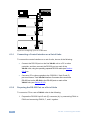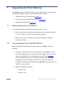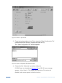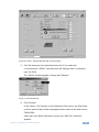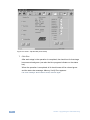
1
K R A ME R E LE CT R O N IC S L T D . USER MANUAL MODEL: VA-8xl 8-Channel Balanced Stereo Audio Amplifier P/N: 2900-300151 Rev 1 Contents 1 Introduction 1 2 2.1 Getting Started Achieving the Best Performance 2 2 3 3.1 Overview Defining the VA-8xl 8-Channel Balanced Stereo Audio Amplifier 3 3 4 Connecting the VA-8xl 6 5 5.1 5.2 Operating the VA-8xl Adjusting the Gain/Attenuation of the Channels Storing and Recalling Setups 8 8 9 6 6.1 6.2 6.3 Controlling the VA-8xl Controlling a Single VA-8xl Unit Preparing the RS-232 Port on a Single Unit Configuring up to a 120 Channel Balanced Stereo Audio Amplifier 11 11 11 13 7 7.1 7.2 7.3 Upgrading the Flash Memory Downloading from the Internet Connecting the PC to the RS-232 Port Upgrading Firmware 18 18 18 19 8 Technical Specifications 24 9 Default Communication Parameters 25 10 10.1 10.2 10.3 Kramer Protocol 2000 Hex Codes for Attenuation Gain Control Hex Codes for Amplification Gain Control Channel Number Codes 26 27 28 28 Figures Figure 1: VA-8xl 8-Channel Balanced Stereo Audio Amplifier Front Panel Figure 2: VA-8xl 8-Channel Balanced Stereo Audio Amplifier Rear Panel Figure 3: Balanced Stereo Audio Connection Figure 4: Unbalanced Stereo Audio Input Connection Figure 5: Unbalanced Stereo Audio Output Connection Figure 6: Connecting the VA-8xl 8-Channel Balanced Stereo Audio Amplifier Figure 7: Crossed Cable RS-232 Connection Figure 8: Straight Cable RS-232 Connection with a Null Modem Adapter Figure 9: Rear Panel DIP-switches (Factory Default) Figure 10: Configuring up to 15 VA-8xl Units Figure 11: Preparing the RS-232 Connectors Figure 12: An RS-485 Control Interface Setup Figure 13: Splash Screen Figure 14: Atmel – Flip Window Figure 15: Open Configuration File Select Window Figure 16: Atmel – Flip Window (RS-232 Communication) Figure 17: RS-232 Window Figure 18: Atmel – Flip Window (Connected) Figure 19: Atmel – Flip Window (Operation Completed) 4 5 6 6 6 7 11 12 12 14 15 17 19 20 20 21 21 22 23 VA-8xl – Contents i 1 Introduction Welcome to Kramer Electronics! Since 1981, Kramer Electronics has been providing a world of unique, creative, and affordable solutions to the vast range of problems that confront the video, audio, presentation, and broadcasting professional on a daily basis. In recent years, we have redesigned and upgraded most of our line, making the best even better! Our 1,000-plus different models now appear in 11 groups that are clearly defined by function: GROUP 1: Distribution Amplifiers; GROUP 2: Switchers and Matrix Switchers; GROUP 3: Control Systems; GROUP 4: Format/Standards Converters; GROUP 5: Range Extenders and Repeaters; GROUP 6: Specialty AV Products; GROUP 7: Scan Converters and Scalers; GROUP 8: Cables and Connectors; GROUP 9: Room Connectivity; GROUP 10: Accessories and Rack Adapters and GROUP 11: Sierra Products. Congratulations on purchasing your Kramer VA-8xl 8-Channel Balanced Stereo Audio Amplifier, which is ideal for the following typical applications: • Large presentation audio level control • Audio broadcast and editing studios • PA remote audio level control VA-8xl - Introduction 1 2 Getting Started We recommend that you: • Unpack the equipment carefully and save the original box and packaging materials for possible future shipment • Review the contents of this user manual Use Kramer high performance high resolution cables Use only the power cord that is supplied with this machine i 2.1 Go to http://www.kramerelectronics.com to check for up-to-date user manuals, application programs, and to check if firmware upgrades are available (where appropriate). Achieving the Best Performance To achieve the best performance: • Use only good quality connection cables to avoid interference, deterioration in signal quality due to poor matching, and elevated noise levels (often associated with low quality cables) • Avoid interference from neighboring electrical appliances that may adversely influence signal quality • Position your Kramer VA-8xl away from moisture, excessive sunlight and dust 2 VA-8xl - Getting Started 3 Overview The VA-8xl 8-Channel Balanced Stereo Audio Amplifier is a high−performance 8-channel, balanced stereo input volume controller for balanced audio signals on terminal block connectors. The volume of each L and R stereo channel can be adjusted independently of the other stereo channel. In particular, the VA-8xl features: • A digitally controlled volume control function, with gain from -95dB (attenuation) up to +31dB (amplification) - in increments of 0.5dB • • Clean, noise-free transition during gain setting changes Transparent performance even in the most critical broadcast applications • • 8 independent channels Control of the amplifier gain of the left and right channels— together or separately—via the front panel buttons, or remotely via RS-232 or RS-485 • Daisy-chaining of up to 15 machines in a single system using RS-485 or RS-232, allowing control of up to 120 stereo audio channels! • Storing and recalling up to 15 configuration setups via the nonvolatile memory, using the front panel buttons, or remotely via RS-232 or RS-485 • A LED display on the front panel, showing the gain of the selected channel (that is, its left and right decibel status) • Easy-to-connect detachable terminal block connectors • A rugged, professional 1U rack mountable enclosure and ship with Windows®-based software 3.1 Defining the VA-8xl 8-Channel Balanced Stereo Audio Amplifier This section defines the VA-8xl. VA-8xl - Overview 3 4 Figure 1: VA-8xl 8-Channel Balanced Stereo Audio Amplifier Front Panel Feature Function 1 POWER Switch Illuminated switch supplying power to the unit 2 CHANNEL SELECTOR Buttons (a). Select/deselect the stereo channel (from 1 to 8) (b). Select a setup number (from 1 to 15) 3 4 5 6 LEVEL Control Buttons # DOWN (a). Decreases the volume in increments of 0.5dB from -95dB to +31dB gain (b). Stores the current setting in the non-volatile memory LEFT Selects/deselects the left channel UP (a). Increases the volume in increments of 0.5dB from -95dB to +31dB gain (b). Recalls a setup from the non-volatile memory RIGHT Selects/deselects the right channel 7 LEFT/dB LED Display Shows the gain of the selected left channel 8 RIGHT/dB LED Display Shows the gain of the selected right channel VA-8xl – Overview 4 VA-8xl - Overview VA-8xl – Overview Figure 2: VA-8xl 8-Channel Balanced Stereo Audio Amplifier Rear Panel # Feature 9 IN Terminal Block Connectors Function Connect to audio sources (from 1 to 8) 10 OUT Terminal Block Connectors Connect to audio acceptors (from 1 to 8) 11 RS-485 Detachable Terminal Block Port Pin # 1 is for Ground; Pin # 2 is for +; Pin # 3 is for – 12 RS-232 9-pin D-sub Port Connects to the PC or the Remote Controller 13 SETUP DIP-switches DIP-switches for setup of the unit 14 Power Connector with FUSE AC connector enabling power supply to the unit 5 VA-8xl - Overview 5 4 Connecting the VA-8xl i Always switch off the power to each device before connecting it to your VA-8xl. After connecting your VA-8xl, connect its power and then switch on the power to each device. To connect the VA-8xl as illustrated in the example in Figure 6: 1. Using the appropriate wiring shown in the figures below, connect up to 8 balanced stereo audio sources (for example, a tape deck) to INPUT CHANNEL 1 – 8 via terminal block connectors: You do not have to connect all channels. 2. Using the appropriate wiring shown in the figures below, connect up to 8 balanced stereo audio acceptors (for example, a stereo amplifier) to OUTPUT CHANNEL 1 – 8 via terminal block connectors: You do not have to connect all channels. 3. If required, connect a PC via RS-232, (see Page 8). Figure 3: Balanced Stereo Audio Connection 6 Figure 4: Unbalanced Stereo Audio Input Connection Figure 5: Unbalanced Stereo Audio Output Connection VA-8xl - Connecting the VA-8xl Figure 6: Connecting the VA-8xl 8-Channel Balanced Stereo Audio Amplifier VA-8xl - Connecting the VA-8xl 7 5 Operating the VA-8xl When switching on the VA-8xl (after a previous session), the VA-8xl briefly scans each channel (stored in the non-volatile memory), showing the settings in the LED displays. After that, the VA-8xl goes to channel 1, and shows its gain/attenuation level in dB. During regular work, the VA-8xl shows the status of the last channel you observed and/or changed. To observe the status of a channel: • Press a CHANNEL SELECTOR button. That CHANNEL SELECTOR button illuminates for about 20 seconds and the decibel values of the selected channel appear in the dimmed LED displays When the LEDs are dimmed, you cannot change the gain or attenuation - the values are for observation only You can control the amplifier gain of the left and right channels via the front panel buttons, or remotely via RS-232 or RS-485. You can increase or decrease the gain in increments of 0.5dB from -95dB up to +31dB. You can control the amplifier gain of the left and/or right channels separately or together (see Section 5.1). 5.1 Adjusting the Gain/Attenuation of the Channels To adjust the amplifier gain or the attenuation: 1. Press the appropriate CHANNEL SELECTOR button. That CHANNEL SELECTOR button illuminates and the decibel values of the selected channel appear in the dimmed LED displays (stored in the non-volatile memory). (When the LEDs are dimmed, you cannot change the gain or attenuation - the values are for observation only). 2. Press the LEFT LEVEL and/or the RIGHT LEVEL button. The decibel values of the selected channel appear in the bright LEFT and/or RIGHT LED display. 8 VA-8xl - Operating the VA-8xl 3. Press the UP or DOWN button once to increase or decrease, as appropriate, in increments of 0.5dB. Press and hold the UP or DOWN button, to increase or decrease the decibel level by a significant amount. 4. Press the LEFT LEVEL or the RIGHT LEVEL button to set the level. The bright LEFT and/or RIGHT LED display becomes dim again, preventing unintentionally altering the settings. 5.2 Storing and Recalling Setups You can store/recall up to 15 settings in the non-volatile memory, via the front panel buttons, or remotely via RS-232 or RS-485. A setting refers to the gain/attenuation level of the selected channel that appears in the dimmed LED displays, and each setting includes all 8 channels. To store a setting, via the front panel buttons: 1. When the LED displays are dimmed, press the DOWN button. The abbreviation “StO” (store) appears in the LEFT LED display. 2. Choose a setup number (between 1 to 8), by pressing the appropriate CHANNEL SELECTOR button. The abbreviation “StO” (store) appears in the LEFT LED display and the setup number appears in the RIGHT LED display. 3. Press the same CHANNEL SELECTOR button again. The memory stores the chosen setup number. As confirmation, for a few seconds, “YES” appears in the LEFT LED display and the setup number appears in the RIGHT LED display. Note: Saving a setup to an previously allocated setup number, overwrites the previous setup To cancel, press the LEFT or RIGHT button VA-8xl - Operating the VA-8xl 9 To recall a setting, via the front panel buttons, do the following: 1. When the LED displays are dimmed, press the UP button. The abbreviation “rCL” (recall) appears in the LEFT LED display. 2. Press the appropriate CHANNEL SELECTOR button. The abbreviation “rCL” (recall) appears in the LEFT LED display and the number of that CHANNEL SELECTOR button appears in the RIGHT LED display. 3. Press the same CHANNEL SELECTOR button again. The memory recalls the setup. As confirmation, for a few seconds, “YES” appears in the LEFT LED display and the setup number appears in the RIGHT LED display. If no setting is stored in the non-volatile memory with that setup #, “NO” appears in the LEFT LED display and the setup number appears in the RIGHT LED display. Note: Recalling a setup implements the amplifier gain or the attenuation immediately 10 VA-8xl - Operating the VA-8xl 6 Controlling the VA-8xl You can control a single VA-8xl unit (see Section 6.1) or configure up to a 120 channel balanced stereo audio amplifier, using 15 units via RS-485 or RS-232 (see Section 6.3). 6.1 Controlling a Single VA-8xl Unit To connect and control a single VA-8xl unit, connect the following to the rear panel: • PC or other controller, see Section 6.2: “Preparing the RS-232 Port on a Single Unit” 6.2 • Set the DIP-switches, see Section 6.2.1 • Power cord Preparing the RS-232 Port on a Single Unit You can connect to the unit via a crossed RS-232 connection, using for example, a PC. A crossed cable or null-modem is required as shown in method A and B respectively. If a shielded cable is used, connect the shield to pin 5. Method A (Figure 7)—Connect the RS-232 9-pin D-sub port on the unit via a crossed cable (only pin 2 to pin 3, pin 3 to pin 2, and pin 5 to pin 5 need be connected) to the RS-232 9-pin D-sub port on the PC. Note: There is no need to connect any other pins. 9 8 7 6 5 4 3 2 1 9 8 7 6 5 4 3 2 PC 1 Figure 7: Crossed Cable RS-232 Connection Hardware flow control is not required for this unit. In the rare case where a controller requires hardware flow control, short pin 1 to 7 and 8, and pin 4 to 6 on the controller side. VA-8xl - Controlling the VA-8xl 11 Method B (Figure 8)—Connect the RS-232 9-pin D-sub port on the unit via a straight (flat) cable to the null-modem adapter, and connect the null-modem adapter to the RS-232 9-pin D-sub port on the PC. The straight cable usually contains all nine wires for a full connection of the D-sub connector. Because the null-modem adapter (which already includes the flow control jumpering described in Method A above) only requires pins 2, 3 and 5 to be connected, you are free to decide whether to connect only these 3 pins or all 9 pins. 9 8 7 6 5 4 3 2 1 Null-Modem Adapter to PC Figure 8: Straight Cable RS-232 Connection with a Null Modem Adapter 6.2.1 DIP-Switch Settings Configure the VA-8xl by setting the DIP-switches as defined in Figure 9: Figure 9: Rear Panel DIP-switches (Factory Default) 6.2.2 DIP # Function: 1-4 Set the MACHINE # (see Section 6.2.2) 5 Not used 6 RS-485 termination for first and last machine = ON (RS-485 line terminates with 110Ω); for others = OFF (RS-485 line is open) 7/8 Used for the firmware upgrade procedure (see Section 7) Setting the MACHINE # To control a unit via RS-232 or RS-485, each unit has to be identified via its unique MACHINE #. Set the MACHINE # on a VA-8xl unit according to the following table. A valid MACHINE # is from 1 to 15. 12 VA-8xl - Controlling the VA-8xl For a single, stand alone machine, set as MACHINE # 1. MACHINE # 6.3 DIP-SWITCH 1 2 3 4 1 ON OFF OFF OFF 2 OFF ON OFF OFF 3 ON ON OFF OFF 4 OFF OFF ON OFF 5 ON OFF ON OFF 6 OFF ON ON OFF 7 ON ON ON OFF 8 OFF OFF OFF ON 9 ON OFF OFF ON 10 OFF ON OFF ON 11 ON ON OFF ON 12 OFF OFF ON ON 13 ON OFF ON ON 14 OFF ON ON ON 15 ON ON ON ON Configuring up to a 120 Channel Balanced Stereo Audio Amplifier To connect up to 15 VA-8xl units, do the following: • Connect the balanced/unbalanced audio sources/acceptors to the rear panel on each unit (see Section 4) • Connect a PC or other controller (see Section 6.3.1) • Set the DIP-switches on each unit (see Section 6.2.1) • Connect the power cord on each unit Figure 10 illustrates how to configure up to 15 VA-8xl units. VA-8xl - Controlling the VA-8xl 13 Figure 10: Configuring up to 15 VA-8xl Units 6.3.1 Connecting a Control Interface on a Set of Units To connect the control interface on a set of units, do one of the following: • Connect the RS-232 port on the first VA-8xl unit to a PC or other controller, and then connect the RS-232 port on each of the VA-8xl units, using the specially prepared RS-232 cable (see Section 6.3.2) or • Connect a PC or other controller to the “RS-232 in” 9-pin D-sub (F) port on a Kramer Tools VP-43xl Interface Converter and connect the RS-485 port on the VP-43xl to the RS-485 ports on each of the VA-8xl units (see Section 6.3.3) 6.3.2 Preparing the RS-232 Port on a Set of Units To connect a PC to a set of VA-8xl units do the following: 1. Prepare the RS-232 9-pin D-sub (F) connector (A), by connecting PIN 4 to PIN 6 and connecting PINS 8, 7, and 1 together. 14 VA-8xl - Controlling the VA-8xl 2. Attach the RS-232 9-pin D-sub (F) connector (A) to another RS-232 9-pin D-sub (M) connector (B) by connecting PIN 5 to PIN 5, PIN 3 to PIN 2, and PIN 2 to PIN 3. 3. Connect the RS-232 9-pin D-sub (F) connector (A) to your PC’s RS-232 9-pin D-sub (M) port. 4. Attach the RS-232 9-pin D-sub (M) connector (B) to another RS-232 9-pin D-sub (M) connector (C), by connecting PIN 5 to PIN 5, PIN 8 to PIN 3, PIN 9 to PIN 2. 5. Connect the RS-232 9-pin D-sub (M) connector (B) to the RS-232 9-pin D-sub (F) port on the first VA-8xl unit. 6. Attach the RS-232 9-pin D-sub (M) connector (C) to another RS-232 9-pin D-sub (M) connector, if required, by connecting PIN 5 to PIN 5, PIN 8 to PIN 3, PIN 9 to PIN 2. 7. Connect the RS-232 9-pin D-sub (M) connector (C) to the RS-232 9-pin D-sub (F) port on the next VA-8xl unit. Figure 11: Preparing the RS-232 Connectors VA-8xl - Controlling the VA-8xl 15 6.3.3 Connecting the RS-485 Control Interface To connect an RS-485 connector on one VA-8xl unit to an RS-485 connector on another unit: 1. Connect the “+” PIN on the first VA-8xl unit to the “+” PIN on the second VA-8xl unit 2. Connect the “-” PIN on the first VA-8xl unit to the “-” PIN on the second VA-8xl unit 3. If shielded cable is used for an RS-485 connection, connect the shield to the Ground PIN. Figure 12 illustrates the RS-485 line that connects: • Between each VA-8xl unit • To the PC via a Kramer Tools VP-43xl Interface Converter (connect the PC’s 9-pin D-sub COM port to the “RS-232 in” 9-pin D-sub (F) port on the VP-43xl. Next, connect the RS-485 port on the VP-43xl to the RS-485 ports on the VA-8xl units) 16 VA-8xl - Controlling the VA-8xl Figure 12: An RS-485 Control Interface Setup VA-8xl - Controlling the VA-8xl 17 7 Upgrading the Flash Memory The VA-8xl firmware is located in FLASH memory, which lets you upgrade to the latest Kramer firmware version in minutes! The process involves: 7.1 • Downloading from the Internet (see Section 7.1) • Connecting the PC to the RS-232 port (see Section 7.2) • Upgrading Firmware (see Section 7.3) Downloading from the Internet You can download the up-to-date file from the Internet. To do so: 1. Go to our Web site at http://www.kramerelectronics.com and download the file: “FLIP_Va8xl.zip” from the Technical Support section. 2. Extract the file: “FLIP_Va8xl.zip” to a folder (for example, C:\Program Files\Kramer Flash). 7.2 Connecting the PC to the RS-232 Port Before installing the latest Kramer firmware version on a VA-8xl unit, do the following: 1. Connect the RS-232 9-pin D-sub rear panel port on the VA-8xl unit to the null modem adapter and connect the null modem adapter with a 9-wire flat cable to the RS-232 9-pin D-sub COM port on your PC (see Section 4). It is recommended that you use COM port 2 (default). However, if your computer has only one COM port, open the file: “Va8xl.cfg” (located at C:\Program Files\Kramer Flash\Va8xl.cfg) in Notepad, and change “set port COM2” to “set port COM1”. 2. Set the DIP-switches as follows: 18 Set DIP 8 ON Set DIP 7 ON VA-8xl - Upgrading the Flash Memory 3. Connect the power cord and turn the POWER switch on the VA-8xl ON. The LED displays may show erratic data, which should be ignored. 7.3 Upgrading Firmware Follow these steps to upgrade the firmware: 1. Double click the desktop icon: “Shortcut to FLIP.EXE”. The Splash screen appears as follows: Figure 13: Splash Screen 2. After a few seconds, the Splash screen is replaced by the “Atmel – Flip” window: VA-8xl - Upgrading the Flash Memory 19 Figure 14: Atmel – Flip Window 3. Press the keyboard shortcut key F4 (or select the “Read Configuration File” command from the File menu, or press the keys: Alt FR). The “Open Configuration File” window appears: Figure 15: Open Configuration File Select Window 4. Choose the file: “Va8xl.cfg” (by double-clicking it). If COM 2 was not selected (see Section 7.2), an RS-232 error message appears. In the “Atmel – Flip” window, the Operations Flow column is disabled, and crosses appear in the third column. 20 VA-8xl - Upgrading the Flash Memory Figure 16: Atmel – Flip Window (RS-232 Communication) 5. Click OK and press the keyboard shortcut key F3 (or select the “Communication / RS232” command from the Settings menu, or press the keys: Alt SCR). The “RS232” window appears. Change the COM port: Figure 17: RS-232 Window 6. Click Connect. In the “Atmel – Flip” window, in the Operations Flow column, the Run button is active, and the name of the chip appears as the name of the third column: T89C51RD2. Verify that in the Buffer Information column, the “HEX File: Va8xl.hex” appears. VA-8xl - Upgrading the Flash Memory 21 Figure 18: Atmel – Flip Window (Connected) 7. Click Run. After each stage in the operation is completed, the check-box for that stage becomes colored green (see also the blue progress indicator on the status bar). When the operation is completed, all 4 check-boxes will be colored green and the status bar message: Memory Verify Pass appears: If an error message: “Not Finished” shows, click Run again. 22 VA-8xl - Upgrading the Flash Memory Figure 19: Atmel – Flip Window (Operation Completed) 8. Close the “Atmel – Flip” window. 9. Turn the POWER switch on the VA-8xl OFF. 10. Disconnect the RS-232 9-pin D-sub rear panel port on the VA-8xl unit from the null modem adapter. 11. Set DIP 7 OFF. 12. Set DIP 8 OFF. 13. Turn the POWER switch on the VA-8xl ON. Upon initialization, the new VA-8xl software version shows in the RIGHT LED display. VA-8xl - Upgrading the Flash Memory 23 8 Technical Specifications INPUTS: 8 balanced stereo audio +4dBm / 30kΩ on detachable terminal blocks OUTPUTS: 8 balanced stereo audio +4dBm / 50Ω on detachable terminal blocks GAIN: -95dB to +31dB MAX. OUTPUT LEVEL: >20dBu balanced (TND +N <0.01) BANDWIDTH (-0.3dB): 20 Hz to 40 kHz NOISE FLOOR: <90dB (GAIN 0dB) THD + NOISE: 0.006%, +4dBu 1kHz CONTROLS: Front pushbuttons, RS-232, and RS-485 INDICATORS: Gain in dB for left and right channels OPERATING TEMPERATURE: 0° to +55°C (32° to 131°F) STORAGE TEMPERATURE: -45° to +72°C (-49° to 162°F) HUMIDITY: 10% to 90%, RHL non-condensing POWER SOURCE: 90 - 240V AC, 13VA DIMENSIONS: 19” x 7” x 1U (W, D, H) rack-mountable WEIGHT: 3.5kg (7.8lbs) approx. ACCESSORIES: Power cord, null modem adapter, Windows®-based control software Specifications are subject to change without notice at http://www.kramerelectronics.com 24 VA-8xl - Technical Specifications 9 Default Communication Parameters RS-232 Protocol 2000 Baud Rate: 9600 Data Bits: 8 Stop Bits: 1 Parity: None Command Format: HEX Example (Output 1 to Input 1): 0x01, 0x81, 0x81, 0x81 Ethernet IP Address: 192.168.1.39 TCP Port Number: 5000 Network Mask: 255.255.255.0 Default Gateway: 192.168.1.1 VA-8xl - Default Communication Parameters 25 10 Kramer Protocol 2000 The VA-8xl is compatible with Kramer’s Protocol 2000 (version 0.50). This RS-232 / RS-485 communication protocol uses four bytes of information as defined below: 1st BYTE: Bit 7 (MSB) Bit 6 Bits 5…0 Defined as 0. 0 - for sending information to the switchers (from the PC) 1 - for sending to the PC (from the switcher). INSTRUCTION The function that the switcher is to perform is defined in the INSTRUCTION table below. Similarly, if a function is performed via the machine’s front panel, then these bits are set according to the INSTRUCTION NO. that was performed. 2nd BYTE: Bit 7 (MSB) Bits 4…0 Bit 5 Bit 6 Defined as 1. Channel number Left (set to 1 when referring to the left channel) Right (set to 1 when referring to the right channel) Note: To mute with regular attenuation use Bit 5 and 6 = 1 To mute immediately use Bit 5 and 6 = 0, however there may be a pop or click on the output of the muted channel. 3rd BYTE: Bit 7 (MSB) Bits 6…0 Defined as 1. 7 least significant bits of data 4th BYTE: Bit 7 (MSB) Bit 5 Bits 4…0 Defined as 1. MSB of data (7 LSBs are in 3rd byte). MACHINE NUMBER. For RS-232, a null-modem connection between the machine and controller is used. For both RS-232/RS-485 interfaces the default data rate is 9600 baud, with no parity, 8 data bits and 1 stop bit. All the values in the table are decimal, unless otherwise stated INSTRUCTION # DESCRIPTION 3rd BYTE 22dec (16hex) SET AUDIO GAIN Set 7 LSBs of gain value Gain (dB) = 31.5 – (0.5x(255-DATA)) 24dec (18hex) INCREASE / DECREASE AUDIO GAIN 0 - increase gain 1 - decrease gain 25dec (19hex) REQUEST AUDIO GAIN As in Instruction 22dec above. When requesting both channels, the reply is: For equal left and right gain: bits 5 = bit 6 For unequal left and right gain: bits 6 = 0; bit 5 = 1 for reply for left channel In addition to the above, instructions 15, 18, 19, 20, 61, 62 (decimal) of Kramer’s Protocol 2000 are also fully implemented in the unit. For instructions 18 and 19, setups 01 to 15 (decimal) are valid. See the following examples: EXAMPLES COMMAND EXAMPLES (MACHINE # 1) 16h E7h 90h 81h Set channel 7 both left and right gain -88dB 16h AAh FFh 81h Set channel 10 left gain -32.5dB 16h CAh COh A1h Set channel 10 right gain 0dB 16h FOh DOh A1h Set channel 16 both left and right gain +8dB 18h EFh 80h 81h Increment (increase) gain on 0.5dB on left and right of channel 15 19h CFh 80h 81h Request gain of channel 15 right. If the gain is 0dB for both left and right channels, then the reply would be: 59h EFh COh A1h 19h EEh 80h 81h Request gain of channel 14 both left and right. If the gain is different for the left and right channels, then, for +3dB gain in the left channel the reply would be: 59h AEh C6h A1h 26 VA-8xl - Kramer Protocol 2000 The following tables define the VA-8xl hex codes for attenuation gain control, amplification gain control and the channel number codes. 10.1 Gain (dB) Mute -95.5 -95 -94.5 -94 -93.5 -93 -92.5 -92 -91.5 -91 -90.5 -90 -89.5 -89 -88.5 -88 -87.5 -87 -86.5 -86 -85.5 -85 -84.5 -84 -83.5 -83 -82.5 -82 -81.5 -81 -80.5 -80 -79.5 -79 -78.5 -78 -77.5 -77 -76.5 -76 -75.5 -75 -74.5 -74 -73.5 -73 -72.5 -72 -71.5 Hex Codes for Attenuation Gain Control LED ---95.5 -95 -94.5 -94 -93.5 -93 -92.5 -92 -91.5 -91 -90.5 -90 -89.5 -89 -88.5 -88 -87.5 -87 -86.5 -86 -85.5 -85 -84.5 -84 -83.5 -83 -82.5 -82 -81.5 -81 -80.5 -80 -79.5 -79 -78.5 -78 -77.5 -77 -76.5 -76 -75.5 -75 -74.5 -74 -73.5 -73 -72.5 -72 -71.5 Hex Codes 16 16 16 16 16 16 16 16 16 16 16 16 16 16 16 16 16 16 16 16 16 16 16 16 16 16 16 16 16 16 16 16 16 16 16 16 16 16 16 16 16 16 16 16 16 16 16 16 16 16 XX XX XX XX XX XX XX XX XX XX XX XX XX XX XX XX XX XX XX XX XX XX XX XX XX XX XX XX XX XX XX XX XX XX XX XX XX XX XX XX XX XX XX XX XX XX XX XX XX XX 80 81 81 81 82 81 83 81 84 81 85 81 86 81 87 81 88 81 89 81 8A 81 8B 81 8C 81 8D 81 8E 81 8F 81 90 81 91 81 92 81 93 81 94 81 95 81 96 81 97 81 98 81 99 81 9A 81 9B 81 9C 81 9D 81 9E 81 9F 81 A0 81 A1 81 A2 81 A3 81 A4 81 A5 81 A6 81 A7 81 A8 81 A9 81 AA 81 AB 81 AC 81 AD 81 AE 81 AF 81 B0 81 B1 81 VA-8xl - Kramer Protocol 2000 Gain (dB) -68 -67.5 -67 -66.5 -66 -65.5 -65 -64.5 -64 -63.5 -63 -62.5 -62 -61.5 -61 -60.5 -60 -59.5 -59 -58.5 -58 -57.5 -57 -56.5 -56 -55.5 -55 -54.5 -54 -53.5 -53 -52.5 -52 -51.5 -51 -50.5 -50 -49.5 -49 -48.5 -48 -47.5 -47 -46.5 -46 -45.5 -45 -44.5 -44 -43.5 LED -68 -67.5 -67 -66.5 -66 -65.5 -65 -64.5 -64 -63.5 -63 -62.5 -62 -61.5 -61 -60.5 -60 -59.5 -59 -58.5 -58 -57.5 -57 -56.5 -56 -55.5 -55 -54.5 -54 -53.5 -53 -52.5 -52 -51.5 -51 -50.5 -50 -49.5 -49 -48.5 -48 -47.5 -47 -46.5 -46 -45.5 -45 -44.5 -44 -43.5 Hex Codes 16 16 16 16 16 16 16 16 16 16 16 16 16 16 16 16 16 16 16 16 16 16 16 16 16 16 16 16 16 16 16 16 16 16 16 16 16 16 16 16 16 16 16 16 16 16 16 16 16 16 XX XX XX XX XX XX XX XX XX XX XX XX XX XX XX XX XX XX XX XX XX XX XX XX XX XX XX XX XX XX XX XX XX XX XX XX XX XX XX XX XX XX XX XX XX XX XX XX XX XX B8 81 B9 81 BA 81 BB 81 BC 81 BD 81 BE 81 BF 81 C0 81 C1 81 C2 81 C3 81 C4 81 C5 81 C6 81 C7 81 C8 81 C9 81 CA 81 CB 81 CC 81 CD 81 CE 81 CF 81 D0 81 D1 81 D2 81 D3 81 D4 81 D5 81 D6 81 D7 81 D8 81 D9 81 DA 81 DB 81 DC 81 DD 81 DE 81 DF 81 E0 81 E1 81 E2 81 E3 81 E4 81 E5 81 E6 81 E7 81 E8 81 E9 81 Gain (dB) -40 -39.5 -39 -38.5 -38 -37.5 -37 -36.5 -36 -35.5 -35 -34.5 -34 -33.5 -33 -32.5 -32 -31.5 -31 -30.5 -30 -29.5 -29 -28.5 -28 -27.5 -27 -26.5 -26 -25.5 -25 -24.5 -24 -23.5 -23 -22.5 -22 -21.5 -21 -20.5 -20 -19.5 -19 -18.5 -18 -17.5 -17 -16.5 -16 15.5 LED -40 -39.5 -39 -38.5 -38 -37.5 -37 -36.5 -36 -35.5 -35 -34.5 -34 -33.5 -33 -32.5 -32 -31.5 -31 -30.5 -30 -29.5 -29 -28.5 -28 -27.5 -27 -26.5 -26 -25.5 -25 -24.5 -24 -23.5 -23 -22.5 -22 -21.5 -21 -20.5 -20 -19.5 -19 -18.5 -18 -17.5 -17 -16.5 -16 -15.5 Hex Codes 16 16 16 16 16 16 16 16 16 16 16 16 16 16 16 16 16 16 16 16 16 16 16 16 16 16 16 16 16 16 16 16 16 16 16 16 16 16 16 16 16 16 16 16 16 16 16 16 16 16 XX XX XX XX XX XX XX XX XX XX XX XX XX XX XX XX XX XX XX XX XX XX XX XX XX XX XX XX XX XX XX XX XX XX XX XX XX XX XX XX XX XX XX XX XX XX XX XX XX XX F0 81 F1 81 F2 81 F3 81 F4 81 F5 81 F6 81 F7 81 F8 81 F9 81 FA 81 FB 81 FC 81 FD 81 FE 81 FF 81 80 A1 81 A1 82 A1 83 A1 84 A1 85 A1 86 A1 87 A1 88 A1 89 A1 8A A1 8B A1 8C A1 8D A1 8E A1 8F A1 90 A1 91 A1 92 A1 93 A1 94 A1 95 A1 96 A1 97 A1 98 A1 99 A1 9A A1 9B A1 9C A1 9D A1 9E A1 9F A1 A0 A1 A1 A1 27 Gain (dB) -71 -70.5 -70 -69.5 -69 -68.5 -12 -11.5 -11 -10.5 -10 -9.5 -9 -8.5 10.2 Gain (dB) Hex Codes -71 -70.5 -70 -69.5 -69 -68.5 -12 -11.5 -11 -10.5 -10 -9.5 -9 -8.5 16 16 16 16 16 16 16 16 16 16 16 16 16 16 B2 81 B3 81 B4 81 B5 81 B6 81 B7 81 A8 A1 A9 A1 AA A1 AB A1 AC A1 AD A1 AE A1 AF A1 LED Hex Codes -43 -42.5 -42 -41.5 -41 -40.5 -8 -7.5 -7 -6.5 -6 -5.5 -5 -4.5 16 16 16 16 16 16 16 16 16 16 16 16 16 16 XX XX XX XX XX XX XX XX XX XX XX XX XX XX Gain (dB) -15 -14.5 -14 -13.5 -13 -12.5 -4 -3.5 -3 -2.5 -2 -1.5 -1 -0.5 EA 81 EB 81 EC 81 ED 81 EE 81 EF 81 B0 A1 B1 A1 B2 A1 B3 A1 B4 A1 B5 A1 B6 A1 B7 A1 LED Hex Codes -15 -14.5 -14 -13.5 -13 -12.5 -4 -3.5 -3 -2.5 -2 -1.5 -1 -0.5 16 16 16 16 16 16 16 16 16 16 16 16 16 16 XX XX XX XX XX XX XX XX XX XX XX XX XX XX A2 A1 A3 A1 A4 A1 A5 A1 A6 A1 A7 A1 B8 A1 B9 A1 BA A1 BB A1 BC A1 BD A1 BE A1 BF A1 Hex Codes for Amplification Gain Control Hex Codes 0 +0.5 +1 +1.5 +2 +2.5 +3 +3.5 +4 +4.5 +5 +5.5 +6 +6.5 +7 +7.5 +8 +8.5 +9 +9.5 +10 +10.5 16 16 16 16 16 16 16 16 16 16 16 16 16 16 16 16 16 16 16 16 16 16 XX XX XX XX XX XX XX XX XX XX XX XX XX XX XX XX XX XX XX XX XX XX Gain (dB) C0 A1 C1 A1 C2 A1 C3 A1 C4 A1 C5 A1 C6 A1 C7 A1 C8 A1 C9 A1 CA A1 CB A1 CC A1 CD A1 CE A1 CF A1 D0 A1 D1 A1 D2 A1 D3 A1 D4 A1 D5 A1 LED +11 +11.5 +12 +12.5 +13 +13.5 +14 +14.5 +15 +15.5 +16 +16.5 +17 +17.5 +18 +18.5 +19 +19.5 +20 +20.5 +21 +21.5 +11 +11.5 +12 +12.5 +13 +13.5 +14 +14.5 +15 +15.5 +16 +16.5 +17 +17.5 +18 +18.5 +19 +19.5 +20 +20.5 +21 +21.5 Hex Codes 16 16 16 16 16 16 16 16 16 16 16 16 16 16 16 16 16 16 16 16 16 16 XX XX XX XX XX XX XX XX XX XX XX XX XX XX XX XX XX XX XX XX XX XX Gain (dB) D6 A1 D7 A1 D8 A1 D9 A1 DA A1 DB A1 DC A1 DD A1 DE A1 DF A1 E0 A1 E1 A1 E2 A1 E3 A1 E4 A1 E5 A1 E6 A1 E7 A1 E8 A1 E9 A1 EA A1 EB A1 LED +22 +22.5 +23 +23.5 +24 +24.5 +25 +25.5 +26 +26.5 +27 +27.5 +28 +28.5 +29 +29.5 +30 +30.5 +31 +31.5 +22 +22.5 +23 +23.5 +24 +24.5 +25 +25.5 +26 +26.5 +27 +27.5 +28 +28.5 +29 +29.5 +30 +30.5 +31 +31.5 Hex Codes 16 16 16 16 16 16 16 16 16 16 16 16 16 16 16 16 16 16 16 16 XX XX XX XX XX XX XX XX XX XX XX XX XX XX XX XX XX XX XX XX EC A1 ED A1 EE A1 EF A1 F0 A1 F1 A1 F2 A1 F3 A1 F4 A1 F5 A1 F6 A1 F7 A1 F8 A1 F9 A1 FA A1 FB A1 FC A1 FD A1 FE A1 FF A1 Channel Number Codes 2B Channel 1 2 3 4 5 6 7 8 28 XX XX XX XX XX XX XX XX XX XX XX XX XX XX Gain (dB) -43 -42.5 -42 -41.5 -41 -40.5 -8 -7.5 -7 -6.5 -6 -5.5 -5 -4.5 21B LED 0 +0.5 +1 +1.5 +2 +2.5 +3 +3.5 +4 +4.5 +5 +5.5 +6 +6.5 +7 +7.5 +8 +8.5 +9 +9.5 +10 +10.5 10.3 LED Left Right A1 A2 A3 A4 A5 A6 A7 A8 C1 C2 C3 C4 C5 C6 C7 C8 Both (L & R) E1 E2 E3 E4 E5 E6 E7 E8 Channel 9 10 11 12 13 14 15 16 Left Right A9 AA AB AC AD AE AF B0 C9 CA CB CC CD CE CF D0 Both (L & R) E9 EA EB EC ED EE EF F0 VA-8xl - Kramer Protocol 2000 VA-8xl - Kramer Protocol 2000 29 ! ! P/N: 2900- 300151 " " Rev: 1