1
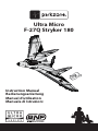
Ultra Micro F-27Q Stryker 180 Instruction Manual Bedienungsanleitung Manuel d’utilisation Manuale di Istruzioni NOTICE All instructions, warranties and other collateral documents are subject to change at the sole discretion of Horizon Hobby, Inc. For up-to-date product literature, visit www.horizonhobby.com and click on the support tab for this product. Meaning of Special Language: The following terms are used throughout the product literature to indicate various levels of potential harm when operating this product: NOTICE: Procedures, which if not properly followed, create a possibility of physical property damage AND little or no possibility of injury. CAUTION: Procedures, which if not properly followed, create the probability of physical property damage AND a possibility of serious injury. WARNING: Procedures, which if not properly followed, create the probability of property damage, collateral damage and serious injury OR create a high probability of superficial injury. WARNING: Read the ENTIRE instruction manual to become familiar with the features of the product before operating. Failure to operate the product correctly can result in damage to the product, personal property and cause serious injury. This is a sophisticated hobby product. It must be operated with caution and common sense and requires some basic mechanical ability. Failure to operate this Product in a safe and responsible manner could result in injury or damage to the product or other property. This product is not intended for use by children without direct adult supervision. Do not attempt disassembly, use with incompatible components or augment product in any way without the approval of Horizon Hobby, Inc. This manual contains instructions for safety, operation and maintenance. It is essential to read and follow all the instructions and warnings in the manual prior to assembly, setup or use in order to operate correctly and avoid damage or serious injury. Age Recommendation: Not for children under 14 years. This is not a toy. 2 EN Thank you for purchasing the ParkZone® Ultra Micro Series F-27Q Stryker 180. You’re just a battery charge away from one of the most exciting ultra micro flying experiences available. The Ultra Micro Series F-27Q Stryker packs the punch of an E-flite® 3000Kv 180 brushless outrunner motor that delivers exhilarating speed and climb performance, just like the big F-27Q. It also has functional twin rudders so you can push the limits with extreme aerobatic maneuvers like flat spins, Snap Rolls, blenders and more. And you get this awesome performance without having to sacrifice any of the smooth, predictable flight characteristics that have made every Stryker a sport pilot favorite. Before you take your first flight, however, you must thoroughly read this manual. The Ultra Micro Series F-27Q is considerably faster than many of the ultra micro aircraft you may be used to flying. Carefully following the setup and binding instructions in this manual will help ensure that first flight, and every one after, is as rewarding (and safe) as it can be. 2S 7.4V 200mAh 25C Lithium Polymer Battery Table of Contents Specifications ..............................................................3 Charging the Battery ................................................4 Battery Warnings .......................................................5 Transmitter and Receiver Binding .......................6 Installing Flight Battery ...........................................6 Before Flight ................................................................6 First Flight Preparation ............................................7 Settings for Control Horns .....................................7 Control Centering .....................................................7 Adjusting Center of Gravity (CG)..........................8 Transmitter and Model Setup ...............................9 Control Direction Test ........................................... 10 Motor Service........................................................... 11 Flying Tips and Repairs ......................................... 12 Additional Safety Precautions and Warnings 13 Maintenance After Flying .................................... 13 Nose Wheel ............................................................... 13 Repairing/Replacing Nose .................................. 13 Replacing Vertical Fins .......................................... 14 Replacing Sub-Fins ................................................ 14 Troubleshooting Guide ........................................ 15 Limited Warranty .................................................... 16 Warranty and Service Information ................... 17 Compliance Information for the European Union ...................................................... 17 Replacement Parts ................................................. 66 Optional Parts and Accessories ........................ 67 Parts Contact Information ................................... 68 Specifications Installed Wingspan 17.0 in (432mm) Length 10.8 in (275mm) 180BL 3,000Kv brushless outrunner Weight 2.15 oz (60 g) (without battery) SpektrumTM AR6400NBL Ultra Micro Receiver/BL ESC unit (4) SPMAS2000L 1.7-Gram Linear Long Throw Servos Included Battery: 200mAh 2S 25C Li-Po Battery Charger: 2S 7.4V Li-Po Needed to Complete Transmitter: 2.4GHz with Spektrum™ DSM2™/DSMX® with adjustable dual rates and expo (DX6i and up) To register your product online, go to www.parkzone.com EN 3 Charging the Battery Your Ultra Micro Stryker comes with a Celectra™ 2S 7.4V DC Li-Po Charger and 2-Cell 7.4V 200mAh 25C Li-Po battery. Please visit www.horizonhobby.com for optional battery adapters. Refer to battery warnings. It is recommended to charge the battery pack while you are inspecting the aircraft. The flight battery will be required to confirm proper aircraft operation in future steps. 2S 7.4V 200mAh 25C Lithium Polymer Battery The Battery Charging Process 1. Charge only batteries that are cool to the touch and are not damaged. Look at the battery to make sure it is not damaged e.g., swollen, bent, broken or punctured. 2. The connector of the battery is specifically designed to only allow it to fit into the charge port one way in order to prevent reverse polarity connection; however, check for proper alignment and polarity before proceeding to the next step. 3. Gently press the battery connector into the charge port located on the front of the charger. 4. When you make the connection successfully, the green LED blinking on the charger will slow, indicating proper connection. 5. Press the button on the charger; the red LED will illuminate, indicating charging has begun. 6. Charging a fully discharged (not over-discharged) 200mAh battery takes approximately 50–60 minutes. 7. When the battery is fully charged, the green LED will illuminate. 8. Always unplug the battery from the charger immediately upon completion of charging. CAUTION: Overcharging a battery can cause a fire. CAUTION: Only use a charger specifically designed to charge a Li-Po battery. Failure to do so could result in fire causing injury or property damage. CAUTION: Never exceed the recommended charge rate. LED Functions under normal operation 1. Green LED blinking with power connected but without battery ................. Standby 2. Green LED blinking ........................................................................................................ Battery is connected 3. Blinking Red LED at varying speeds......................................................................... Charging 4. Red and Green LED blinking simultaneously ....................................................... Balancing 5. Solid Green LED ............................................................................................................... Full Charge 6. Red and Green LED flashing rapidly......................................................................... Error 4 EN Battery Warnings The Battery Charger (EFLCU1007) included with the Ultra Micro Stryker has been designed to safely charge the Li-Po battery. CAUTION: All instructions and warnings must be followed exactly. Mishandling of Li-Po batteries can result in a fire, personal injury and/or property damage. • • • By handling, charging or using the included Li-Po battery, you assume all risks associated with lithium batteries. • If at any time the battery begins to balloon or swell, discontinue use immediately. If charging or discharging, discontinue and disconnect. Continuing to use, charge or discharge a battery that is ballooning or swelling can result in fire. • Always store the battery at room temperature in a dry area for best results. • Always transport or temporarily store the battery in a temperature range of • • • • • 40–120º F. Do not store battery or model in a car or direct sunlight. If stored in a hot car, the battery can be damaged or even catch fire. Always charge batteries away from flammable materials. NEVER USE AN Ni-Cd OR Ni-MH CHARGER. Failure to charge the battery with a compatible charger may cause a fire resulting in personal injury and/or property damage Never discharge Li-Po cells to below 3V under load. Never cover warning labels with hook and loop strips. Never leave charging batteries unattended. Never charge batteries outside safe temperature ranges. Never charge damaged batteries. Low Voltage Cutoff (LVC) When a Li-Po battery is discharged below 3V per cell, it will not hold a charge. The ESC protects the flight battery from over-discharge using Low Voltage Cutoff (LVC). Before the battery charge decreases too much, LVC removes power supplied to the motor. Power to the motor quickly decreases and increases, showing some battery power is reserved for flight control and safe landing. Disconnect and remove the Li-Po battery from the aircraft after use to prevent trickle discharge. Before storage, charge the Li-Po battery to full capacity. During storage, make sure battery charge does not go below 3V per cell. NOTICE: Repeated flying to LVC will damage the battery. When the motor power decreases then increases, please land the aircraft immediately and recharge the flight battery. EN 5 Transmitter and Receiver Binding Binding is the process of programming the receiver of the control unit to recognize the GUID (Globally Unique Identifier) code of a single specific transmitter. You need to ‘bind’ your chosen SpektrumTM DSM2TM/DSMX® technology equipped aircraft transmitter to the receiver for proper operation. For a list of compatible DSM2TM/DSMX® transmitters, please visit www.bindnfly.com. When using a Futaba transmitter with a Spektrum DSM2 module, you will need to reverse the throttle channel. Binding Procedure Reference Table 1. Refer to your transmitter’s unique instructions for binding to a receiver. 2. Make sure the flight battery is disconnected from the airplane. 3. Power off the transmitter. 4. Connect the flight battery in the aircraft. The receiver LED will begin to rapidly flash (typically after 5 seconds). 5. Make sure transmitter controls are neutral and the throttle and throttle trim are in the low position. 6. Put your transmitter into bind mode. Refer to your transmitter’s manual for binding button or switch instructions. 7. After 5 to 10 seconds, the receiver status LED will become solid, indicating that the receiver is bound to the transmitter. If the LED does not go to a solid light, refer to the Troubleshooting Guide at the back of the manual. Installing Flight Battery 1 2 3 Remove canopy from nose of aircraft. Connect fully charged flight battery to receiver. Put battery into battery compartment and install canopy . 2 3 Before Flight 1 Lower throttle and throttle trim to lowest settings. Power on Transmitter Connect flight battery to aircraft. Wait 5 Seconds Series of tones Continuous LED CAUTION: Always keep hands away from propeller. When armed, the motor will turn the propeller in response to any throttle stick. 6 EN First Flight Preparation 7. Perform the Control Direction Test with the transmitter. 8. Adjust flight controls and transmitter. 9. Adjust battery for center of gravity (CG). 10. Perform a radio system Range Check. 11. Find a safe and open area. 12. Plan flight for flying field conditions. 1. Remove and inspect box contents. 2. Read this instruction manual thoroughly. 3. Install Flight battery in the airplane (once it has been fully charged). 4. Bind aircraft to your transmitter. 5. Make sure control rods move freely. 6. Make sure flight control surfaces are centered. Settings for Control Horns Rudder Elevons The illustration shows factory settings for linkages on control horns. After flying, if you want to modify control throw, carefully adjust linkage positions for desired control response. Control Centering Before first flights, or in the event of an accident, make sure the flight control surfaces are centered. Adjust linkages mechanically if control surfaces are not centered. Use of the transmitter trims may not correctly center the aircraft control surfaces due to the mechanical limits of linear servos. 1. Make sure control surfaces are neutral when the transmitter controls and trims are centered. Where possible, transmitter sub-trim must be set to zero. 2. When needed, use a pair of pliers to carefully bend the metal of the linkage (see illustration). 3. Make the U-shape narrower to make the connector shorter. Make the U-shape wider to make the linkage longer. NOTICE: When using a programmable transmitter, do not use sub-trim to adjust the center position of the servo. NOTICE: Ultra micro linear servos are unique in that they are calibrated to reach maximum travel at 100% travel adjust. Increasing the value above 100% will NOT result in more travel, but can cause the servo to lock and will result in a crash. EN 7 Adjusting Center of Gravity (CG) Balance the model on the edge of a metal ruler to find the Center of Gravity. Place the ruler at the bottom side of the fuselage. The recommended CG location is 67mm (2.6 inches) forward from the firewall at the back of the fuselage. This CG location has been determined with the included 2S 200mAh 7.4V Li-Po battery installed approximately in the center of the battery cavity. The battery cavity is oversized to allow for Center of Gravity adjustment. Start by placing the battery in the center of the cavity and adjust as necessary. 67mm 8 EN Transmitter and Model Setup Transmitter Setup Flying wings are controlled by elevons (moveable surfaces on the wing). Elevons take the aileron control (move opposite directions), and elevator control (move up/down same direction) and mixes them together electronically through the transmitter. Make sure both elevons move up and down (travel) the same amount. This model tracks well when the left and right elevon travel the same amount in response to the control stick. Set trims and sub-trims to zero, center control surfaces using pliers if needed, then adjust servo travel so both control surfaces travel the same amount up and down. DX4e and DX5e transmitters Due to the speed and nature of the Ultra Micro Stryker, we recommend using a DSM2™/ DSMX® transmitter with adjustable dual rates, exponential and travel adjust. Without these capabilities, DX4e and DX5e transmitters will operate this model with some flying limitations. We recommend setting all channels at Normal in servo reversing when using DX7, DX8, JR® 9303/9503, 11X and 12X transmitters. For the DX6i, we recommend this setup for servo channel reversing: Throttle: Normal Aileron: Reverse Elevator: Normal Rudder: Normal Receiver elevons connection for DX6i When using the DX6i transmitter, it is necessary to access the AR6400NBL receiver and exchange the aileron and elevator connections where they plug into the receiver “as shown below” in order to achieve the correct control direction. When complete, replace and tape the hatch and do a control test to confirm that the model operates correctly. NOTICE: When using a DSMX non-computer transmitter (DX4e/DX5e) with multiple aircraft, always re-bind and set a model’s failsafe before each flight. Please refer to your transmitter’s manual for failsafe instructions. Model Setup • For the first flight, fly the model in low rate. The first time you use high rate, fly at low to medium speed. High rate, as listed, is only for EXTREME maneuvering. • Use a ruler and measure the surface’s travel at the root of each control surface. Recommended Computerized Transmitter Dual Rates and Expo High Rate Elevator 10–12mm up/down Aileron 10–12mm up/down Rudder Max Travel EN Low Rate 5mm up/down 6mm up/down Max Travel Expo High–50% Low–20% High–40% Low–30% 5% 9 Control Direction Test Bind your aircraft and transmitter before doing these tests (see Binding). Move the controls on the transmitter to make sure aircraft control surfaces move correctly (Mode 2 shown). After doing the Control Test, correctly set the failsafe. Make sure the transmitter controls are neutral and the throttle and throttle trim are in the low position, then rebind the model to your transmitter. If the receiver loses link to the transmitter, failsafe makes the controls and throttle go to these settings made at binding. Up Elevator Down Elevator Left Aileron Right Aileron Left Rudder Right Rudder 10 EN Motor Service CAUTION: Always keep hands away from the propeller, ESC and motor while the flight battery is connected. Failure to do so could result in personal injury. Diassembly A 1. Remove front canopy (A) from the fuselage. 2. Disconnect battery from ESC. 3. Remove battery from hook and loop strips in fuselage. 4. Cut tape on one side of fuselage for the rear hatch. Move the rear hatch, using the remaining tape as a hinge. 5. Disconnect motor connector from ESC/ receiver connector. 6. Remove screw (B) and propeller (C) from motor shaft (D). C 7. Remove 4 screws (F) from motor mount (E) and firewall of fuselage. B D 8. Remove the screw (G) and motor from the motor mount. E F Assembly 1. Assemble model by following instructions above in reverse. 2. Make sure propeller size numbers (3.75 x 3) face the motor (see illustration). G 3. Use a small amount of clear tape to hold the motor wires on the fuselage. Make sure the wires are securely in place when the rear hatch is installed on the fuselage. 75 x3 3. 5x 3 3.7 EN 11 Flying Tips and Repairs For your first flights, set your transmitter timer to 5 minutes. Adjust your timer for longer or shorter flights once you have flown the model. Range Check your Radio System After final assembly, range check the radio system with the Ultra Micro Stryker. Refer to your specific transmitter instruction manual for range test information. Over Current Protection (OCP) CAUTION: Keep hands away from the propeller. Always assume the motor is powered on and that the propeller blades may turn at any time. Launching Always inspect and repair model before flying. Any damage or loose linkages may decrease control in high-speed flight. The UM F-27Q Stryker is equipped with Over Current Protection (OCP). This feature protects the ESC from overheating. OCP stops the motor when the transmitter throttle is set high and the propeller cannot turn. The OCP will only activate when throttle is positioned just above 1/2 throttle. After the ESC stops the motor, fully lower the throttle to re-arm the ESC. CAUTION: Always launch the model with the throttle set at 0% to avoid injury from the propeller. When the model is safely free of your hand, increase throttle to between 60 and 100%. Landing Always launch your model at a very small upward angle and directly into the wind, even in a light breeze. The model’s nose wheel and bottom fin skids let the model land on hard surfaces when needed (which may damage the propeller). Align model directly into the wind and fly down to the ground using 1/4 to 1/3 throttle to keep enough energy for a proper flare. Before the model touches down, always fully decrease throttle to avoid damage to propeller, motor, ESC or other components. Land the model when you notice a reduction in power. If using a transmitter with a timer, set the timer so you have enough flight time to make several landing approaches. When launching your model for the first time, set the dual rate in your transmitter to the low rate position. Hand Launching To hand launch the Ultra Micro Stryker, hold the airplane in the finger grips on the underside of the airplane. Give a firm throw directly into the wind slightly up (5–10 degrees above the horizon) with the throttle all the way down and the propeller not spinning. After release, when the propeller is clear of your hands, add throttle to climb. Flying Only fly your Ultra Micro Stryker in light winds. Always choose a wide-open space for flying your Ultra Micro Stryker. Always avoid flying near houses, trees, wires and buildings. You should also be careful to avoid flying in areas where there are many people, such as busy parks, schoolyards, or soccer fields. Consult local laws and ordinances before choosing a location to fly your aircraft. Failure to lower the throttle stick and throttle trim to the lowest possible positions during a crash could result in damage to the ESC in the receiver unit. NOTICE: Crash damage is not covered under warranty. Always decrease throttle at propeller strike. Repairs Repair the Ultra Micro Stryker using foamcompatible CA (cyanocrylate adhesive) glue or clear tape. Only use foam-compatible CA, as other types of glue can damage the foam. When parts are not repairable, see the Replacement Parts List. For a listing of all replacement and optional parts, refer to the list at the back of this manual. NOTICE: Use of foam-compatible CA accelerant on your model can damage paint. DO NOT handle model until accelerant fully dries. 12 EN Additional Safety Precautions and Warnings • Always carefully follow the directions and warnings for this and any optional support equipment (chargers, rechargeable battery packs, etc.). • Always keep all chemicals, small parts and anything electrical out of the reach of children. • Always avoid water exposure to all equipment not specifically designed and protected for this purpose. Moisture causes damage to electronics. • Never place any portion of the model in your mouth as it could cause serious injury or even death. • Never operate your model with low transmitter batteries. As the user of this product, you are solely responsible for operating in a manner that does not endanger yourself and others, or result in damage to the product or the property of others. This model is controlled by a radio signal subject to interference from many sources outside your control. This interference can cause momentary loss of control, so it is advisable to always keep a safe distance in all directions around your model. This margin will help avoid collisions or injury. • Always keep a safe distance in all directions around your model to avoid collisions or injury. • Always operate your model in open spaces away from full-size vehicles, traffic and people. Maintenance After Flying 1. Disconnect flight battery from the Receiver/ ESC (Required for Safety). 2. Power off transmitter. 3. Remove flight battery from aircraft. 4. Recharge flight battery. 5. Repair or replace all loose or damaged parts. 6. Store flight battery apart from aircraft and monitor the battery charge. 7. Make note of flight conditions and flight plan results, planning for future flights. Nose Wheel 1. Remove and retain screw (A) from nose wheel pant (B) and nose wheel (C). A 2. Remove wheel from nose wheel pant. B C 3. Install wheel and screw in nose wheel pant. Repairing/Replacing Nose NOTICE: Always repair or replace the nose when it is damaged to keep the model flying correctly. 1. When damaged, pull soft nose cone from glue and pin on front of fuselage. 2. Install nose cone on front of fuselage using a small amount of foam-compatible CA. EN 13 Replacing Vertical Fins A B 1. When a vertical fin or rudder is damaged beyond repair using foam-compatible CA, disconnect linkage from control horn. 2. Carefully cut vertical fin from housing in fuselage. 3. Clean glue from fuselage housing. 4. Attach new vertical fin and rudder (A) in fuselage housing (B) using foamcompatible CA (C). 5. Attach linkage to rudder’s control horn. C Replacing Sub-Fins D E 1. When a sub-fin is damaged beyond repair using foam-compatible CA, carefully cut sub-fin from housing in fuselage. F 2. Clean glue from fuselage housing. 3. Attach a new sub-fin (D) in fuselage housing (E) using foam-compatible CA (F). 14 EN Troubleshooting Guide Problem Aircraft will not respond to throttle but responds to other controls Possible Cause Solution Throttle stick and/or throttle trim is too high Reset controls with throttle stick and throttle trim at lowest setting Throttle channel is reversed Reverse throttle channel on transmitter Motor is unplugged from receiver Open fuselage and ensure the plug for the motor is properly installed Extra propeller noise or extra vibration Damaged propeller, prop shaft or motor Replace damaged parts Screw on prop shaft is too loose Tighten the prop shaft screw 1/2 turn Reduced flight time or aircraft underpowered Flight battery charge is low Completely recharge flight battery Propeller is installed backwards Install propeller with numbers facing forward Flight battery is damaged Replace flight battery and follow flight battery instructions Flight conditions may be too cold Make sure battery is warm before use Battery capacity is too low for flight conditions Replace battery or use a larger capacity battery Transmitter is too near aircraft during binding LED on receiver flashes rapidly and aircraft will not process bind to transmitter (during binding) Bind switch or button was not held while transmitter was powered on LED on receiver flashes rapidly and aircraft will not respond to transmitter (after binding) Control surface does not move Power off transmitter, move transmitter a larger distance from aircraft, disconnect and reconnect flight battery to aircraft and follow binding instructions Power off transmitter and repeat bind process Less than a 5-second wait between first powering on transmitter and connecting flight battery to aircraft Leaving transmitter on, disconnect and reconnect flight battery to aircraft Aircraft is bound to a different model memory (ModelMatchTM radios only) Select correct model memory on transmitter and disconnect and reconnect flight battery to aircraft Flight battery/transmitter battery charge is too low Replace/recharge batteries Control surface, control horn, linkage or servo damage Replace or repair damaged parts and adjust controls Wire damaged or connections loose Do a check of wires and connections; connect or replace as needed Flight battery charge is low Fully recharge flight battery Control linkage does not move freely Make sure control linkage moves freely Controls reversed Transmitter settings reversed Do the Control Direction Test and adjust controls on transmitter appropriately (See Transmitter and Model Setup page). Only one elevon responds to controls Transmitter’s elevon function not activated Activate elevon function on transmitter. In some transmitters, this function is also known as Delta Wing. Motor loses power Damage to motor or power components Do a check of motor and power components for damage (replace as needed) Motor power quickly decreases and increases then motor loses power Battery power is down to the point of receiver/ ESC Low Voltage Cutoff (LVC) Recharge flight battery or replace battery that is no longer performing Servo locks or freezes at full travel Travel adjust value is set above 100% overdriving the servo Set Travel adjust to 100% or less and/or set sub trims to Zero and adjust linkages mechanically. EN 15 Limited Warranty What this Warranty Covers Horizon Hobby, Inc. (“Horizon”) warrants to the original purchaser that the product purchased (the “Product”) will be free from defects in materials and workmanship at the date of purchase. What is Not Covered This warranty is not transferable and does not cover (i) cosmetic damage, (ii) damage due to acts of God, accident, misuse, abuse, negligence, commercial use, or due to improper use, installation, operation or maintenance, (iii) modifi cation of or to any part of the Product, (iv) attempted service by anyone other than a Horizon Hobby authorized service center, or (v) Products not purchased from an authorized Horizon dealer. OTHER THAN THE EXPRESS WARRANTY ABOVE, HORIZON MAKES NO OTHER WARRANTY OR REPRESENTATION, AND HEREBY DISCLAIMS ANY AND ALL IMPLIED WARRANTIES, INCLUDING, WITHOUT LIMITATION, THE IMPLIED WARRANTIES OF NON-INFRINGEMENT, MERCHANTABILITY AND FITNESS FOR A PARTICULAR PURPOSE. THE PURCHASER ACKNOWLEDGES THAT THEY ALONE HAVE DETERMINED THAT THE PRODUCT WILL SUITABLY MEET THE REQUIREMENTS OF THE PURCHASER’S INTENDED USE. Purchaser’s Remedy Horizon’s sole obligation and purchaser’s sole and exclusive remedy shall be that Horizon will, at its option, either (i) service, or (ii) replace, any Product determined by Horizon to be defective. Horizon reserves the right to inspect any and all Product(s) involved in a warranty claim. Service or replacement decisions are at the sole discretion of Horizon. Proof of purchase is required for all warranty claims. SERVICE OR REPLACEMENT AS PROVIDED UNDER THIS WARRANTY IS THE PURCHASER’S SOLE AND EXCLUSIVE REMEDY. Limitation of Liability HORIZON SHALL NOT BE LIABLE FOR SPECIAL, INDIRECT, INCIDENTAL OR CONSEQUENTIAL DAMAGES, LOSS OF PROFITS OR PRODUCTION OR COMMERCIAL LOSS IN ANY WAY, REGARDLESS OF WHETHER SUCH CLAIM IS BASED IN CONTRACT, WARRANTY, TORT, NEGLIGENCE, STRICT LIABILITY OR ANY OTHER THEORY OF LIABILITY, EVEN IF HORIZON HAS BEEN ADVISED OF THE POSSIBILITY OF SUCH DAMAGES. Further, in no event shall the liability of Horizon exceed the individual price of the Product on which liability is asserted. As Horizon has no control over use, setup, fi nal assembly, modifi cation or misuse, no liability shall be assumed nor accepted for any resulting damage or injury. By the act of use, setup or assembly, the user accepts all resulting liability. If you as the purchaser or user are not prepared to accept the liability associated with the use of the Product, purchaser is advised to return the Product immediately in new and unused condition to the place of purchase. Law These terms are governed by Illinois law (without regard to confl ict of law principals). This warranty gives you specifi c legal rights, and you may also have other rights which vary from state to state. Horizon reserves the right to change or modify this warranty at any time without notice. 16 Warranty Services Questions, Assistance, and Services Your local hobby store and/or place of purchase cannot provide mwarranty support or service. Once assembly, setup or use of the Product has been started, you must contact your local distributor or Horizon directly. This will enable Horizon to better answer your questions and service you in the event that you may need any assistance. For questions or assistance, please direct your email to productsupport@ horizonhobby.com, or call 877.504.0233 toll free to speak to a Product Support representative. You may also find information on our website at www.horizonhobby.com. Inspection or Services If this Product needs to be inspected or serviced, please use the Horizon Online Service Request submission process found on our website or call Horizon to obtain a Return Merchandise Authorization (RMA) number. Pack the Product securely using a shipping carton. Please note that original boxes may be included, but are not designed to withstand the rigors of shipping without additional protection. Ship via a carrier that provides tracking and insurance for lost or damaged parcels, as Horizon is not responsible for merchandise until it arrives and is accepted at our facility. An Online Service Request is available at www.horizonhobby.com under the Support tab. If you do not have internet access, please contact Horizon Product Support to obtain a RMA number along with instructions for submitting your product for service. When calling Horizon, you will be asked to provide your complete name, street address, email address and phone number where you can be reached during business hours. When sending product into Horizon, please include your RMA number, a list of the included items, and a brief summary of the problem. A copy of your original sales receipt must be included for warranty consideration. Be sure your name, address, and RMA number are clearly written on the outside of the shipping carton. Notice: Do not ship LiPo batteries to Horizon. If you have any issue with a LiPo battery, please contact the appropriate Horizon Product Support office. Warranty Requirements For Warranty consideration, you must include your original sales receipt verifying the proof-of-purchase date. Provided warranty conditions have been met, your Product will be serviced or replaced free of charge. Service or replacement decisions are at the sole discretion of Horizon. Non-Warranty Service Should your service not be covered by warranty service will be completed and payment will be required without notifi cation or estimate of the expense unless the expense exceeds 50% of the retail purchase cost. By submitting the item for service you are agreeing to payment of the service without notifi cation. Service estimates are available upon request. You must include this request with your item submitted for service. Non-warranty service estimates will be billed a minimum of ½ hour of labor. In addition you will be billed for return freight. Horizon accepts money orders and cashiers checks, as well as Visa, MasterCard, American Express, and Discover cards. By submitting any item to Horizon for service, you are agreeing to Horizon’s Terms and Conditions found on our website www.horizonhobby.com/Service/ Request/. EN Warranty and Service Information Country of Purchase Horizon Hobby Address Phone Number/Email Address Horizon Service Center (Electronics and engines) 4105 Fieldstone Rd Champaign, Illinois 61822 USA 877-504-0233 Online Repair Request visit: www.horizonhobby.com/service Horizon Product Support (All other products) 4105 Fieldstone Rd Champaign, Illinois 61822 USA 877-504-0233 [email protected] United Kingdom Horizon Hobby Limited Units 1-4 Ployters Rd Staple Tye Harlow, Essex CM18 7NS, United Kingdom +44 (0) 1279 641 097 [email protected] Germany Horizon Technischer Service Hamburger Str. 10 25335 Elmshorn, Germany +49 4121 46199 66 [email protected] France Horizon Hobby SAS 14 Rue Gustave Eiffel (0) 1 60 47 44 70 Zone d’Activité du Réveil Matin +33 [email protected] 91230 Montgeron United States of America Compliance Information for the European Union Declaration of Conformity (in accordance with ISO/IEC 17050-1) No. HH2011052801 Product(s): Item Number(s): Equipment class: PKZ Ultra Micro F-27Q 180 BNF PKZU2280 1 The object of declaration described above is in conformity with the requirements of the specifications listed below, following the provisions of the European R&TTE directive 1999/5/EC and EMC Directive 2004/108/EC EN 301 489-1 V1.7.1: 2006 EN 301 489-17 V1.3.2: 2008 EN55022: 2006, EN55024: 1998+A1: 2001+A2: 2003 Signed for and on behalf of: Horizon Hobby, Inc. Champaign, IL USA May 28, 2011 Steven A. Hall Vice President International Operations and Risk Management Horizon Hobby, Inc. Instructions for disposal of WEEE by users in the European Union This product must not be disposed of with other waste. Instead, it is the user’s responsibility to dispose of their waste equipment by handing it over to a designated collections point for the recycling of waste electrical and electronic equipment. The separate collection and recycling of your waste equipment at the time of disposal will help to conserve natural resources and ensure that it is recycled in a manner that protects human health and the environment. For more information about where you can drop off your waste equipment for recycling, please contact your local city office, your household waste disposal service or where you purchased the product. EN 17 Replacement Parts • Ersatzteile • Pièces de rechange • Pezzi di ricambio Part # | Nummer Description Numéro | Codice Beschreibung Description Descrizione PKZU2203 Decal Set: UM F-27Q Stryker Dekorbogen Set: UM F-27-Q Stryker UM F-27Q Stryker : Planche de déco Set adesivi: UM F-27Q Stryker PKZU2206 Gear with Wheel: UM F-27Q Stryker Fahrwerk mit Rad: UM F-27Q Stryker UM F-27Q Stryker : Train avec roues Carrello con ruota: UM F-27Q Stryker PKZU2220 Wing/Fuse w/Nose: UM F27Q Stryker Tragfl./ Rumpf m. Nase: mUMF27-Q Stryker UM F-27Q Stryker : Aile, fuselage et nez Ala/Fusoliera con ogiva: UM F27Q Stryker PKZU2222 Pushrod Set: UM F-27Q Stryker Gestänge Set: UM F-27Q UM F-27Q Stryker : Stryker Set de tringleries PKZU2225 Vertical Fin Right: UM Vertikal Finne Rechts: F-27Q Stryker UM F-27Q Stryker UM F-27Q Stryker : Dérive droite Impennaggio verticale destro: UM F-27Q Stryker PKZU2226 Vertical Fin left: UM F-27Q Stryker Vertikal Finne Links: UM F-27Q Stryker UM F-27Q Stryker : Dérive gauche Impennaggio verticale sinistro: UM F-27Q Stryker PKZU2227 Rear Hatch: UM F27Q Stryker Rumpfabdeckung hinten: UM F-27Q Stryker : UM F-27Q Stryker Capot arrière Copertura posteriore: UM F-27Q Stryker PKZU2228 Canopy: UM F-27Q Stryker Kabinenhaube: UM F-27Q Stryker UM F-27Q Stryker : Verrière Capottina: UM F-27Q Stryker PKZU2229 Bottom Fin Set: UM F-27Q Stryker Untere Finnen Set: UM F-27Q Stryker UM F-27Q Stryker : Set de dérives inférieures Set impennaggi inferiori: UM F-27Q Stryker PKZU2230 Control Horn Set: UM Ruderhorn Set: UM FF-27Q Stryker 27Q Stryker UM F-27Q Stryker : Palonniers Set squadrette: UM F-27Q Stryker PKZU2231 Wheel with Bolt: UM F-27 Stryker Rad mit Schraube: UM F-27 Stryker UM F-27Q Stryker : Roue avec écrou Ruota con perno: UM F-27 Stryker PKZU2252 Rubber Nose: UM F-27Q Stryker Gummi Nase: UM F-27Q Stryker UM F-27Q Stryker : Nez en caoutchouc Ogiva in gomma: UM F-27Q Stryker PKZU2253 Servo Cover Set: UM F-27 Stryker Servo Abdeckung Set: UM F-27 Stryker UM F-27Q Stryker : Set copertura servo: UM Set de caches servos F-27 Stryker PKZU2267 Motor Mount: UM F-27Q Stryker Motorträger: UM F-27Q Stryker UM F-27Q Stryker : Support moteur Supporto motore: UM F-27Q Stryker EFLUM180BLB BL180 Brushless Outrunner Motor, 3000Kv BL180 Brushless Außenläufer Motor, 3000 Kv Moteur brushless à cage tournante BL180 3000Kv BL180 Brushless Motore a cassa rotante, 3000Kv EFLUP037503 3.75 x 3 Propeller: UM 3.75x3 Propeller: UM F-27Q Stryker F-27Q Stryker UM F-27Q Stryker : Hélice 3.75x3 3.75 x 3 Elica: UM F-27Q Stryker EFLB2002S25 200mAh 2S 7.4V 25C Li-Po, 26AWG 200mAh 2S 7.4V 25C Li-Po Akku , 26AWG Batterie Li-Po 7.4V 2S 200mA 25C 200mAh 2S 7.4V 25C Li-Po, 26AWG EFLUC1007 Celectra 2S 7.4V DC Li-Po Charger Celectra 2S 7.4V DC LiPo Ladegerät Chargeur Celectra Li-Po 2S Celectra 2S 7.4V DC Li-Po Caricabatterie EFLUC1008 DC Power Cord: UMX Beast DC Ladekabel UMX Beast Alimentation DC DC Cavo alimentazione: UMX Beast EFLH1067 Sicherung Servo:BMCX/ Servo Retaining Collars: BMCX/2/MSR, MSR FHX, MH-35 BMCX/2/ MSR, FHX, MH-35 : Clips d’axe de servo Collari fissaggio servi: BMCX/2/MSR, FHX, MH-35 EFLU4067 Prop Adaptor: UMX Beast E-flite UMX Beast Luftschraubenmitnehmer UMX Beast -Adapta- Adattatore elica: UMX teur d’hélic Beast SPM6832 Replacement Servo Mechanics: Ultra Micro Long Throw Austausch Servo Mechanik:Ultra Micro Long Throw Mécanique d’ultra micro servo longue course Meccanica ricambio servo: Ultra Micro Long Throw SPMAR6400NBL AR6400NBL DSM 6-Channel/Receiver AR6400NBL DSM 6-Kanal / Empfänger AR6400NBL DSM récepteur 6 voies AR6400NBL DSM 6-canali/Ricevitore SPMAS2000L 1.7-Gram Linear Long Spektrum 1.5g Linear Throw Servo Servo, Weg lang Servo linéaire longue course, 1.7g Servo lineare a corsa lunga - 1,7 g 66 Set rinvii: UM F-27Q Stryker Optional Parts and Accessories • Optionale Bauteile und Zubehör • Pièces et accessoires optionnels • Componenti e accessori opzionali Part # | Nummer Description Numéro | Codice Beschreibung Description Descrizione PKZ1039 Hook and Loop Set (5): Ultra Micros Parkzone Klettband (5): Ultra Micros Ultra micro -Set de bande auto-agrippante (5) Set fascette (5): Ultra Micros EFLA700UM Charger Plug Adapter: EFL Ladekabel Adapter EFL Prise d’adaptateur de chargeur EFL Adattatore connettore caricabatterie: EFL EFLA7001UM Charger Plug Adapter: TP Ladekabel Adapter EFL Prise d’adaptateur de chargeur TP Adattatore connettore caricabatterie: TP EFLU4068 Harness Adapter: UMX Beast E-flite UMX Beast Y-Kabel UMX Beast -adaptateur de câbles Adattatore cavi: UMX Beast EFLUB1802S20 180 mAh 2s 7.4V 20C Li-Po, 26AWG 180 mAh 2s 7.4V 20C Li-Po, 26AWG Batterie Li-Po 7.4V 2S 180mA 20C 180 mAh 2s 7.4V 20C Li-Po, 26AWG SPM6825 AS2000 Servo Reverser AS2000 Servokabeladapter Inverseur de servo AS2000 AS2000 Inversore per servo ELFC4000 AC to 12V DC, 1.5Amp Power Supply (US) AC to 12V DC, 1.5Amp Power Supply (US) Adaptateur secteur vers 12V DC, 1.5A (US) AC to 12V DC, 1.5- Amp Alimentatore (US) EFLC4000UK AC to 12V DC,1.5Amp Power Supply (UK) AC to 12V DC,1.5Amp Power Supply (UK) Adaptateur secteur vers 12V DC, 1.5A (UK) AC to 12V DC,1.5- Amp Alimentatore (UK) EFLC4000AU AC to 12V DC,1.5Amp Power Supply (AU) AC to 12V DC,1.5Amp Power Supply (AU) Adaptateur secteur vers 12V DC, 1.5A (AU) AC to 12V DC,1.5- Amp Alimentatore (AU) EFLC4000EU AC to 12V DC,1.5Amp Power Supply (EU) E-flite Netzteil 1.5A, EU Stecker Adaptateur secteur vers 12V DC, 1.5A (EU) AC to 12V DC,1.5- Amp Alimentatore (EU) SPMR6610 DX6i Transmitter Only Mode 2 DX6i-Sender (nur Sender) Mode 2 Émetteur DX6i uniquement Mode 2 Solo trasmettitore DX6i Modalità 2 SPMR66101 DX6i Transmitter Only Mode 1 DX6i-Sender (nur Sender) Mode 1 Émetteur DX6i uniquement Mode 1 Solo trasmettitore DX6i Modalità 1 SPMR6610E DX6i Transmitter Only Mode 2 Int’l DX6i-Sender (nur Sender) Mode 2 international Émetteur DX6i uniquement Mode 2 International Solo trasmettitore DX6i Modalità 2 Int’l SPMR66101E DX6i Transmitter Only Mode 1 Int’l DX6i-Sender (nur Sender) Mode 1 international Émetteur DX6i uniquement Mode 1 International Solo trasmettitore DX6i Modalità 1 Int’l SPMR8800 DX8 Transmitter Only Mode 2 DX8-Sender (nur Sender) Mode 2 Émetteur DX8 uniquement Mode 2 Solo trasmettitore DX8 Modalità 2 SPMR8800EU DX8 Transmitter Only Mode 2 Int’l DX8-Sender (nur Sender) Mode 2 international Émetteur DX8 uniquement Mode 2 International Solo trasmettitore DX8 Modalità 2 Int’l SPMR88001AU DX8 Transmitter Only Mode 1 AU DX8-Sender (nur Sender) Mode 1 Australien Émetteur DX8 uniquement Mode 1 AU Solo trasmettitore DX8 Modalità 1 AU SPMR88001EU DX8 Transmitter Only Mode 1 Int’l DX8-Sender (nur Sender) Mode 1 international Émetteur DX8 uniquement Mode 1 International Solo trasmettitore DX8 Modalità 1 Int’l 67 Parts Contact Information • Kontaktinformationen für Ersatzteile • Coordonnées (pièces) • Recapiti dei distributori Phone Number/ Email Address Country of Purchase Horizon Hobby Address United States Sales 4105 Fieldstone Rd 800-338-4639 Champaign, Illinois, 61822 USA [email protected] United Kingdom Horizon Hobby Limited Units 1-4 Ployters Rd Staple Tye Harlow, Essex CM18 7NS, United Kingdom +44 (0) 1279 641 097 sales@horizonhobby. co.uk Germany Horizon Hobby GmbH Hamburger Str. 10 25335 Elmshorn, Germany +49 4121 46199 60 [email protected] France Horizon Hobby SAS 14 Rue Gustave Eiffel Zone d’Activité du Réveil Matin 91230 Montgeron +33 (0) 1 60 47 44 70 [email protected] 68 © 2011 Horizon Hobby, Inc. ParkZone, E-flite, JR, Celectra, DSM, DSM2, DSMX, Bind–N–Fly, and ModelMatch are trademarks or registered trademarks of Horizon Hobby, Inc. The Spektrum trademark is used with permission of Bachmann Industries, Inc. Futaba is a registered trademark of Futaba Denshi Kogyo Kabushiki Kaisha Corporation of Japan. US D578,146. PRC ZL 200720069025.2. US 7,898,130 Other patents pending. www.parkzone.com Created 08/11 31217.1 72 72