1
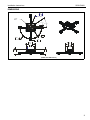
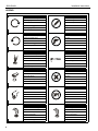
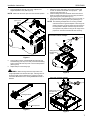
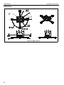
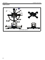
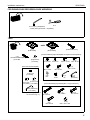
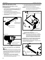
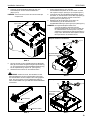
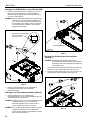
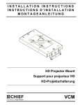
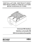
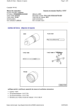
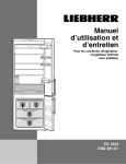
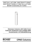
INSTALLATION INSTRUCTIONS
INSTRUCTIONS D'INSTALLATION
Instru
MONTAGEANLEITUNG
SLBU
SLMU
Universal Interface Brackets
Pattes de fixation d'interface universelles
Universalanschlussplatten
SLBU/SLMU
SLBU/SLMU
Installation Instructions
DISCLAIMER
Milestone AV Technologies and its affiliated corporations and
subsidiaries (collectively "Milestone"), intend to make this
manual accurate and complete. However, Milestone makes no
claim that the information contained herein covers all details,
conditions or variations, nor does it provide for every possible
contingency in connection with the installation or use of this
product. The information contained in this document is subject
to change without notice or obligation of any kind. Milestone
makes no representation of warranty, expressed or implied,
regarding the information contained herein. Milestone assumes
no responsibility for accuracy, completeness or sufficiency of
the information contained in this document.
Chief® is a registered trademark of Milestone AV Technologies.
All rights reserved.
IMPORTANT SAFETY WARNINGS!
WARNING: A WARNING alerts you to the possibility of
serious injury or death if you do not follow the instructions.
CAUTION: A CAUTION alerts you to the possibility of
damage or destruction of equipment if you do not follow the
corresponding instructions.
WARNING: Failure to read, thoroughly understand, and
follow all instructions can result in serious personal injury,
damage to equipment, or voiding of factory warranty! It is the
installer’s responsibility to make sure all components are
properly assembled and installed using the instructions
provided.
WARNING: Failure to provide adequate structural strength
for this component can result in serious personal injury or
damage to equipment! It is the installer’s responsibility to
make sure the structure to which this component is attached
can support five times the combined weight of all equipment.
Reinforce the structure as required before installing the
component.
WARNING: Exceeding the weight capacity can result in
serious personal injury or damage to equipment! It is the
installer’s responsibility to make sure the combined weight of
all components attached to the SLBU-SLMU interface
brackets does not exceed 50 lbs (22.68 kg).
WARNING: Use this mounting system only for its intended
use as described in these instructions. Do not use
attachments not recommended by the manufacturer.
2
WARNING: Never operate this mounting system if it is
damaged. Return the mounting system to a service center for
examination and repair.
WARNING: Do not use this product outdoors.
--SAVE THESE INSTRUCTIONS--
Installation Instructions
SLBU/SLMU
DIMENSIONS
95.2
Ø 3.75
BOLT CIRCLE
1 1/2"
NPT
4X 7.5°
4X 32.5°
6.7
4X Ø .27
190.2
R7.49
26.97
1.06
169.07
143.7
6.66
5.66
119
82.6
4.69
3.25
88.6
93
3.49
3.66
(SLBU with RMA shown)
3
SLBU/SLMU
Installation Instructions
LEGEND
4
Tighten Fastener
Pencil Mark
Apretar elemento de fijación
Marcar con lápiz
Befestigungsteil festziehen
Stiftmarkierung
Apertar fixador
Marcar com lápis
Serrare il fissaggio
Segno a matita
Bevestiging vastdraaien
Potloodmerkteken
Serrez les fixations
Marquage au crayon
Loosen Fastener
Drill Hole
Aflojar elemento de fijación
Perforar
Befestigungsteil lösen
Bohrloch
Desapertar fixador
Fazer furo
Allentare il fissaggio
Praticare un foro
Bevestiging losdraaien
Gat boren
Desserrez les fixations
Percez un trou
Phillips Screwdriver
Socket Wrench
Destornillador Phillips
Llave de cubo
Kreuzschlitzschraubendreher
Llave de cubo
Chave de fendas Phillips
Chave de caixa
Cacciavite a stella
Chiave a brugola
Kruiskopschroevendraaier
Dopsleutel
Tournevis à pointe cruciforme
Clé à douilles
Open-Ended Wrench
Remove
Llave de boca
Quitar
Gabelschlüssel
Entfernen
Chave de bocas
Remover
Chiave a punte aperte
Rimuovere
Steeksleutel
Verwijderen
Clé à fourche
Retirez
By Hand
Optional
A mano
Opcional
Von Hand
Optional
Com a mão
Opcional
A mano
Opzionale
Met de hand
Optie
À la main
En option
Hex-Head Wrench
Security Wrench
Llave de cabeza hexagonal
Llave de seguridad
Sechskantschlüssel
Sicherheitsschlüssel
Chave de cabeça sextavada
Chave de segurança
Chiave esagonale
Chiave di sicurezza
Zeskantsleutel
Veiligheidssleutel
Clé à tête hexagonale
Clé de sécurité
Installation Instructions
SLBU/SLMU
TOOLS REQUIRED FOR INSTALLATION
#2
1/4" (included)
5/32" (security - included)
PARTS
OR
A (1)
[SLBU Plate]
C (2)
[Security Cover Bracket]
[SLBU Only]
B (4)
[SLBU/SLMU Leg]
A (1)
[SLMU Plate]
[Universal Projector Interface Hardware Kit]
D (4)
[Thumb Nut]
[SLBU Only]
K (4)
8-32 x 3/8"
L (4)
8-32 x 1/4"
M (4)
M2.5 x 10mm
[All Points Security Kit]
P (4)
M4 x 10mm
E (2)
10-24 x 3/8"
[SLBU Only]
S (4)
M4
H (1)
G (4)
10-24 x 3/8" 5/16-18 x 1/2"
[SLBU Only] [SLBU Only]
R (4)
M6 x 12mm
Q (4)
M5 x 12mm
T (4)
1/4-20
N (4)
M3 x 10mm
U (1)
1/4"
V (1)
5/32"
(security)
[Universal Hardware Kit - Long Screws]
J (1)
5/32" (security)
[SLBU Only]
[No hardware
designated "F"]
W (4)
M3 x 25mm
Z (4)
M6 x 25mm
X (4)
M4 x 25mm
Y (4)
M5 x 25mm
AA (4)
.500 x .257 x .625
5
SLBU/SLMU
Installation Instructions
ASSEMBLY AND INSTALLATION
NOTE: Only use washers (S) if using M or N screws to attach
screw adapters to projector.
Remove Screw Adapters from SLBU/SLMU Legs
1.
Press locking buttons on SLBU/SLMU leg (B) firmly and
simultaneously push clip cover toward enclosed sliding stud
mount bracket and screw. (See Figure 1)
2.
Screw adapter and attached height-adjustment nut will be
released. Set aside for later use. (See Figure 1)
3.
Repeat Steps 1-2 for each leg to be used in installation.
2
(M, N, P, Q or R)
(S) x 3 or 4
(with M or N only)
(B)
1
sliding stud mount
bracket and screw
locking button x 2
clip cover
screw adapters
with nuts
Figure 2
3.
Adjust height-adjustment nuts to desired level.
Figure 3)
(See
NOTE: Height-adjustment nuts should be adjusted as low as
(side view)
possible while ensuring that the legs will always clear
any elevated surfaces on the projector. All nuts must be
adjusted to the same level to ensure an even mount.
IMPORTANT ! : The optional Universal Hardware Kit Long Screws (see Parts drawing) may be used if there is
interference with any part of the projector, and more
height is required to clear elevated surfaces of the
projector.
height-adjustment nut
2
screw adapter
Figure 1
3
Attach Projector to SLBU/SLMU
WARNING: Exceeding the weight capacity can result in
serious personal injury or damage to equipment! It is the
installer’s responsibility to make sure the combined weight of
all components attached to the SLBU-SLMU interface
brackets does not exceed 50 lbs (22.68 kg).
1.
2.
6
Determine proper size screw to insert into projector. Test
Phillips screws (M, N, P, Q and R) provided until one fits the
projector holes.
Insert screws through M4 flat washers (S), screw adapters
with height-adjustable nuts and into projector holes. (See
Figure 2)
fully lowered
Figure 3
Installation Instructions
4.
SLBU/SLMU
Place SLBU/SLMU legs (B) over screw adapters and
height-adjustment nuts. (See Figure 4)
NOTE: Make sure arm latch clips are in the unlocked position.
(B) x 3 or 4
7.
Manuever legs so that sliding stud mount brackets and
screws are towards the middle of the projector. (See
Figure 6) and (See Figure 7)
8. Position sliding stud mount brackets and screws so that
SLBU or SLMU main plate (A) can be evenly mounted to
legs. (See Figure 6) and (See Figure 7)
9. Use 1/4" hex key (U) to secure Allen nuts (T) to screws on
sliding stud mounts. (See Figure 6) and (See Figure 7)
NOTE: The following examples are two of many possible
scenarios based on typical examples of mounting hole
patterns. Specific connection points will vary based on
the hole pattern. Multiple scenarios may be used for
each specific hole pattern as long as the weight of the
projector is centered and balanced after mounting.
Three-hole scenario example
(T) x 3
9
(A)
sliding stud mount
brackets and
screws
Figure 4
5.
Press locking buttons on SLBU/SLMU leg (B) firmly and
simultaneously push clip cover away from enclosed sliding
stud mount bracket until clip cover is in the locked position.
(See Figure 5)
6.
Repeat Step 5 for remaining legs.
WARNING: Make sure legs have securely locked onto
height-adjustable nuts with the latch clips. If the legs are not
properly locked onto the adapters, the projector could fall
from the SLBU/SLMU mount causing SERIOUS INJURY or
DEATH!
Figure 6
Four-hole scenario example
(A)
5
locking buttons
9
(T) x 4
sliding stud mount
brackets and
screws
open position
locked position
Figure 5
Figure 7
7
SLBU/SLMU
Installation Instructions
Attach SLBU/SLMU to RPA or RPM
1.
On SLBU, partially install four thumb nuts (D) to SLBU main
plate screws. Be sure to install thumb nuts with tapered side
down. (See Figure 8)
NOTE: If using optional security brackets (C) to connect SLBU
bracket to RPA or non-locking RPM mount, refer to
Security Bracket Installation section prior to installing
thumb nuts.
(B)
1
(K)
Install thumb nuts
with tapered
side down
1
(D) x 4
security hole
Figure 9
Security Bracket Installation (Optional)
(A)
NOTE: Security brackets (C) can only be used when
connecting SLBU bracket to RPA or non-locking RPM
mounts.
1.
Install security brackets (C) over screws on SLBU main
plate. (See Figure 10)
2.
Partially install thumb nuts (D) onto SLBU main plate
screws. (See Figure 10)
(D) x 4
2
(C) x 2
Figure 8
2.
Attach SLBU/SLMU to RPA/RPM. Refer to RPA/RPM
installation manual for details.
Security Screw Installation (Optional)
1.
Install #8-32 x 3/8" button head security screws (K) into
security holes on SLBU/SLMU legs. (See Figure 9)
NOTE: Up to two security screws can be installed on each leg.
It is recommended that screws be installed in holes that
are difficult to access to achieve maximum security.
NOTE: Cable ties (not included) may be used instead of the
security screws. Thread cable tie through both holes on
leg and secure cable tie.
Figure 10
8
Installation Instructions
SLBU/SLMU
CLAUSES DE NON-RESPONSABILITÉ
Milestone AV Technologies, ses filiales et entreprises affiliées
(« Milestone ») ont fait en sorte que ce manuel soit exact et
exhaustif. Cependant, Milestone ne garantit pas que les
informations mentionnées au présent document couvrent tous
les aspects, conditions ou variations dans le détail ; pas plus
qu'elle ne fournit de solution pour chaque imprévu lié au type
d'installation ou d'utilisation de ce produit. Les informations
mentionnées au présent document sont susceptibles d'être
modifiées sans aucun préavis ni obligation. Milestone ne
consent aucune garantie, expresse ou implicite, au titre des
informations contenues dans le présent document. Milestone
ne garantit pas que les informations mentionnées au présent
document soient exactes, exhaustives et suffisantes.
AVERTISSEMENT : Le dépassement de capacité de poids
Chief® est une marque déposée de Milestone AV
Technologies. Tous droits réservés.
AVERTISSEMENT : Ne pas utiliser ce produit à l'extérieur.
DIRECTIVES DE SÉCURITÉ IMPORTANTES
peut causer de graves blessures corporelles ou endommager le
matériel ! Il est de la responsabilité de l'installateur de s'assurer
que le poids total de tous les composants fixés aux pattes
d'interface SLBU-SLMU ne dépasse pas 22,68 kg
(50 lbs).N'utiliser ce système de montage que pour l'usage
prévu conformément à ces directives. Ne pas utiliser
d'accessoires non recommandés par le fabricant.
AVERTISSEMENT : Ne jamais faire fonctionner ce système
de montage s'il est endommagé. Dans ce cas, renvoyer le
système à un service technique pour examen et réparation.
--RANGER CES CONSIGNES EN LIEU SÛR--
AVERTISSEMENT : Un AVERTISSEMENT vous indique
qu'il existe un risque de blessures graves ou de décès si
vous ne suivez pas les instructions.
MISE EN GARDE : Une MISE EN GARDE vous indique qu'il
existe un risque de dommages ou de destruction du matériel si
vous ne suivez pas les instructions correspondantes.
AVERTISSEMENT : Le fait de ne pas lire, de ne pas bien
comprendre et de ne pas suivre toutes les instructions peut
entraîner des blessures corporelles graves, endommager
l'équipement ou annuler la garantie du fabricant ! Il est de la
responsabilité de l'installateur de s'assurer que tous les
composants sont correctement montés et installés
conformément aux instructions fournies.
AVERTISSEMENT : Une résistance structurelle non
appropriée pour ce composant peut entraîner des blessures
corporelles graves ou endommager l'équipement ! Il est de la
responsabilité de l'installateur de s'assurer que la structure à
laquelle ce composant est attaché peut supporter cinq fois le
poids total de l'équipement. Si nécessaire, renforcez la
structure avant d'installer cet élément.
9
SLBU/SLMU
Installation Instructions
DIMENSIONS
,
,
CERCLE DE
BOULONNAGE
,
,
,
,
,
,
,
,
,
,
,
,
,
,
(SLBU avec RMA représenté)
10
Installation Instructions
SLBU/SLMU
OUTILS NÉCESSAIRES À L'INSTALLATION
#2
6,4 mm (1/4") (inclus)
4,0 mm (5/32") (sécurité - inclus)
PIÈCES
OU
A (1)
[Plaque SLBU]
B (4)
[Pied SLBU/SLMU]
A (1)
[Plaque SLMU]
[Kit de matériel d'interface pour projecteur universel]
C (2)
[ Patte du couvercle de sécurité]
[SLBU uniquement]
D (4)
[Écrou à ailettes]
[SLBU uniquement]
K (4)
8-32 x 3/8"
L (4)
8-32 x 1/4"
M (4)
M2.5 x 10 mm
[Kit de sécurité All-Points]
P (4)
M4 x 10 mm
N (4)
M3 x 10 mm
R (4)
M6 x 12mm
Q (4)
M5 x 12mm
E (2)
10-24 x 3/8"
[SLBU uniquement]
G (4)
H (1)
10-24 x 3/8"
5/16-18 x 1/2"
[SLBU uniquement]
S (4)
M4
[SLBU uniquement]
T (4)
1/4-20"
U (1)
1/4"
V (1)
5/32"
(sécurité)
[Kit de matériel universel - Vis longues]
J (1)
5/32" [4,7625] (sécurité)
[SLBU uniquement]
[Aucun matériel
désigné « F »]
W (4)
M3 x 25mm
Z (4)
M6 x 25mm
X (4)
M4 x 25mm
Y (4)
M5 x 25mm
AA (4)
0,500 x 0,257 x 0,625
11
SLBU/SLMU
Installation Instructions
MONTAGE ET INSTALLATION
1.
Retrait des adaptateurs à vis des pieds
SLBU/SLMU
2.
1.
Appuyez fermement sur les boutons de verrouillage situés
sur le pied SLBU/SLMU (B) en poussant simultanément le
couvercle enclipsé vers la patte et la vis de fixation des
montants coulissants fournis. (See Figure 1)
2.
L'adaptateur à vis et l'écrou de réglage de la hauteur fourni
seront relâchés. Mettre de côté pour une utilisation
ultérieure. (See Figure 1)
3.
Répétez les étapes 1-2 pour chaque pied à utiliser lors de
l'installation.
Déterminez la taille de vis correcte à insérer dans le projecteur.
Testez les vis Phillips (M, N, P, Q et R) fournies jusqu'à ce que
l'une d'entre elles rentre dans les trous du projecteur.
Insérez les vis dans les rondelles plates M4 (S), les
adaptateurs à vis avec les écrous de réglage de la hauteur
dans les trous du projecteur. (See Figure 2)
REMARQUE : Utilisez uniquement des rondelles (S) si vous
utilisez des vis M ou N pour fixer les adaptateurs
à vis au projecteur.
2
(M, N, P, Q ou R)
(S) x 3 ou 4
(avec M ou
N uniquement)
(B)
1
patte et vis de fixation
des montants coulissants
2 boutons de verrouillage
couvercle enclipsé
adaptateurs à vis
avec écrous
Figure 2
3.
(vue latérale)
Ajustez les écrous de réglage de la hauteur au niveau
souhaité. (See Figure 3)
REMARQUE : Les écrous de réglage de la hauteur doivent être
ajustés le plus bas possible en faisant en sorte que
les pieds passent sous toute surface surélevée du
projecteur. Tous les écrous doivent être ajustés au
même niveau pour assurer un montage uniforme.
écrou de réglage de
la hauteur
adaptateur à vis
2
Figure 1
IMPORTANT ! : Le Kit de matériel universel - Vis longues (voir
dessin Pièces) en option peut être utilisé en cas d'interférence
avec l'une des pièces du projecteur. Une plus grande hauteur
est requise pour dégager les surfaces élevées du projecteur.
3
Fixation du projecteur au SLBU/SLMU
AVERTISSEMENT : Le dépassement de capacité de poids
peut causer de graves blessures corporelles ou endommager
le matériel ! Il est de la responsabilité de l'installateur de
s'assurer que le poids total de tous les composants fixés aux
pattes d'interface SLBU-SLMU ne dépasse pas 22,68 kg
(50 lbs).
complètement
abaissé
Figure 3
12
Installation Instructions
4.
SLBU/SLMU
Placez les pieds SLBU/SLMU (B) sur les adaptateurs à vis
et les écrous de réglage de la hauteur. (See Figure 4)
REMARQUE : Assurez-vous que les clips de bras de
verrouillage sont en position verrouillée.
(B) x 3 ou 4
7.
Manœuvrez les pieds pour que les pattes et les vis de
fixation des montants coulissants se trouvent vers le milieu
du projecteur. (See Figure 6) et (See Figure 7)
8. Positionnez les pattes et les vis de fixation des montants
coulissants de manière à permettre un montage uniforme de
la plaque principale SLBU ou SLMU (A) aux pieds. (See
Figure 6) et (See Figure 7)
9. Utilisez une clé hexagonale de 1/4" (U) pour fixer les écrous
Allen (T) aux vis sur les montants de fixation coulissants.
(See Figure 6) et (See Figure 7)
REMARQUE : Les exemples suivants vous indiquent deux
scénarios possibles parmi d'autres en se basant sur
les exemples caractéristiques des configurations de
trous de fixation. Les points de raccordement
spécifiques peuvent varier en fonction de la
configuration des trous. Plusieurs scénarios
peuvent être utilisés pour chaque configuration de
trous spécifique, tant que le poids du projecteur est
centré et équilibré après le montage.
Exemple de scénario à trois trous
(T) x 3
9
(A)
patte et vis
de fixation
des montants
coulissants
Figure 4
5.
Appuyez fermement sur les boutons de verrouillage situés sur
le pied du SLBU/SLMU (B) en repoussant simultanément le
couvercle enclipsé de la patte de fixation des montants
coulissants fournis, jusqu'à ce que le couvercle enclipsé soit
en position verrouillée. (See Figure 5)
6.
Répétez l'étape 5 pour les autres pieds.
AVERTISSEMENT : Assurez-vous que les pieds sont
verrouillés sur les écrous de réglage de la hauteur avec les
clips de verrouillage. Si les pieds ne sont pas verrouillés
correctement sur les adaptateurs, le projecteur pourrait
tomber du support du SLBU/SLMU et causer DES
BLESSURES GRAVES ou LA MORT !
Figure 6
Exemple de scénario à quatre trous
(A)
9
(T) x 4
patte et vis de fixation
des montants
coulissants
5
boutons de
verrouillage
position ouverte
position verrouillée
Figure 5
Figure 7
13
SLBU/SLMU
Installation Instructions
Fixation du SLBU/SLMU au RPA ou RPM
1.
Sur le SLBU, installez en partie quatre écrous à ailettes (D)
aux vis de la plaque principale du SLBU. Assurez-vous
d'installer les écrous à ailettes avec des roulements
coniques sur l'envers. (See Figure 8)
REMARQUE : Si vous utilisez des pattes de sécurité en option
(C) pour connecter la patte SLBU au montant
RPA ou RPM non verrouillé, référez-vous à la
section Installation des pattes de sécurité avant
d'installer les écrous à ailettes.
(B)
1
(K)
Installez les écrous à ailettes
avec des roulements coniques
sur l'envers
1
(D) x 4
trou de sécurité
Figure 9
Installation des pattes de sécurité (en option)
REMARQUE : Les pattes de sécurité (C) peuvent uniquement
(A)
être utilisées en connectant la patte SLBU aux
montants RPA ou RPM non verrouillés.
1.
Installez les pattes de sécurité (C) sur les vis de la plaque
principale du SLBU. (See Figure 10)
2.
Installez en partie des écrous à ailettes (D) aux vis de la
plaque principale du SLBU. (See Figure 10)
(D) x 4
2
(C) x 2
Figure 8
2.
Fixez le SLBU/SLMU au RPA/RPM. Référez-vous au
manuel d'installation du RPA/RPM pour plus de détails.
Installation des vis de sécurité (en option)
1.
Installez les vis de sécurité à tête bouton #8-32 x 3/8" (K)
dans les trous de sécurité des pieds du SLBU/SLMU.
(See Figure 9)
REMARQUE : Plus de deux vis de sécurité peuvent être
installées sur chaque pied. Il est recommandé
que les vis soient installées dans les trous
difficilement accessibles pour un maximum
de sécurité.
REMARQUE : Des attaches de câble (non incluses) peuvent
être utilisées à la place des vis de sécurité. Faites
passer les attaches de câble par les deux trous
situés sur le pied et fixez-les.
14
Figure 10
Installation Instructions
SLBU/SLMU
HAFTUNGSAUSSCHLUSS
Milestone AV Technologies sowie seine konzerneigenen
Unternehmen und Tochtergesellschaften (zusammen "Milestone")
haben versucht, dieses Handbuch so genau und vollständig als
möglich zu gestalten. Milestone erhebt jedoch weder Anspruch auf
Vollständigkeit der Einzelheiten, Bedingungen und Änderungen
der hierin enthaltenen Informationen, noch übernimmt das
Unternehmen irgendeine Haftung für eventuelle Schadensfälle in
Verbindung mit der Installation oder Verwendung dieses Produkts.
Die in diesem Dokument enthaltenen Informationen können ohne
vorherige Ankündigung oder sonstige Verpflichtungen jederzeit
geändert werden. Milestone schließt jegliche ausdrückliche oder
stillschweigende Zusicherung und Gewährleistung bezüglich der
hierin enthaltenen Informationen aus. Milestone übernimmt
keinerlei Verantwortung für die Genauigkeit, Vollständigkeit oder
Angemessenheit der in diesem Dokument enthaltenen
Informationen.
WARNUNG: Verwenden Sie das Halterungssystem nur für
den vorgesehenen, in der Anleitung beschriebenen Zweck.
Verwenden Sie keine Zubehörteile, die nicht vom Hersteller
empfohlen wurden.
WARNUNG: Verwenden Sie das Halterungssystem nie in
beschädigtem Zustand. Bringen Sie das Halterungssystem in
diesem Fall für die Fehlersuche und Reparatur zu einem
Service-Center.
WARNUNG: Verwenden Sie das Produkt nie im Freien.
--BEWAHREN SIE DIESE ANWEISUNGEN AUF--
Chief® ist eine eingetragene Marke von Milestone AV
Technologies. Alle Rechte vorbehalten.
WICHTIGE SICHERHEITSHINWEISE
WARNUNG: WARNUNG weist darauf hin, dass bei
Nichtbefolgung der Anweisungen Verletzungs- oder
Lebensgefahr besteht.
VORSICHT: VORSICHT weist darauf hin, dass bei
Nichtbefolgung der Anweisungen die Möglichkeit von
Geräteschäden besteht.
WARNUNG: Die Nichtbefolgung dieser Anweisungen kann
zu schweren Verletzungen und Geräteschäden sowie zum
Erlöschen der Garantie führen. Der Monteur hat dafür zu
sorgen, dass alle Bauelemente nach den beiliegenden
Anweisungen montiert und installiert werden.
WARNUNG: Wenn dieses Bauelement nicht an einer
Konstruktion mit der erforderlichen Tragfähigkeit montiert
wird, kann dies zu schweren Verletzungen oder
Geräteschäden führen! Der Monteur hat dafür zu sorgen,
dass die Konstruktion, an der das Bauelement angebracht
wird, über die erforderliche Tragfähigkeit verfügt.
Die Konstruktion muss das fünffache Gesamtgewicht des
Geräts tragen können. Verstärken Sie vor der Montage des
Bauelements ggf. die Konstruktion.
WARNUNG: Das Überschreiten der maximalen Tragkraft
kann zu schweren Verletzungen oder Geräteschäden führen!
Der Monteur ist dafür verantwortlich, sicherzustellen, dass
das Gesamtgewicht aller Komponenten, die mit der SLBU/
SLMU-Anschlussplatte verbunden sind, 22,68 kg (50 lbs)
nicht überschreitet.
15
SLBU/SLMU
Installation Instructions
ABMESSUNGEN
,
,
LOCHKREIS
,
,
,
,
,
,
,
,
,
,
,
,
,
,
(SLBU mit RMA dargestellt)
16
Installation Instructions
SLBU/SLMU
FÜR DIE MONTAGE ERFORDERLICHES WERKZEUG
Nr. 2
6,4 mm (1/4") (mitgeliefert)
4,0 mm (5/32") (Sicherheit – mitgeliefert)
TEILE
ODER
A (1)
[SLBU-Platte]
B (4)
[SLBU/SLMU-Bein]
A (1)
[SLMU-Platte]
[Universal-Befestigungsmaterialpaket für Projektoranschlussplatten]
C (2)
[Sicherheitsabdeckplatte]
[nur SLBU]
D (4)
[Flügelmutter]
[nur SLBU]
K (4)
8-32 x 3/8"
L (4)
8-32 x 1/4"
M (4)
M2,5 x 10 mm
[All-Points-Sicherheitspaket]
P (4)
M4 x 10 mm
E (2)
10-24 x 3/8"
[nur SLBU]
H (1)
G (4)
10-24 x 3/8" 5/16-18 x 1/2"
[nur SLBU] [nur SLBU]
S (4)
M4
R (4)
M6 x 12 mm
Q (4)
M5 x 12 mm
T (4)
1/4-20
N (4)
M3 x 10 mm
U (1)
1/4"
V (1)
5/32"
(Sicherheit)
[Universal-Befestigungsmaterialpaket - Lange Schrauben]
J (1)
5/32" (Sicherheit)
[nur SLBU]
[Kein Befestigungsmaterial
mit der Bezeichnung "F"]
W (4)
M3 x 25 mm
Z (4)
M6 x 25 mm
X (4)
M4 x 25mm
Y (4)
M5 x 25 mm
AA (4)
.500 x .257 x .625
17
SLBU/SLMU
Installation Instructions
MONTAGE UND INSTALLATION
2.
Entfernen der Schraubadapter von den
SLBU/SLMU-Beinen
HINWEIS: Verwenden Sie die Unterlegscheiben (S) nur,
1.
Drücken Sie fest auf die Feststellknöpfe am SLBU/SLMU-Bein
(B) und schieben Sie gleichzeitig die Clip-Abdeckung in
Richtung der eingeschlossenen Schiebebalkenhalterplatte mit
der Schraube. (See Figure 1)
2.
Der Schraubadapter und die daran befestigte
Höheneinstellmutter werden freigegeben. Legen Sie die
Teile für einen späteren Gebrauch beiseite. (See Figure 1)
3.
Führen Sie die Schrauben durch die M4-Unterlegscheiben
(S) und die Schraubadapter mit den Höheneinstellmuttern
in die Projektorlöcher ein. (See Figure 2)
wenn Sie M- oder N-Schrauben zur Befestigung der
Schraubadapter am Projektor benutzen.
2
(M, N, P, Q oder R)
(S) x 3 oder 4
(nur mit M oder N)
Wiederholen Sie die Schritte 1-2 für jedes zu
montierende Bein.
(B)
1
Schiebebalkenhalterplatte mit Schraube
Feststellknopf x 2
Clip-Abdeckung
Schraubadapter
mit Muttern
Abb. 2
3.
Schrauben Sie die Höheneinstellmuttern auf die
gewünschte Höhe. (See Figure 3)
HINWEIS: Sie sollten die Höheneinstellmuttern so niedrig wie
(Seitenansicht)
möglich platzieren, aber darauf achten, dass die Beine
eventuelle Erhebungen am Projektor nicht streifen.
Für eine ebene Ausrichtung der Halterung müssen
alle Muttern auf die gleiche Höhe gebracht werden.
WICHTIG! Wird ein Teil des Projektors gestreift und ist
eine größere Höhe erforderlich, damit Erhebungen am
Projektor frei bleiben, können Sie das optionale
Universal-Befestigungsmaterialpaket – Lange Schrauben
(siehe Abb. Teile) heranziehen.
Höheneinstellmutter
2
Schraubadapter
Abb. 1
3
Anbringen des Projektors an der SLBU/SLMU
WARNUNG: Das Überschreiten der maximalen Tragkraft
kann zu schweren Verletzungen oder Geräteschäden führen!
Der Monteur ist dafür verantwortlich, sicherzustellen, dass
das Gesamtgewicht aller Komponenten, die mit der SLBU/
SLMU-Anschlussplatte verbunden sind, 22,68 kg (50 lbs)
nicht überschreitet.
1. Bestimmen Sie die für Ihren Projektor passende
Schraubengröße. Probieren Sie die mitgelieferten
Kreuzschlitzschrauben (M, N, P, Q und R) aus, bis eine
davon in die Löcher Ihres Projektors passt.
18
ganz nach unten
geschraubt
Abb. 3
Installation Instructions
4.
SLBU/SLMU
Platzieren Sie die SLBU/SLMU-Beine (B) über den
Schraubadaptern mit den Höheneinstellmuttern.
(See Figure 4)
7.
HINWEIS: Achten Sie darauf, dass die Armverschlussclips
8.
entsperrt sind.
9.
(B) x 3 oder 4
Richten Sie die Beine so aus, dass die
Schiebebalkenhalterplatten mit den Schrauben zur Mitte
des Projektors zeigen. (See Figure 6) und (See Figure 7)
Positionieren Sie die Schiebebalkenhalterplatten mit den
Schrauben so, dass die SLBU- oder SLMU-Hauptplatte (A)
in ebener Lage auf die Beine montiert werden kann.
(See Figure 6) und (See Figure 7)
Befestigen Sie die Inbusmuttern (T) mit einem 1/4"Inbusschlüssel (U) an die Schrauben auf den
Schiebebalkenhalterungen. (See Figure 6) und (See Figure 7)
HINWEIS: Die folgenden Beispiele stellen zwei
von vielen möglichen Szenarien typischer
Befestigungsschemata dar. Je nach Lochbild gibt
es unterschiedliche Anschlusspunkte. Für jedes
spezifische Lochbild kommen mehrere Szenarien in
Frage, sofern das Gewicht des Projektors nach der
Montage zentriert und ausbalanciert ist.
Beispiel mit Drei-Loch-Szenario
(T) x 3
9
(A)
Schiebebalkenhalterplatten mit Schrauben
Abb. 4
5.
Drücken Sie fest auf die Feststellknöpfe am SLBU/SLMUBein (B) und schieben Sie gleichzeitig die Clip-Abdeckung
von der eingeschlossenen Schiebebalkenhalterplatte weg,
bis die Clip-Abdeckung versperrt ist. (See Figure 5)
6.
Wiederholen Sie Schritt 5 für die restlichen Beine.
WARNUNG: Stellen Sie sicher, dass die Beine auf den
Höheneinstellmuttern mit den Verschlussclips sicher fixiert
sind. Sind die Beine auf den Adaptern nicht ordnungsgemäß
fixiert, kann der Projektor aus der SLBU/SLMU-Halterung
fallen und SCHWERE oder gar TÖDLICHE VERLETZUNGEN
verursachen!
Abb. 6
Beispiel mit Vier-Loch-Szenario
(A)
9
(T) x 4
Schiebebalkenhalterplatten mit
Schrauben
5
Feststellknöpfe
offene Position
gesperrte Position
Abb. 5
Abb. 7
19
SLBU/SLMU
Installation Instructions
Anbringen der SLBU/SLMU an einer RPA oder RPM
1.
Bei einer SLBU montieren Sie vier Flügelmuttern (D) ein
Stück weit auf die Schrauben der SLBU-Hauptplatte.
Montieren Sie die Flügelmuttern mit der konischen Seite
nach unten. (See Figure 8)
HINWEIS: Falls Sie optionale Sicherheitsanschlussplatten (C)
verwenden, um die SLBU-Anschlussplatte an die
RPA- oder die nicht-verriegelnde RPM-Halterung
anzuschließen, lesen Sie den Abschnitt "Montage
der Sicherheitsanschlussplatten", bevor Sie die
Flügelmuttern anbringen.
(B)
1
(K)
Montieren der Flügelmuttern
mit der konischen
Seite nach unten
1
Sicherheitsbohrung
(D) x 4
Abb. 9
Montage der Sicherheitsanschlussplatten
(optional)
HINWEIS: Sicherheitsanschlussplatten (C) können nur
(A)
verwendet werden, wenn eine SLBU-Anschlussplatte
an eine RPA- oder nicht-verriegelnde RPM-Halterung
angeschlossen wird.
1.
Montieren Sie die Sicherheitsanschlussplatten (C) über den
Schrauben an der SLBU-Hauptplatte. (See Figure 10)
2.
Montieren Sie die Flügelmuttern (D) ein Stück weit auf die
Schrauben der SLBU-Hauptplatte. (See Figure 10)
(D) x 4
2
(C) x 2
Abb. 8
2.
Bringen Sie die SLBU/SLMU an der RPA/RPM an.
Informationen dazu finden Sie im RPA/RPMMontagehandbuch.
Anbringen von Sicherheitsschrauben (optional)
1.
Montieren Sie Nr. 8-32 x 3/8"-HalbrundkopfSicherheitsschrauben (K) in die Sicherheitsbohrungen der
SLBU/SLMU-Beine. (See Figure 9)
HINWEIS: Pro Bein können bis zu zwei Sicherheitsschrauben
angebracht werden. Für ein Höchstmaß an
Sicherheit empfiehlt es sich, die Schrauben in
schwer zugängliche Löcher zu montieren.
HINWEIS: Statt der Sicherheitsschrauben können auch (nicht
mitgelieferte) Kabelbinder verwendet werden.
Führen Sie den Kabelbinder durch beide Löcher am
Bein und befestigen Sie ihn.
20
Abb. 10
Installation Instructions
SLBU/SLMU
21
SLBU/SLMU
22
Installation Instructions
Installation Instructions
SLBU/SLMU
23
SLBU/SLMU
Installation Instructions
USA/International
Europe
Chief Manufacturing, a products division
of Milestone AV Technologies
8800-002419 Rev00
2013 Milestone AV Technologies, a
Duchossois Group Company
www.chiefmfg.com
05/13
Asia Pacific
A
P
F
A
P
F
A
6436 City West Parkway, Eden Prairie, MN 55344
800.582.6480 / 952.225.6000
877.894.6918 / 952.894.6918
Franklinstraat 14, 6003 DK Weert, Netherlands
+31 (0) 495 580 852
+31 (0) 495 580 845
Office No. 1 on 12/F, Shatin Galleria
18-24 Shan Mei Street
Fotan, Shatin, Hong Kong
P 852 2145 4099
F 852 2145 4477