1
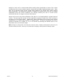
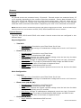
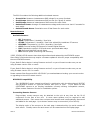
Instruction Manual Rack Power Distribution Unit RCX, RCO, RCM-O and RCU-O Series Firmware Version 3 Geist. 1821 Yolande Ave., Lincoln, NE 68521 800.432.3219 | 402.474.3400 | F: 402.474.4369 | www.geistglobal.com Contents Contents ............................................................................................................................ 2 Specifications .................................................................................................................... 4 Overview 4 Environmental 4 Electrical 4 Receptacle Ratings 4 Networking 4 Data Formats 5 EMC Verification 5 Installation ....................................................................................................................... 6 Guidelines 6 Mounting 7 Network Overview 13 Default IP Address 13 Initial Setup 14 Web Interface ................................................................................................................. 16 Overview 16 Sensors Page 16 Logging Page 18 Display Page 19 Alarms Page 20 Control Page (RCM-O and RCU-O Only) 21 Configuration Page 23 Unit Configuration ........................................................................................................... 28 Network Configuration 28 Time and Date 29 E-Mail/ Business Hours 30 SNMP 31 Accounts and Passwords 32 Telnet 33 Camera Configuration 33 Admin Information 34 Kilowatt-Hours Reset 34 XML File Backup 35 SSL Certificate Upload 35 Alarms ............................................................................................................................. 36 Alarm Notifications 36 Alarm Types 36 Thresholds 36 Sensors ........................................................................................................................... 38 Overview 38 Internal Sensors 38 Remote Sensors 39 Data Logging and Display 40 Remote Outlet Switching (RCM-O and RCU-O Only) ........................................................ 41 Actions 41 Configuration 42 Power-On Actions 42 Accessories ..................................................................................................................... 43 Serial Communication (Delta Configured Units Only) 43 RSD2X8 Remote Display 43 IP-Addressable Network Cameras 43 GM1111 2 Revision Date 6/22/2012 RSC Integration 44 Alternate Data Formats 44 Technical Support ........................................................................................................... 45 Firmware Version 45 Firmware Updates 45 Resetting PDU 45 Service and Maintenance 45 More Technical Support 45 Table of Figures .............................................................................................................. 46 Revision History 48 GM1111 3 Revision Date 6/22/2012 Specifications Overview The RCM-O, RCU-O, RCO and RCX series units are rack level PDUs with circuit monitoring via a built-in web server. In the RCX series, built-in sensors monitor Voltage, Current, instantaneous and cumulative Power, as well as calculated Power Factor. The RCM-O series units have all these sensors plus outlet level switching. The RCO series units have the same built-in sensors as the RCX plus outlet level current and power monitoring, while RCU-O series units have all of the RCX sensors plus outlet level switching plus current and power monitoring. Web pages, including graphs, are generated by the unit to monitor power and environmental conditions within the cabinet. No software other than a web browser is required for operation and several data formats are available. Optional external sensors and network cameras are also available. These units can be built for installation in either Delta or Wye building wiring configurations. Environmental Temperature Operating (Vertical): Operating (Horizontal): Storage: 10°C (50°F) min 10°C (50°F) min -25°C (-13°F) min 40°C (104°F) max 45°C (113°F) max 65°C (149°F) max Humidity Operating: Storage: 5% min 5% min 95% max 95% max (non-condensing) (non-condensing) Elevation Operating: Storage: 0 m (0 ft) min 0 m (0 ft) min 2000 m (6561 ft) max 15240 m (50000 ft) max Electrical See nameplate for unit ratings. Receptacle Ratings NEMA 5-15R or L5-15R 125 Volts, 15 Amp NEMA 5-20R or L5-20R 125 Volts, 20 Amp NEMA 6-20R or L6-20R 250 Volts, 20 Amp NEMA L5-30R 125 Volts, 30 Amp NEMA L6-30R 250 Volts, 30 Amp NEMA L15-30R 250 Volts (3 phase), 30 Amp IEC-320 C13 125/250 Volt, 15 Amp (per Receptacle Bank) IEC-320 C19 125/250 Volt, 20 Amp Networking Protocols HTTP, HTTPS (SSL/TLS), SMTP, POP3, ICMP, DHCP, TCP/IP, NTP, Telnet, Syslog GM1111 4 Revision Date 6/22/2012 Ethernet Link Speed 10 Mbit; half-duplex Data Formats HTML, SNMP, CSV/Plain Text, XML EMC Verification This Class A device complies with part 15 of the FCC Rules. Operation is subject to the following two conditions: (1) This device may not cause harmful interference, and (2) this device must accept any interference received, including interference that may cause undesired operation. This Class A digital apparatus complies with Canadian ICES-003. Cet appareil numérique de la classe A est conforme à la norme NMB-003 du Canada. Warning: Changes or modifications to this unit not expressly approved by the party responsible for compliance could void the user’s authority to operate this equipment. GM1111 5 Revision Date 6/22/2012 Installation Guidelines • • • • • • • • • • GM1111 If the PDU is installed in a cabinet the ambient temperature of the rack should be no greater than the PDU’s maximum rated operating temperature. Install the PDU such that the amount of airflow required for safe operation of equipment is not compromised. Mount the PDU so that a hazardous condition is not achieved due to uneven mechanical loading. Follow nameplate ratings when connecting equipment to the branch circuit. Take into consideration the effect that overloading of the circuits might have on over-current protection and supply wiring. The PDU relies on the building installation for protection from over-current conditions. A Listed circuit breaker is required within the building installation. The circuit breaker should be sized according to the PDU’s nameplate ratings and local/national electrical codes. Reliable earthing of rack-mount equipment should be maintained. Particular attention should be given to supply connections other than direct connections to the branch circuit. The PDU must be connected to an earthed socket-outlet. The PDU is intended for Restricted Access Locations only and only service personnel should install and access the PDU. For pluggable equipment, install the PDU so that the input plug or appliance coupler may be disconnected for service. Sequential power-up via Power-On Actions of devices powered by the PDU is recommended to avoid high inrush current. See Power-On Actions (page 42) for details. Caution: Disconnect all power cords before servicing. 6 Revision Date 6/22/2012 Mounting Figure 1: Full Length Bracket Using the full length bracket, mount PDU to rack as shown Figure 2: Mini "L" Brackets Using the mini “L” brackets, attach PDU to rack as shown GM1111 7 Revision Date 6/22/2012 Figure 3: Vertical Extension Brackets Using the vertical extension brackets, attach PDU to rack as shown Figure 4: Toolless Mounting Hardware Secure toolless mounting buttons to PDU as shown. Use toolless buttons with key-holed slots built into cabinet or with optional Geist key-holed brackets. GM1111 8 Revision Date 6/22/2012 Figure 5: Toolless Full Length Bracket Using full length toolless bracket and toolless mounting buttons, attach PDU to rack as shown Figure 6: Single Side Mount 2 Unit Brackets Using single side mount 2 unit brackets and toolless mounting buttons, attach PDU to rack as shown GM1111 9 Revision Date 6/22/2012 Figure 7: Offset/Side Mount Brackets Using the offset/side mount brackets, attach PDU to rack as shown. Figure 8: 7" Extension Brackets Using the 7” extension brackets, attach PDU to rack as shown GM1111 10 Revision Date 6/22/2012 Figure 9: Flush Mount Brackets Using flush mount brackets, attach PDU to rack as shown Figure 10: Adjustable Mount Brackets Using adjustable mount brackets, attach PDU to rack as shown GM1111 11 Revision Date 6/22/2012 Figure 11: Panel Mount Brackets Using panel mount brackets, attach PDU to rack as shown Figure 12: 23" Conversion Mounting Brackets Using conversion mounting brackets, attach 19” PDU to 23” rack as shown GM1111 12 Revision Date 6/22/2012 Figure 13: 19" Horizontal/Panel Mount Brackets Using the 19” horizontal/panel mount brackets, attach PDU to rack as shown Network Overview This product comes preconfigured with a default IP address set. Simply connect to the PDU and access the web page with your browser. Default IP Address RCX, RCO, RCM-O and RCU-O units have a default IP address for initial setup and access to the unit if the assigned address is lost or forgotten. Once an IP address is assigned to a unit, the default IP address is no longer active. To restore the default IP address, press and hold the reset button located below the network connector for 20 seconds while the unit is powered up. The Idle and Activity lights next to the network connector will both light up when the IP address has been reset. The reset button is accessed through the white, circular hole located below the Ethernet jack. Note: Pressing the reset button under the network connector will restore the default IP address and will also clear all password settings. The Configuration page allows you to assign the network properties or use DHCP to connect to your network. Access to the unit requires the IP address to be known, so use of a Static IP or reserved DHCP is recommended. The default address is shown on the front of the unit: • • • GM1111 IP Address: Subnet Mask: Gateway: 192.168.123.123 255.255.255.0 192.168.123.1 13 Revision Date 6/22/2012 Initial Setup Connect the RCX, RCO, RCM-O or RCU-O series unit to your computer using a crossover cable or hub/switch. Windows XP On your computer, go to “Start > Settings > Control Panel > Network and Dial Up Connections” Right click on “Local Area Connection” and select “Properties” Select “Use the following IP address”. Use these settings: IP Address: Subnet Mask: Gateway: 192.168.123.1 255.255.255.0 Leave blank Click “OK” twice. The unit should now be accessible in a web browser via the unit’s permanent IP address: http://192.168.123.123/. See Unit Configuration (page 28) for details. Figure 14: Windows XP network settings for initial setup. MacOS X 10.5 and 10.6 Open System Preferences via the Dock or the Apple menu. Select “Network” under “Internet & Network.” Select “Ethernet” from the list on the left side of the window and enter these settings on the right side of the window: GM1111 14 Revision Date 6/22/2012 Configure: IP Address: Subnet Mask: Router: Manually 192.168.123.1 255.255.255.0 Leave blank Hit “Apply” and confirm the changes. The unit should now be accessible in a web browser via the unit’s permanent IP address: http://192.168.123.123/. See Unit Configuration (page 28) for details. Figure 15: MacOS X network settings for initial setup Note: Problems connecting to the local PDUs may be caused by the use of proxy servers. Turn off “Use a proxy server for your LAN” or select “Bypass proxy server for local addresses” under your web browser’s LAN settings. Figure 16: Internet Explorer's LAN Settings for selecting proxy settings GM1111 15 Revision Date 6/22/2012 Web Interface Overview The unit is accessible via a standard, unencrypted HTTP connection as well as an encrypted HTTPS (SSL) connection. The following web pages are available: Sensors Page The front page, Sensors, gives both instantaneous and historical views of the unit’s data. Real time readings are provided for all power strip data, outlet group data (RCO and RCU-O only), and sensor data next to historical graphs. For units configured for Wye wiring all readings are based on the line currents; A, B, C. For units configured for Delta wiring current readings are based on input line current (A, B, C). All other readings (Voltage, Real/Apparent Power, Power Factor and kWatt-Hours) are based on the Phase-to-Phase Load (AB, BC, CA). Optional cameras may be added and their live snapshots are shown on this page. Plug-andplay sensors appear below the internal sensors when attached. The menu bar allows access to the rest of the PDU’s functionality. Alternate formats for the real-time data can be downloaded in PDA, XML and SNMP formats, and historical data is available in PDA format. Figure 17: Sensors Page – Wye Configuration GM1111 16 Revision Date 6/22/2012 Figure 18: Sensors Page – Delta Configuration Figure 19: Sensors Page – Group and Sensor Data GM1111 17 Revision Date 6/22/2012 Logging Page The Logging page allows the user to access the historical data by selecting the desired sensors and time range to be logged. The Sensor Measurement Data Graph section contains check boxes which allow the user to select which readings are to be graphed on the Logging page and/or displayed on the internal LCD (Delta configuration only) or RSD2X8 remote display module. The “Logging Control” allows users to select between different modes of logging data. • Normal: Data logged once per minute into data log file. • High-water Mark: High value logged each minute into the data log file. • Low-water Mark: Low value logged each minute into the data log file. • Logging Off The data will be logged into the data file at a rate of one point per minute and will be available for graphing and display. Please note that although data is logged once per minute, all sensor data used in the real time display and alarm functions is read at least once every 15 seconds for internal sensors and once every 30 seconds for external sensors. Recorded data is available for download in a comma-separated values (CSV) file. To reset the logs click the “Reset Logs” check box and save the changes. Figure 20: Logging Page GM1111 18 Revision Date 6/22/2012 Display Page The Display page allows the user to assign friendly names to attached sensors, change the default unit of measure for all temperature sensors, and change what is scrolling on the LCD display (Measurements or Alarms). The display page also allows the user to select between the default and classic web page layouts. The default interface displays a vertical menu bar to the left of the main window (shown in Figure 19), while the classic interface displays a horizontal menu bar across the top of the screen. Figure 21: Display Page GM1111 19 Revision Date 6/22/2012 Alarms Page The Alarms page allows the user to establish alarm conditions for each sensor reading. Alarm conditions can be established with either high or low trip thresholds. The alarms are displayed in different sections based on the device the alarm is associated with. Alarm options include a local Buzzer (with RSD attached), Email and SNMP Trap. See Alarms (page 36) for more details. Figure 22: Alarms Page GM1111 20 Revision Date 6/22/2012 Control Page (RCM-O and RCU-O Only) The Control page has two sub-tabs; Actions and Settings. See Remote Outlet Switching (page 41) for details. Control Actions Tab The Actions tab on the Control page gives the user control of the outlets. Outlets can be rebooted or turned on/off with or without pre-programmed delays. The status of each outlet is also shown for verification by the user. For RCU-O series units, outlet readings for current, power and logged kilowatt-hours are also shown. Figure 23: Control Actions Tab GM1111 21 Revision Date 6/22/2012 Control Settings Tab The Settings tab on the Control page allows the user to name and define a URL for outlets in addition to setting time delays for each outlet action. Boot up status and sequential boot up options are also available. All delay settings are referenced from the trigger event. This tab also allows the user to restore factory default settings for the outlets. Figure 24: Control Settings Tab GM1111 22 Revision Date 6/22/2012 Configuration Page The Configuration page has five sub-tabs; Network, Monitoring, Diagnostics, Event Log, and Admin. See Unit Configuration (page 28) for details. Configuration Network Tab The user can enter and update the network settings on the Network tab of the Configuration page. See Unit Configuration section for details. Figure 25: Configuration Network Tab GM1111 23 Revision Date 6/22/2012 Configuration Monitoring Tab The user can enter and update the email alert, SNMP, and camera settings on the Monitoring tab of the Configuration page. See Unit Configuration section for details. Figure 26: Configuration Monitoring Tab GM1111 24 Revision Date 6/22/2012 Configuration Diagnostics Tab The user can update the Syslog settings on the Diagnostics tab of the Configuration page. Figure 27: Configuration Diagnostics Tab GM1111 25 Revision Date 6/22/2012 Configuration Event Log Tab The user can view the Event Log and update the Memory Syslog settings on the Event Log tab of the Configuration page. Figure 28: Configuration Event Log Tab GM1111 26 Revision Date 6/22/2012 Configuration Admin Tab The user can set the system clock and administrative information on this tab. Additionally, the user can set administrator and account passwords. See Unit Configuration section for details. Figure 29: Configuration Admin Tab GM1111 27 Revision Date 6/22/2012 Unit Configuration Network Configuration The unit’s network configuration is set on the Network tab of the Configuration page. Settings pertaining to the unit’s network connection are: Figure 30: Network Configuration • • DHCP: Allows the unit to request a dynamic IP address from a server on the network. Static IP Address/Net Mask/Gateway: When not using a dynamic address, enter static network configuration information here. Telnet Service: Enable or disable the built-in Telnet server. See • • • • GM1111 Telnet (page 33) for details. HTTP Services: Enables/disables access via HTTP and HTTPS. Available options are: HTTP and HTTPS, HTTP only, and HTTPS only. It is not possible to disable the web interface completely. HTTP/HTTPS Server Port: Changes the TCP port that each server listens on. DNS Servers: Allows the unit to resolve host names for Email, NTP and SNMP servers as well as cameras. 28 Revision Date 6/22/2012 Time and Date The system clock is set on the Admin tab of the Configuration page. The unit comes preconfigured with the IP addresses of two NIST time servers and is set to the Central Time Zone (-0500 GMT). Should a local time server be preferred, select “NTP Server” from the “Set Clock method” drop-down menu, enter its IP address into the “NTP primary server” box and click “Save Changes”. Clearing the time server addresses and clicking “Save Changes” will set the time servers back to the defaults. The unit attempts to contact the time servers during boot up and periodically while running. Until a time server is contacted or the system clock is manually set, all log time stamps will present time as the number of seconds since the unit was powered up and graphs will not be shown. The clock can also be setup to automatically change for Daylight Savings Time when needed. When enabled, the user can select the dates and times for the clocks to adjust. Note: Enabling automatic DST or setting the time zone offset forward and backward will cause a gap or overwriting of logs. Figure 31: Manual Time Settings Figure 32: NTP Time Settings GM1111 29 Revision Date 6/22/2012 The time, date, IP address and friendly name of the unit are displayed at the top of each web page. Figure 33: Time and Date Display E-Mail/ Business Hours The e-mail and business hours configuration are set on the Monitoring tab of the Configuration page. The unit is capable of sending e-mail to as many as five addresses at once. Most SMTP and ESMTP servers are compatible. Authentication options are None, POP3 (POP-before-SMTP) or ESMTP. The unit can be configured to send alarm emails always, only during business hours or only after hours by selecting the desired option next to each email address. Figure 34: E-Mail Configuration GM1111 30 Revision Date 6/22/2012 An SMTP server as well as “From” and “To” addresses are required to send e-mails. Some mail servers may require a username and password. In most cases, the username does not have to match the “From” address, but does need to be a valid user on the authenticating server. Microsoft Exchange servers will have to be set to allow SMTP relay from the IP address of the unit. In addition, a test email can be sent from the bottom of the Monitoring tab of the Configuration page. Note: The unit cannot receive e-mails. The POP3 server is used strictly for authentication and is not required when the protocol is set to ESMTP or None. Status Reports When enabled, the unit will periodically send a full status report to all “To” e-mail addresses selected for the report. The report includes current unit data from all attached sensors as well as alarm states. Reporting frequency options are: weekly, hourly, every 2, 3, 4, 6, 8, 12, 24, or 48 hours. E-mail addresses are selected when the report is created by checking the corresponding e-mail destination box. Allowing the cursor to hover over an e-mail destination box will display the e-mail address that the box is associated with. Figure 35: Email Report Settings SNMP The unit supports retrieval of all data via Simple Network Management Protocol (SNMP) v1, v2c, and v3. In addition, alarm traps can be sent to up to two IP addresses. The SNMP configuration is entered on the Monitoring tab of the Configuration page. Figure 36: SNMP Configuration Figure 37: Initial SNMP V3 Data The default community string is “public” and the MIB is downloadable via a link on the web pages menu bar. GM1111 31 Revision Date 6/22/2012 Accounts and Passwords The RCX, RCO, RCU-O and RCM-O offer account security options that are entered on the Admin tab of the Configuration page. There are three levels of account security: • • • Administrator: Password protects the Display, Alarms and Configuration pages along with protecting the Telnet and Serial access. Control Access: Password protects the Control Actions and Control Settings pages. View-Only: Password protects the Sensors, PDA, WAP and XML pages. Figure 388: Account Configuration User account names may include alphanumeric characters, spaces and underscores. Passwords may include alphanumeric characters and underscores. Note: The Administrator account must be active to enable the Control Access and View-Only accounts. Note: The Control Access account must be active to enable the View-Only account. Note: The account names “root” and “admin” are disabled for security reasons and cannot be re-enabled. Warning: Record your passwords. To reset lost passwords, follow the instructions for resetting the unit’s IP address and passwords given in the Default IP Address section. To generate a temporary recovery password to access the unit, contact customer service from a location where the unit can be accessed via the internet. GM1111 32 Revision Date 6/22/2012 Telnet The unit provides a Telnet server for basic monitoring via the command line. The Administrator account must be enabled to use the Telnet interface. Type “help” after logging in to the unit to see a list of available commands. The Telnet service can be disabled under “Web Server” on the Network tab of the Configuration page. Note: All data sent via Telnet is unencrypted. Some settings can be changed and user names and network settings are available via Telnet. In unsecure environments, it is recommended that Telnet be disabled. Camera Configuration Enter the domain names/IP addresses and models of up to four IP-addressable network cameras in the “Cameras” section of the Monitoring tab on the Configuration page. The unit will present a linked snapshot from each camera on the Sensors page. Figure 39: Configuration and Supported Models Note: Each camera must be set to allow anonymous access to enable this feature. GM1111 33 Revision Date 6/22/2012 Admin Information Information entered in the “Admin Info” section of the Admin tab of the Configuration page will show up at the bottom of the unit’s web interface. Figure 40: Admin Information Fields Figure 41: Admin Information Display Kilowatt-Hours Reset The RCX, RCO, RCU-O and RCM-O’s kilowatt-hours measurements are zeroed at the factory and can be reset at any time, should it become necessary. On the Admin tab of the Configuration page, simply hit the button that corresponds to the desired circuit to be reset. Figure 42: Kilowatt Hours Reset GM1111 34 Revision Date 6/22/2012 XML File Backup The RCX, RCO, RCU-O or RCM-O unit’s configuration is stored in the XML file. The XML file can be downloaded and stored in order to backup the unit’s current configuration settings. On the Admin tab of the Configuration page, simply hit the Download Current XML File button to download the XML file. A previously downloaded XML file can be uploaded to the unit in order to restore the unit’s configuration to match the configuration contained in the XML file. On the Admin tab of the Configuration page, click the Upload Local XML file button to upload a local XML file. Note: XML files are unit specific, and should only be uploaded to the unit that it was downloaded from. Figure 43: XML File Upload SSL Certificate Upload The unit will automatically generate a unique SSL Certificate and Private Key. Alternatively, a custom SSL Certificate and Private Key can be uploaded to the unit by pressing the “Upload SSL Files” button on the Admin tab of the Configuration page. The SSL certificate and key file must be in Distinguished Encoding Rules (DER) format. The SSL Certificate and Private Key can be cleared by clicking the “Erase SSL Data” button on the Admin tab of the Configuration page. Figure 44: SSL Certificate and Private Key Upload GM1111 35 Revision Date 6/22/2012 Alarms Alarm Notifications The RCX, RCO, RCU-O and RCM-O support three types of alarm notification: • • • E-Mail: The unit can be configured to send alarm e-mails to up to five recipients. SNMP: The unit can be configured to send SNMP traps to up to two trap servers. Buzzer: When a remote display (RSD2X8) is attached, the unit can turn on an audible alarm. The unit is capable of any combination of the above alarms at once. Alarm type combinations are selected per alarm via the check boxes which are displayed for each alarm on the Alarms page. Figure 45: Alarm State Menu Alarm Types The RCX, RCO, RCU-O and RCM-O provide three types of alarm messages via E-Mail and SNMP: • • • Trip: Occurs when a sensor value goes above a high trip threshold or below a low trip threshold. Unplugged: Occurs when a sensor with an alarm set loses contact with the main unit due to the sensor being physically unplugged or another communications error. Unplugged alerts can be enabled or disabled on the Alarms page. Clear: Occurs when a sensor already in the Tripped or Unplugged state goes back into its normal range. Alarms can be added for each internal device or external sensor displayed on the Alarms page. An alarm is added by pressing the “Add New Alarm Button” and selecting the sensor value to be monitored from the drop down menu. Thresholds The user must set a trip threshold and type for each alarm that is added to the Alarms page. The threshold type is chosen as either “Below” or “Above” from a drop down menu when the alarm is created. The threshold value is typed into a data window when the alarm is created. Alarms are triggered based on the selected sensor’s data and the trip threshold type and value. Alarm settings can be edited or deleted at any time. GM1111 36 Revision Date 6/22/2012 Analysis of each unit is recommended before setting alarm thresholds as some of the values monitored by the unit are relative values, whose scale will differ slightly between units. Allow each unit to operate under normal, steady state conditions for several hours before setting alarm thresholds. By allowing the sensors to operate for several hours, the user can better understand what the normal variations are; thereby allowing the user to choose alarm thresholds that will not trigger numerous false alarms. Alarms can be set to only send notification if the alarm is in a tripped state for a certain amount of time. The user sets the amount of time required by entering a value from 0-240 minutes in the text box on the Alarms page. Additionally, alarm notifications can be set to send multiple notifications for an alarm that remains in a tripped state. The alarm notifications are set to repeat at intervals of no repeat, 10, 30, or 60 minutes by selecting the desired option in the drop down menu on the Alarms page. Note: Changes in settings take a few moments to become active. Rapidly resetting alarm values may not provide the desired results. Allow up to 2 minutes after changing a setting before modifying it again. GM1111 37 Revision Date 6/22/2012 Sensors Overview All internal sensors are measured every 15 seconds. External sensors are measured every 15 to 30 seconds, depending on the number of devices connected. Sensor data collected by the RCX, RCO, RCU-O and RCM-O unit gives useful trend analysis data. While all values are not absolute in relation to a known unit, trend analysis of the data allows users to view changes and draw useful conclusions about what is happening over time in the monitored environment. Note: DM series units are connected as sensors and collect a large amount of data. These will take longer than the usual 15 to 30 second for the RCX, RCO, RCU-O and RCM-O units to measure. Internal Sensors The RCX, RCO, RCU-O and RCM-O units contain internal sensors that are configured in two different ways: Wye Configuration • Total Unit • Kilowatt-Hours: Cumulative sum of Real Power for all lines. Real Power: Total average of instantaneous voltage and current on all lines over last 1.5 seconds. Line Level (A, B, C): o o o o o o o o o o Kilowatt-Hours: Cumulative sum of Real Power. Volts: Measures instantaneous RMS voltage. Volts (Peak): Reports the highest reported voltage since the last time the data was updated, typically every 15 seconds. Real Power: Average of instantaneous voltage and current over last 1.5 seconds. Apparent Power: The product of instantaneous RMS Voltage and RMS Current. Power Factor: The ratio of Real Power to Apparent Power. Amps: Measures instantaneous RMS current. Amps (Peak): Reports the highest reported current since the last time the data on the screen Delta Configuration • Total Unit • Kilowatt-Hours: Cumulative sum of Real Power for all lines. Real Power: Total average of instantaneous voltage and current on all lines over last 1.5 seconds. Phase Level (AB, BC, CA): • Kilowatt-Hours: Cumulative sum of Real Power. Volts: Measures instantaneous RMS voltage. Volts (Peak): Reports the highest reported voltage since the last time the data was updated, typically every 15 seconds. o Real Power: Average of instantaneous voltage and current over last 1.5 seconds. o Apparent Power: The product of instantaneous RMS Voltage and RMS Current. o Power Factor: The ratio of Real Power to Apparent Power. Line Level (A, B, C): o o o o o o GM1111 Amps: Measures instantaneous RMS current. 38 Revision Date 6/22/2012 The RCU-O contains the following additional onboard sensors: • • • • • Group Volts: Measures instantaneous RMS voltage for a group of outlets. Group Amps: Measures instantaneous RMS current for a group of outlets. Outlet Amps: Measures instantaneous RMS current for each outlet. Outlet Real Power: Average of instantaneous voltage and current over last 1.5 seconds for each outlet. Outlet Kilowatt-Hours: Cumulative sum of Real Power for each outlet. Remote Sensors Available Sensors: RT: Temperature GTHD: Temperature / Humidity / Dew Point GT3HD: Temperature / Humidity / Dew Point with ability to add two RT sensors RTAFHD3: Temperature / Air Flow / Humidity / Dew Point CCAT: Converts analog I/O Sensors to Remote Digital Sensors IOE: Expands the number of I/O and sensor ports and adds relays DM: Remote digital RMS current Meter RS2: Remote power monitoring and switching *RTAF, RTAFH & RTHD sensors have been discontinued and replaced by the RTAFHD3 sensor. Some Geist R-Series devices may require a firmware update to allow for proper compatibility with the new RTAFHD3 sensors. If your Geist R-Series device is using firmware version 2.xx you will want to make sure you are using firmware version 2.94 or newer. If your Geist R-Series device is using firmware version 3.xx you will want to make sure you are using firmware version 3.5.0 or newer. Please contact Geist Support at 800-432-3219 if you need assistance locating your current version or upgrading to the new firmware version RTAFHD3 Compatibility The (G)RTAFHD3 sensor cannot be utilized in combination with the discontinued (G)RTAF and (G)RTAFH sensors or (G)RTHD sensors built prior to 2010. If you desire to add (G)RTAFHD3 sensors to an existing installation currently utilizing incompatible sensors, please contact Customer Service for installation options. Connecting Remote Sensors Plug-and-play remote sensors may be attached to the unit at any time via the RJ-12 connectors on the face of the unit. In some cases splitters may be required to add additional sensors. Each sensor has a unique serial number and is automatically discovered and added to the web page. Up to sixteen sensors may be connected (15 on RCU-O). The display order of the sensors on the web page is determined by the serial number of each sensor. Friendly names for each sensor can be customized on the Display page. GM1111 39 Revision Date 6/22/2012 Note: The sensors use Cat. 3 wire and RJ12 connectors. Wiring must be straight-through: reverse polarity will temporarily disable all sensors until corrected. Note: The sensors use a low voltage serial communication protocol and are subject to network signaling constraints dependent on shielding, environmental noise, and length of wire. Typical installations allow runs of up to 600 feet of sensor wire. Data Logging and Display All sensor data collected by the unit can be graphed, except kilowatt-hours and outlet level data (RCU-O only). The Logging page allows the user to select data to be logged. The user can also choose to view a graph of any logged data. Selected sensor values are logged into the data file at a rate of one point per minute. The number of selected sensors determines the maximum data logging time span. This period is calculated and displayed on the Logging page. The oldest data will be deleted when the onboard memory fills up in order to make room for new data. Sensor values can also be selected for display on the local LCD or optional Remote Display (RSD2X8). GM1111 40 Revision Date 6/22/2012 Remote Outlet Switching (RCM-O and RCU-O Only) Actions The RCM-O and RCU-O Series are equipped with individually switchable outlets. There are seven possible actions for any given outlet, available from the “Action” drop down box on the Actions tab of the Control page: Figure 46: Outlet Actions • • • • • • • • On – Immediate: Turns on all selected outlets with no delay. On – Delayed: Turns on all selected outlets with applicable delays. Off – Immediate: Turns off all selected outlets with no delay. Off – Delayed: Turns off all selected outlets with applicable delays. Reboot: Cycles power to the selected outlets with one applicable delay. Each outlet is powered-down immediately, then “Reboot Duration” sets the delay after power-down and before power-up. Reboot-Delayed: Cycles power to the selected outlets with two applicable delays. “Reboot” delays before power down, and “Reboot Duration” sets the delay after power-down and before power-up. Reset kWh: Resets the kWh total on all selected outlets to 0. (RCU-O only) Cancel Actions: Cancels any actions currently in progress on the selected outlets. Figure 47: Outlet Action Confirmation To perform an action, select the check box next to the outlets needing attention, select an action from the drop down box and click the “Execute” button. A dialog box will appear asking for confirmation of the selected actions. Click OK to execute the action. Click cancel to make changes or ignore the action. Note: “Reboot”, Reboot-Delayed” and “On/Off-Delayed” actions are subject to the delays set on the Settings Tab of the Control page. GM1111 41 Revision Date 6/22/2012 Configuration The RCM-O and RCU-O series units list all available outlets under “Configuration” on the Settings tab of the Control page. Each outlet has five fields associated with it: Figure 48: Outlet Configuration • • • • • • Name: A friendly name to easily identify what is plugged into the outlet. For example: “Mail Server” URL: A URL associated with the equipment plugged into the outlet. This will appear as a clickable link on the Control Actions Tab next to the outlet status information. Power-On Delay: Delay from the time the “On – Delayed” action is executed until the outlet will turn on. Power-Off Delay: Delay from the time the “Off – Delayed” action is executed until the outlet will turn off. Reboot: Delay from the time the “Reboot-Delayed” action is executed to the time the selected outlets will be turned off. Reboot Duration: Delay from the time the “Reboot” or “Reboot-Delayed” action is executed and each selected outlet has turned off until the outlet will turn back on. Note: All delays are in seconds. Power-On Actions The state of each of the unit’s switched outlets on unit power-up is user configurable by setting a power-on action. Available settings are: • • • • Delay: Used in conjunction with On and Last actions to allow sequencing of outlet power-up to prevent overloading circuit breakers with inrush current. Off: Leaves the outlet off until turned on manually via the Control Actions page. On: Turns the outlet on. Last: Returns the outlet to its state prior to the unit losing power. Figure 49: Outlet Power-On Action Configuration Tip: To emulate legacy RCM or RCU behavior for a particular outlet, set the delay to 0 and action to On. Note: Outlets with their delay values set to 0 will perform the selected action immediately upon receiving power. Note for units with built-in circuit breakers: Should one of the unit’s circuit breakers trip, upon being reset any outlets powered by that breaker will perform their power-on actions. GM1111 42 Revision Date 6/22/2012 Accessories Serial Communication (Delta Configured Units Only) The Delta configured units provide an out-of-band, serial line, monitoring interface. The unit provides an RJ-45 port for RS-232 serial communication, giving monitoring via the command line similar to the Telnet service. If the administrator name and password are setup then they must be used to access the serial command line. Type “help” after logging-in to the unit to see a list of available commands. Note: All data sent via the serial port is unencrypted. Some settings can be changed and user names and network settings are available. Figure 50: Serial Command RSD2X8 Remote Display This small module comes standard with any Wye configured units (optional for Delta and Horizontal units) and can be mounted in an accessible spot inside or outside the rack or cabinet. A backlit LCD display scrolls the values of items selected on the Logging page. The display is connected to the main unit via a 4-conductor handset-style cord. The display’s onboard buzzer can be used in conjunction with E-Mail and SNMP to provide local alarming of error conditions. The buzzer can be silenced via the button on the face of the module; however the display’s LED indicator will remain lit until the alarm condition is cleared. IP-Addressable Network Cameras The unit is able to interface with up to four IP-addressable network cameras. A live snapshot from each camera will be displayed on the unit’s Sensors page underneath the main unit’s graph. Clicking on a snapshot opens the camera’s website in a new browser window. GM1111 43 Revision Date 6/22/2012 Figure 51: Camera Images Camera model and IP address are entered on the Monitoring tab of the Configuration page. Note: Some cameras require additional software downloads to display live video in a web browser. RSC Integration For users with multiple units, Geist RSC software offers: • • • Convenient, single-window monitoring of multiple units via simple web-based interface Streamlined firmware updating Consolidation of alarm settings See http://www.geistmfg.com/ for more information. Alternate Data Formats In addition to the full access, control and configuration available via a desktop web browser, RCX, RCO, RCU-O and RCM-O Series products present data in multiple formats for easy integration with other monitoring systems. Data formats available via links on the unit’s web page are: Figure 52: Alternate Format Links • • • GM1111 PDA/Phone: Presents data in a format best-suited for PDA or cellular phone web browsers. XML: Extensible Markup Language. Presents data in a structured tree for use with automated scripts and monitoring systems. MIB: Management Information Base. Downloads the MIB for use with SNMP monitoring tools. 44 Revision Date 6/22/2012 Technical Support Firmware Version The firmware version is located in the upper right section of the web interface header, represented by v3.y.xx. Before contacting support, it is recommended that the PDU first be updated to the latest firmware version. If this is not possible, please have the existing firmware version number for the unit available when contacting technical support. Figure 53: Web Page Header Firmware Updates Keep your unit updated with the latest firmware releases or sign up for notifications. http://www.geistglobal.com/support. Resetting PDU Should the PDU loose communication, the processor may be manually rebooted without affecting power to the outlets. Pressing the ‘Reset’ button on the face of the unit will cause the processor to reboot. The web interface will remain off-line during boot up. Service and Maintenance No service or maintenance is required. Do not attempt to open the PDU or you may void the warranty. No serviceable parts inside. It is recommended that power be removed from the unit before installing or removing any equipment. More Technical Support http://www.geistglobal.com (800) 432-3219 Email: [email protected] Or contact your distributor. GM1111 45 Revision Date 6/22/2012 Table of Figures Figure Figure Figure Figure Figure Figure Figure Figure Figure Figure Figure Figure Figure Figure Figure Figure Figure Figure Figure Figure Figure Figure Figure Figure Figure Figure Figure Figure Figure Figure Figure Figure Figure Figure Figure Figure Figure Figure Figure Figure Figure Figure Figure Figure Figure Figure Figure Figure Figure Figure Figure Figure GM1111 1: Full Length Bracket ................................................................................................. 7 2: Mini "L" Brackets .................................................................................................... 7 3: Vertical Extension Brackets ...................................................................................... 8 4: Toolless Mounting Hardware ................................................................................... 8 5: Toolless Full Length Bracket ..................................................................................... 9 6: Single Side Mount 2 Unit Brackets ............................................................................ 9 7: Offset/Side Mount Brackets.................................................................................... 10 8: 7" Extension Brackets ........................................................................................... 10 9: Flush Mount Brackets ............................................................................................ 11 10: Adjustable Mount Brackets ................................................................................... 11 11: Panel Mount Brackets .......................................................................................... 12 12: 23" Conversion Mounting Brackets ........................................................................ 12 13: 19" Horizontal/Panel Mount Brackets ..................................................................... 13 14: Windows XP network settings for initial setup. ........................................................ 14 15: MacOS X network settings for initial setup ............................................................. 15 16: Internet Explorer's LAN Settings for selecting proxy settings .................................... 15 17: Sensors Page – Wye Configuration ........................................................................ 16 18: Sensors Page – Delta Configuration....................................................................... 17 19: Sensors Page – Group and Sensor Data ................................................................. 17 20: Logging Page ..................................................................................................... 18 21: Display Page ...................................................................................................... 19 22: Alarms Page ....................................................................................................... 20 23: Control Actions Tab ............................................................................................. 21 24: Control Settings Tab ........................................................................................... 22 25: Configuration Network Tab ................................................................................... 23 26: Configuration Monitoring Tab ............................................................................... 24 27: Configuration Diagnostics Tab .............................................................................. 25 28: Configuration Event Log Tab ................................................................................ 26 29: Configuration Admin Tab ..................................................................................... 27 30: Network Configuration ......................................................................................... 28 31: Manual Time Settings .......................................................................................... 29 32: NTP Time Settings .............................................................................................. 29 33: Time and Date Display ........................................................................................ 30 34: E-Mail Configuration ............................................................................................ 30 35: Email Report Settings .......................................................................................... 31 36: SNMP Configuration ............................................................................................ 31 37: Initial SNMP V3 Data ........................................................................................... 31 388: Account Configuration ....................................................................................... 32 39: Configuration and Supported Models ..................................................................... 33 40: Admin Information Fields ..................................................................................... 34 41: Admin Information Display ................................................................................... 34 42: Kilowatt Hours Reset ........................................................................................... 34 43: XML File Upload .................................................................................................. 35 44: SSL Certificate and Private Key Upload .................................................................. 35 45: Alarm State Menu ............................................................................................... 36 46: Outlet Actions .................................................................................................... 41 47: Outlet Action Confirmation ................................................................................... 41 48: Outlet Configuration ............................................................................................ 42 49: Outlet Power-On Action Configuration.................................................................... 42 50: Serial Command ................................................................................................. 43 51: Camera Images .................................................................................................. 44 52: Alternate Format Links ........................................................................................ 44 46 Revision Date 6/22/2012 Figure 53: Web Page Header ............................................................................................... 45 GM1111 47 Revision Date 6/22/2012 Revision History Revision 0.0 0.1 0.2 0.3 1.0 1.1 1.2 1.3 1.4 1.5 GM1111 Date 4/27/11 10/14/10 10/15/10 5/3/11 5/10/11 5/11/11 7/29/11 4/9/12 4/27/2012 6/22/2010 Notes Initial Delta Version Original RCM-O/RCU-O – GM1085 Original RCX – GM1094 Combined RCM, RCU, RCX with Delta configuration Initial Combined Version New Alarms Image LCD added to RCU-OH Added RCO Added GT3HD and GTHD Change logo and web address 48 Approved By CG BP BP CG CG CG CG CG CG SR Revision Date 6/22/2012