1
CM598G
STOP
READ ALL OF THE FOLLOWING INSTRUCTIONS BEFORE
REMOVING
CABINET FROM SKID
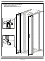
NET-ACCESS N-Type Network Cabinets
TOOL LIST
-Phillips screwdriver
-Flatblade screwdriver
-22mm socket wrench
-15mm socket wrench
-13mm socket wrench
-8mm socket wrench
-7mm socket wrench
-T30 Torx bit
-T25 Torx bit
-6mm Allen key
-2.5mm Allen key
-Wire cutter
NET-ACCESS N-Type Network Cabinets
(Switch Configurations)
INSTRUCTIONS CM598G
© Panduit Corp. 2012-2013
NOTE - Some views in this document may vary
slightly from your actual cabinet configuration.
FOR TECHNICAL SUPPORT www.panduit.com/resources/install_maintain.asp
Page 2 of 28
INSTRUCTIONS CM598G
Table of Contents - Net-Access N-Type Network Cabinets
General Cabinet Operation
Page
Packaging Material Removal……………………………………………...…………… 4-5
Leveling…………………………..………………………………………………………6
Floor Mounting………………………………………………………………………… 7
Ganging………………………………………………………………………………… 8
Grounding……………………………………………………………………………… 9
Equipment Rail Adjustment………………………………………………………………
10
Overhead Cable Openings………………………………………………………………11
Cable Management Fingers Installation (SN15F, SN25F)………………………………12
Dual Hinge Door (Operation, Removal, and Installation) …………………………….. 13-15
Single Hinge Door (Removal and Installation) …………………………………………16-17
Rear Split Doors (Removal and Installation) ……………………………………………18
In-Row Side Panel (Removal and Installation) …………………………………………19
Split/Hinged Side Panels Installation (N21SPH, N22SPH, N51SPH, N52SPH)……… 20-21
Caster Kit Installation (NCSTR4)…………………………………….…………………22
PDU Bracket Kit Installation (NVPDUB)……………………………………..…………
23
Cabinet Seal Kit Installation……………………………………..………………..…… 24
Front and Back Floor Seals………………………………………………………………
25
Top of Cabinet Cable Manager Installation………………………………………………
26
Top of Cabinet Cable Manager Installation (for vertical exhaust ducts) ……………… 27
Note: The maximum static weight load of the cabinet is 3000 lbs. [1361 kg]. The maximum
weight load when the cabinet is rolling on casters is 2500 lbs. [1134 kg]. The weight load should
be evenly distributed across the height of the cabinet, with the heaviest components mounted at
the bottom of the cabinet.
For Technical Support: www.panduit.com/resources/install_maintain.asp
Page 3 of 28
INSTRUCTIONS CM598G
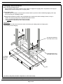
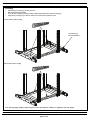
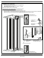
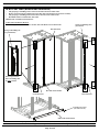
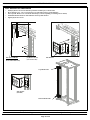
Packaging Material Removal
Before removal of packaging material:
Check tip indicator on the outside of cabinet to ensure cabinet was shipped in the upright position. If tip indicator shows improper
handling, inspect cabinet for damage before accepting cabinet.
Before handling cabinet:
Small glide strips are installed at various locations around the cabinet to protect the cabinet’s finish during shipping. These strips
are to be removed prior to handling of cabinet.
“Shipping Hold Down Bracket” Doubles as Floor Mounting Bracket. Retain bracket if floor mounting is desired. (see Page 7)
•
Remove all stretchwrap and protective cardboard from outside of cabinet
•
Remove [2] Hold Down Brackets at front and rear of cabinet
•
Use [2] people to carefully lift and remove cabinet from pallet
IMPORTANT:
Leveling Legs must be fully retracted before the cabinet is moved into place. Sliding cabinet on leveling legs may
result in damage to the leveling legs.
[4] Lag Bolts and Washers
(use 13mm socket wrench)
[4] M10 Hex Head Screws
(use 15mm socket wrench)
[2] Shipping
Hold Down
Brackets
Pallet
Note: Doors, Side panels, and other components are removed for clarity.
For Technical Support: www.panduit.com/resources/install_maintain.asp
Page 4 of 28
INSTRUCTIONS CM598G
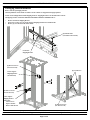
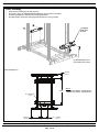
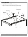
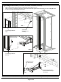
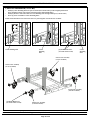
Packaging Material Removal
Before removal of packaging material:
Check tip indicator on the outside of cabinet to ensure cabinet was shipped in the upright position.
NOTE: Not all configurations include shipping brackets. Shipping Brackets to be discarded after removal.
All shipping brackets are labeled “SHIPPING BRACKET REMOVE IMMEDIATELY”
•
•
•
Remove Front Door Shipping Bracket
If necessary, remove up to [4] Center Support Shipping Brackets from cabinet frame
Remove [2] Cross Braces from cabinet frame
[2] M14 Hex Nuts
(use 22mm socket wrench)
Front Door
Shipping Bracket
[2] M5 Torx Screws
(use T25 Torx bit)
[2] Cross Braces
Center Support
Shipping Bracket
(No Side Panel)
[4] M5 Torx Screws
(use T25 Torx bit)
Center Support
Shipping Bracket
(Side Panel)
•
Loosen screws
•
Squeeze bracket
•
Remove and discard
[4] M5 Torx Screws
(use T25 Torx bit)
For Technical Support: www.panduit.com/resources/install_maintain.asp
Page 5 of 28
INSTRUCTIONS CM598G
Leveling
•
•
•
•
Ensure that [4] Leveling Legs are fully retracted
Slide Cabinet into final position
Lower the [4] Leveling Legs until the cabinet weight is fully supported by only the leveling legs
Adjust the [4] Leveling Legs so that the cabinet is level front-to-back and side-to-side
Front-to-Back Cabinet Leveling
[4] Leveling Legs
(use 6mm Allen Key)
Side-to-Side Cabinet Leveling
Note: When ganging multiple cabinets together, ensure that adjacent cabinets are adjusted to the same height.
For Technical Support: www.panduit.com/resources/install_maintain.asp
Page 6 of 28
INSTRUCTIONS CM598G
Floor Mounting
•
•
•
•
Ensure that [4] Leveling Legs are fully retracted
If Necessary, secure [2] “Shipping Hold Down Brackets” at front and rear of cabinet
See Floor Mounting View below for floor mounting dimensions
Attach the anchors to the floor with appropriate hardware for your type of floor
[2] Shipping
Hold Down
Brackets
[4] M10 Hex Head Screws
(use 15mm socket wrench)
Floor Mounting View
131mm
[5.16”]
DIM A
4X 14mm DIA
[0.55”]
291mm
[11.46”]
2X
DIM A:
-1070mm deep cabinets: 782mm [30.79”]
-1200mm deep cabinets: 912mm [35.91”]
216mm
[8.50”]
For Technical Support: www.panduit.com/resources/install_maintain.asp
Page 7 of 28
INSTRUCTIONS CM598G
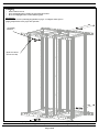
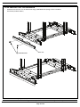
Ganging
•
•
•
Ensure cabinets are level
Secure Ganging Brackets to cabinets at [4] locations shown below
Do not use Ganging Brackets to cinch cabinets together
IMPORTANT:
Ensure cabinets are level by following the guidelines on page 6. Leveling the cabinet prior to
ganging is important to ensure proper door operation.
[4] Ganging
Brackets
[8] M6 Torx Screws
(use T25 Torx bit)
For Technical Support: www.panduit.com/resources/install_maintain.asp
Page 8 of 28
INSTRUCTIONS CM598G
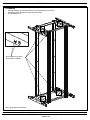
Grounding
•
•
•
Attach Grounding Lug or Grounding Bar at any of the [8] location(s) shown below
Grounding location is indicated by universal ground symbol
Use M5 bonding screw
[8] Grounding Lug Locations
(Front and Rear of Beams)
Note: top cap removed for clarity.
For Technical Support: www.panduit.com/resources/install_maintain.asp
Page 9 of 28
INSTRUCTIONS CM598G
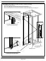
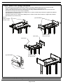
Equipment Rail Adjustment
•
Loosen M10 Hex Head Screw at top and bottom of rear equipment rail
•
Adjust equipment rail to desired positon
•
Tighten M10 Hex Head Screw to 30.0 +/- 5.0 N-m [22.1 +/- 3.7 Ft-lbs]
NOTE: Front equipment rails are in a fixed position
Uninstall/Re-install and Move Equipment Rails (Top and Bottom Locations)
•
Remove [2] M10 Hex Screws at top and bottom of Equipment Rail
•
Remove [2] Equipment Rail Mount Nuts through slots of Front-to-Back Beam
•
REVERSE STEPS to re-install Equipment Rails (insert Equipment Rail Mount Nuts through slots of Front-to-Back beam while holding
finger grip of mount nut; ensure that barbed surface of Equipment Rail Mount Nut faces outside of cabinet)
M10 Hex Head Screw
(use 15mm socket wrench)
Equipment Rail
Mount Nut
(Finger Grip Area)
Barbed Surface
(face to outside
of cabinet)
UNINSTALL/RE-INSTALL AND MOVE EQUIPMENT RAILS
Equipment Rail
Mount Nut
M10 Hex Head Screw
(use 15mm socket wrench)
Slot of Front-to-Back Beam
M10 Hex Head Screw
(use 15mm socket wrench)
For Technical Support: www.panduit.com/resources/install_maintain.asp
Page 10 of 28
INSTRUCTIONS CM598G
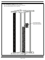
Overhead Cable Openings
•
•
•
•
•
Remove Bezel Insert to allow for overhead cable entry
Cut [8] tabs with wire cutter to open large cable openings - OPTIONAL
Install M10 threaded rod into [6] tapped holes, if desired
[2] 152.4mm x 152.4mm [6” x 6”] openings can be used to route power overhead
PANDUIT COOL BOOTTM products can be used to seal around cables/fiber to prevent hot air recirculation
[6] M10 Threaded Holes
Removable Inserts
Overhead Cable
Opening Bezel
OPTIONAL
[2] 152.4mm x 152.4mm Openings
[6” x 6”]
For Technical Support: www.panduit.com/resources/install_maintain.asp
Page 11 of 28
INSTRUCTIONS CM598G
Cable Management Fingers (SN15F, SN25F)
•
•
Insert tabs of Cable Management Finger into mounting slots of cabinet post
Slide Cable Management Finger inward to lock into place
Cable Managment Finger
-Insert tabs into cabinet post
-Slide inward to lock in place
For Technical Support: www.panduit.com/resources/install_maintain.asp
Page 12 of 28
INSTRUCTIONS CM598G
Dual Hinge Door (Operation)
NOTE: Door is push-to-close. PANDUIT recommends closing handle after opening door and simply push door when closing
Door Function Adjustment (optimize door operation)
•
Remove Dual Hinge Door from cabinet (or open one side at a time)
•
VIEW 1 Loosen [2] Hinge Pin Screws at bottom of cabinet and raise by approximately 6 revolutions (6mm [0.25”])
•
VIEW 2 Lower [2] Hinge Pin Locknuts to bottom of Hinge Pin Post Screw (if nut is not lowered; factory setting of nut is fully-lowered)
•
Reinstall Dual Hinge Door (see page 15)
•
VIEW 3, VIEW 4 Raise [2] Hinge Pin Locknuts until locknuts touch bottom of Dual Hinge Door, then lower locknut 1 revolution
•
VIEW 5 Open each side of Dual Hinge Door and tighten [2] Hinge Pin Screws
•
Close Dual Hinge Door
•
If Dual Hinge Door interferes with Hinge Pin Locknut, lower locknut until there is no interference
VIEW 1
[2] Hinge Pin Screws
(Loosen and raise
6 revolutions)
Ensure BOTH swing handles are in
closed position prior to closing door
6mm
[0.25”]
VIEW 2
[2] Hinge Pin Locknuts
(Lower)
VIEW 3
VIEW 4
Dual Hinge Door
1mm
[0.04”]
[2] Hinge Pin Locknuts
(Raise until locknuts touch
bottom of Dual Hinge Door,
then lower 1 revolution)
VIEW 5
[2] Hinge Pin Screws
(Tighten)
For Technical Support: www.panduit.com/resources/install_maintain.asp
Page 13 of 28
INSTRUCTIONS CM598G
Dual Hinge Door (Removal)
•
•
•
•
Open both swing handles
VIEW 1 While supporting weight of door, pull red finger handle to toggle latch of open side of door to CLOSED position (VIEW 4)
VIEW 2 Remove door from cabinet frame by pushing top of hinged side of door away from cabinet
Lift door off bottom hinge pin
Push Door Away From Cabinet
(ensure that: both swing handles are open and
Latch in CLOSED Position
open side latch is toggled to CLOSED position as
{See VIEW 4)
shown in VIEW 4)
Red Finger Pull
VIEW 1
Swinghandles
VIEW 2
OPEN POSITION
VIEW 3
CLOSED POSITION
VIEW 4
For Technical Support: www.panduit.com/resources/install_maintain.asp
Page 14 of 28
INSTRUCTIONS CM598G
Dual Hinge Door (Installation)
•
•
•
•
•
•
•
Open both swing handles
VIEW 1 Ensure one top latch is OPEN (VIEW 3) and the other is CLOSED (VIEW 4; pull red finger handle to toggle latches)
Lift door (with CLOSED bottom latch) onto bottom hinge pin
VIEW 2 While supporting weight of door, align OPEN top latch with cabinet and push door against cabinet until latched
VIEW 1 Pull red finger handle to toggle top latch of open side to OPEN (VIEW 3) position
Close both swing handles
Close door
Latch in CLOSED Position
{See VIEW 4)
Push Door Towards Cabinet
(ensure that: both swing handles are open
and open side latch is toggled OPEN, as
shown in VIEW 3)
Red Finger Pull
VIEW 1
Swinghandles
OPEN POSITION
CLOSED POSITION
VIEW 2
Lift Pin Bracket
Door Lift Pin
VIEW 3
VIEW 4
For Technical Support: www.panduit.com/resources/install_maintain.asp
Page 15 of 28
INSTRUCTIONS CM598G
Single Hinge Door (Removal and Installation)
•
•
•
•
VIEW 1 Pull down Compression Sleeve at top door hinge
VIEW 1 Pull Single Hinge Door away from cabinet so that Top Hinge Screw fits through cutout of door
VIEW 2 Lift bottom of door off Bottom Hinge Pin
REVERSE STEPS to install Single Hinge Door
Top Hinge Screw
Compression Sleeve (Pull down)
VIEW 1
VIEW 3
Bottom Hinge Pin
VIEW 2
For Technical Support: www.panduit.com/resources/install_maintain.asp
Page 16 of 28
INSTRUCTIONS CM598G
Single Hinge Door (Door Handle Direction Reversal)
•
•
VIEW 1, 2 Remove Top and Bottom Hinge Brackets from current location (remove top hinge screw, if necessary)
VIEW 1, 2 Install Top and Bottom Hinge Brackets on opposite side of cabinet (re-install top hinge screw, if necessary)
Door Handle Reversal (Lay door on a flat surface) - VIEW 3, 4
•
Remove [2] E-clips from Door Handle Cam and exchange positions of Top and Bottom Door Rods
•
Remove Door Handle Backing Plate and rotate position of Door Handle 180º
•
With Door Handle repositioned, secure Door Handle Backing Plate to Door Handle
•
Attach Top and Bottom Door Rods to Door Handle Cam with [2] E-clips (ensure that door rods are behind door rod guides)
•
Remove PANDUIT label and re-attach in correct orientation near top of door
•
Reinstall Single Hinge Door per instructions on Page 16
VIEW 1
VIEW 2
[2] M4 Screws
(use 2.5mm Allen Key)
Top Hinge Bracket
M6 Torx Screw
(use T30 Torx bit)
Bottom Hinge Bracket
[2] E-Clips
[2] Hex Nuts
(use 8mm socket wrench)
Door Rod
Door Handle
(rotate 180º)
Door Rod Guide
Door
Handle
Backing
Plate
VIEW 4
PANDUIT Label
Door Rods
(exchange positions)
Door Rod Guide
For Technical Support: www.panduit.com/resources/install_maintain.asp
Page 17 of 28
VIEW 3
INSTRUCTIONS CM598G
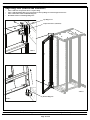
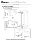
Rear Split Doors (Removal and Installation)
•
•
•
Open Rear Split Doors to approximately 90º
Lift Rear Split Doors up pull doors away from cabinet frame
REVERSE STEPS to install Rear Split Doors
For Technical Support: www.panduit.com/resources/install_maintain.asp
Page 18 of 28
INSTRUCTIONS CM598G
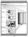
In-Row Side Panel (Removal and Installation)
•
Pull [2] Spring Loaded Hinge Pins to release Front Side Panel from cabinet frame
•
Remove Front Side Panel by pulling panel out of Rear Side Panel channel (towards front of cabinet)
•
Pull [4] Spring Loaded Hinge Pins to release Rear Side Panel from cabinet frame
•
REVERSE STEPS to install In-Row Side Panels
IMPORTANT: Install Rear Side Panel First
In-Row Side Panel Bracket Removal
•
Remove [2] Torx Screws and remove In-Row Side Panel Bracket from cabinet frame
Spring Loaded Hinge Pins
[4] Locations
Rear Side Panel
Spring Loaded Hinge Pin
(Top and Bottom)
Move Finger Pull into
Slot to Lock Hinge Pin
in OPEN position
Rear Side Panel Channel
Rear Side Panel
Front Side Panel
[2] M5 Torx Screws
(use T25 Torx bit)
In-Row Side Panel Bracket
For Technical Support: www.panduit.com/resources/install_maintain.asp
Page 19 of 28
INSTRUCTIONS CM598G
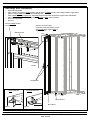
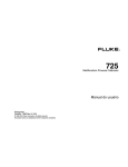
Split/Hinged Side Panels (N21SPH, N22SPH, N51SPH, N52SPH)
•
•
•
VIEW 3 Secure Bottom Support Bracket to cabinet frame with [3] M5 Torx Screws
VIEW 1, 2 Secure Vertical Support Bracket to cabinet frame and bottom support bracket with [1] M5 Torx Screw and [2] Hex Nuts
See Page 21 for Side Panel Installation Instructions
VIEW 1
Vertical Support Bracket
(Top)
[2] Hex Nuts
(use 6mm Socket
Wrench)
[1] M5 Torx Screw
(use T25 Torx bit)
VIEW 2
Vertical Support Bracket
(Bottom)
[3] M5 Torx Screws
(use T25 Torx bit)
Bottom Support Bracket
(Part of bracket cut away to
show detail)
VIEW 3
For Technical Support: www.panduit.com/resources/install_maintain.asp
Page 20 of 28
INSTRUCTIONS CM598G
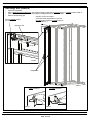
Split/Hinged Side Panels (N21SPH, N22SPH, N51SPH, N52SPH)
•
•
•
•
Open Side Panel to approximately 90º
VIEW 1 Lift Top Hinge Point of Side Panel onto top pin of Vertical Support Bracket
VIEW 2 Lower Bottom Hinge Point of Side Panel onto bottom pin of Vertical Support Bracket
VIEW 3 Close Side Panel and secure top and bottom of Side Panel to cabinet frame with [2] Spring Loaded Hinge Pins
VIEW 1
VIEW 3
Lift Top Hinge Point of Side Panel onto
Top Pin of Vertical Support Bracket
Spring Loaded Hinge Pin
(Top and Bottom)
Hold Hinge Pin Open
VIEW 2
Lower Bottom Hinge Point of Side Panel onto
Bottom Pin of Vertical Support Bracket
For Technical Support: www.panduit.com/resources/install_maintain.asp
Page 21 of 28
INSTRUCTIONS CM598G
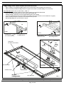
Caster Kit Installation (NCSTR4)
•
•
•
Install [4] Caster Mounting Plates into posts of cabinet (insert bracket into post in an angled position from
above mounting location, rotate bracket, and align bracket with mounting holes)
Install [2] M5 screws into bottom holes of Caster Mounting Plate through cabinet post (as shown below)
Secure [4] Caster Assemblies to Caster Mounting Plates
NOTE: Ensure that fixed casters and swivel casters are paired together at front and rear of cabinet
Caster Mounting Plate
Caster
Mounting
Plate
[2] M5 Hex Head Screw
(use 7mm socket wrench)
Caster
Mounting
Plate
Swivel Caster Assembly
(at rear of cabinet)
Swivel Caster Assembly
(at rear of cabinet)
Fixed Caster Assembly
(at front of cabinet)
[4] M8 Hex Head Screw
(use 13mm socket wrench)
Fixed Caster Assembly
(at front of cabinet)
For Technical Support: www.panduit.com/resources/install_maintain.asp
Page 22 of 28
INSTRUCTIONS CM598G
PDU Bracket Kit Installation
•
•
•
•
•
Install [4] M5 Torx Screws into desired top location of cabinet post, as shown below
Do not tighten screws - Leave a gap between screw and cabinet post for bracket thickness
Place Top PDU Bracket over screw heads and slide up (or down, depending on mounting side of cabinet)
Install Bottom PDU Bracket at desired distance from Top PDU Bracket
Tighten [8] M5 Torx Screws
DO NOT TIGHTEN
(Leave Gap Between
Screw and Cabinet Post)
[4] M5 Torx Screws
(use T25 Torx bit)
PDU Bracket
Top PDU Bracket
PDU Bracket
(installed)
Bottom PDU Bracket
For Technical Support: www.panduit.com/resources/install_maintain.asp
Page 23 of 28
INSTRUCTIONS CM598G
Cabinet Seal Kit Installation
•
•
•
•
Install Foam Seal to the caster seal brackets on the bottom flange.
Install (2) Caster Seal Brackets (1 Left, 1 Right) to the bottom Air dam assembly using (1) M5X0.8 button head torx screw. (do not
tighten)
Install Equipment Seal to the top of the lower front side to side beam and to the bottom of the upper side to side beam, between the
front E-rails.
Install foam seal to the rear flange of the front side to side beam.
*When cabinet is level adjust caster seal brackets to create an air tight seal to the floor. Tighten screws.
Equipment
Seal
Caster Seal
Bracket
M5X0.8 Torx
Screw
Foam Seal
Bottom Foam Seal
For Technical Support: www.panduit.com/resources/install_maintain.asp
Page 24 of 28
INSTRUCTIONS CM598G
Front and Rear Floor Seal Installation
•
Install Floor Seal to front or rear of cabinet frame using (2) M10x20mm bolts. (Flange on floor seal will face
outward away from the cabinet.)
Floor Seal
[2] M10x20mm bolts
For Technical Support: www.panduit.com/resources/install_maintain.asp
Page 25 of 28
INSTRUCTIONS CM598G
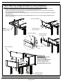
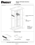
Top of Cabinet Cable Manager Installation
•
•
•
•
•
Disassemble front fascia assemblies (packaged in cabinet) by removing (2) M5x0.8 button head screws (use T25 Torx bit).
Remove (2) M5x0.8 button head screws (use T25 Torx bit) from front and rear of Cable Manager base.
Install vertical walls on front and back of Cable Manager base using (5) M5x0.8 button head Torx screws (use T25 Torx bit).
Re-install screws from previous step to secure to the frame.
Attach front fascia to the front vertical wall by sliding fascia over studs in vertical wall.(see detail view). Tighten with (4) M5x0.8
button head screws (use T25 Torx bit).
Attach rear fascia to the rear vertical wall by sliding fascia over studs in vertical wall (see detail view). Tighten with (4) M5x0.8
button head screws (use T25 Torx bit).
- Remove [4] M5 Torx Screws
(use T25 Torx bit)
[2] Vertical Walls
Rear Fascia
[5] M5 Torx Screws
(use T25 Torx bit)
Front Fascia
[2] Vertical Walls
[4] M5 Torx Screws
(use T25 Torx bit)
Studs
For Technical Support: www.panduit.com/resources/install_maintain.asp
Page 26 of 28
INSTRUCTIONS CM598G
Top of Cabinet Cable Manager Installation (for vertical exhaust ducts)
IMPORTANT - INSTALL VERTICAL EXHAUST DUCT PRIOR TO INSTALLING REAR VERTICAL WALL
•
Disassemble front fascia assemblies (packaged in cabinet) by removing (2) M5x0.8 button head screws (use T25 Torx bit).
•
Remove (2) M5x0.8 button head screws (use T25 Torx bit) from front of Cable Manager base.
•
Install vertical wall on front of Cable Manager base using (5) M5x0.8 button head Torx screws (use T25 Torx bit). Re-install
screws from previous step to secure to the frame.
•
Attach front fascia to the front vertical wall by sliding fascia over studs in vertical wall.(see detail view). Tighten with (4) M5x0.8
button head screws
•
Attach rear vertical wall to the Cable Manger with (4) M5x0.8 button head screws (use T25 Torx bit) from underneath Top of
Cabinet Cable Manager.
Front Vertical Wall
- Remove [2] M5 Torx Screws
(use T25 Torx bit)
[5] M5 Torx Screws
(use T25 Torx bit)
Front Vertical Wall
Rear Vertical Wall
[4] M5 Torx Screws
(use T25 Torx bit)
Studs
IMPORTANT
VERTICAL EXHAUST
DUCT MUST BE
INSTALLED PRIOR TO
INSTALLATION OF
REAR VERTICAL WALL
[4] M5 Torx Screws
(use T25 Torx bit)
For Technical Support: www.panduit.com/resources/install_maintain.asp
Page 27 of 28
INSTRUCTIONS CM598G
This page is left intentionally blank
For Instructions in Local Languages
and Technical Support:
www.panduit.com/resources/install_maintain.asp
www.panduit.com
Page 28 of 28
E-mail:
[email protected]
Phone:
866-405-6654