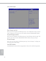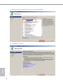
1
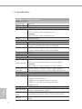
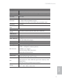
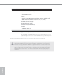
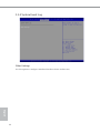
Version 1.0
Published November 2014
Copyright©2014 ASRock Rack Inc. All rights reserved.
Copyright Notice:
No part of this documentation may be reproduced, transcribed, transmitted, or
translated in any language, in any form or by any means, except duplication of
documentation by the purchaser for backup purpose, without written consent of
ASRock Rack Inc.
Products and corporate names appearing in this documentation may or may not
be registered trademarks or copyrights of their respective companies, and are used
only for identiication or explanation and to the owners’ beneit, without intent to
infringe.
Disclaimer:
Speciications and information contained in this documentation are furnished
for informational use only and subject to change without notice, and should not
be constructed as a commitment by ASRock Rack. ASRock Rack assumes no
responsibility for any errors or omissions that may appear in this documentation.
With respect to the contents of this documentation, ASRock Rack does not provide
warranty of any kind, either expressed or implied, including but not limited to
the implied warranties or conditions of merchantability or itness for a particular
purpose.
In no event shall ASRock Rack, its directors, oicers, employees, or agents be liable
for any indirect, special, incidental, or consequential damages (including damages
for loss of proits, loss of business, loss of data, interruption of business and the
like), even if ASRock Rack has been advised of the possibility of such damages
arising from any defect or error in the documentation or product.
his device complies with Part 15 of the FCC Rules. Operation is subject to the following
two conditions:
(1) this device may not cause harmful interference, and
(2) this device must accept any interference received, including interference that
may cause undesired operation.
CALIFORNIA, USA ONLY
he Lithium battery adopted on this motherboard contains Perchlorate, a toxic substance
controlled in Perchlorate Best Management Practices (BMP) regulations passed by the
California Legislature. When you discard the Lithium battery in California, USA, please
follow the related regulations in advance.
“Perchlorate Material-special handling may apply, see www.dtsc.ca.gov/hazardouswaste/
perchlorate”
ASRock Rack’s Website: www.ASRockRack.com
Contact Information
If you need to contact ASRock Rack or want to know more about ASRock Rack,
you’re welcome to visit ASRock Rack’s website at www.ASRockRack.com; or you
may contact your dealer for further information.
ASRock Rack Incorporation
6F., No.37, Sec. 2, Jhongyang S. Rd., Beitou District,
Taipei City 112, Taiwan (R.O.C.)
Contents
Chapter 1 Introduction
1
1.1
Package Contents
1
1.2
Speciications
2
1.3
Unique Features
5
1.4
Motherboard Layout
6
1.5
I/O Panel
10
1.6
Block Diagram
12
Chapter 2 Installation
13
2.1
Screw Holes
13
2.2
Pre-installation Precautions
13
2.3
Installation of Memory Modules (DIMM)
14
2.4
Expansion Slots (PCI Express Slots)
16
2.5
Jumper Setup
17
2.6
Onboard Headers and Connectors
18
2.7
Unit Identiication purpose LED/Switch
23
2.8
Driver Installation Guide
23
Chapter 3 UEFI Setup Utility
24
3.1
Introduction
24
3.1.1
UEFI Menu Bar
24
3.1.2 Navigation Keys
25
3.2
Main Screen
26
3.3
Advanced Screen
27
3.3.1 Easy Raid Installer
28
3.3.2 Storage Coniguration
29
3.3.3 ACPI Coniguration
30
3.3.4 Super IO Coniguration
31
3.4
H/W Monitor Screen (Hardware Health Event Monitoring)
36
3.5
IntelRCSetup
38
3.5.1 Processor Coniguration
39
3.5.2 North Bridge Coniguration
41
3.5.3 South Bridge Chipset Coniguration
42
3.5.4 System Event Log
44
3.6
Server Management
45
3.7
Event Logs
48
3.8
Security Screen
49
3.9
Boot Screen
50
3.10
Exit Screen
52
Chapter 4 Software Support
53
4.1
Install Operating System
53
4.2
Support CD Information
53
4.2.1 Running The Support CD
53
4.2.2 Drivers Menu
53
4.2.3 Utilities Menu
53
4.2.4 Contact Information
53
Chapter 5 Troubleshooting
54
5.1
Troubleshooting Procedures
54
5.2
Technical Support Procedures
56
5.3
Returning Merchandise for Service
56
Chapter 6: Net Framework Installation Guide
57
6.1
57
Installing .Net Framework 3.5.1 (For Server 2008 R2)
C2X50D4I Series
Chapter 1 Introduction
hank you for purchasing ASRock Rack C2X50D4I Series motherboard, a reliable
motherboard produced under ASRock Rack’s consistently stringent quality control.
It delivers excellent performance with robust design conforming to ASRock Rack’s
commitment to quality and endurance.
In this manual, chapter 1 and 2 contains introduction of the motherboard and stepby-step guide to the hardware installation. Chapter 3 and 4 contains the coniguration
guide to BIOS setup and information of the Support CD.
Because the motherboard speciications and the BIOS sotware might be updated, the content of this manual will be subject to change without notice. In case any modiications of
this manual occur, the updated version will be available on ASRock Rack website without
further notice. You may ind the latest memory and CPU support lists on ASRock Rack
website as well. ASRock Rack’s Website: www.ASRockRack.com
If you require technical support related to this motherboard, please visit our website for
speciic information about the model you are using.
http://www.asrockrack.com/support/
1.1 Package Contents
• ASRock Rack C2550D4I / C2750D4I / C2750D4I+ Motherboard
(Mini-ITX Form Factor: 6.7-in x 6.7-in, 17.0 cm x 17.0 cm)
• Support CD
• User Manual
• 6 x Serial ATA (SATA) Cables (Optional)
• 1 x I/O Shield
English
If any items are missing or appear damaged, contact your authorized dealer.
1
1.2 Speciications
C2550D4I / C2750D4I / C2750D4I+
MB Physical Status
Form Factor
Mini-ITX
Dimension
6.7'' x 6.7'' (17.0 cm x 17.0 cm)
Processor System
CPU
C2750D4I / C2750D4I+:
Intel® Octa Core Avoton C2750 Processor
C2550D4I:
Intel® Octa Core Avoton C2550 Processor
FCBGA1283 SOC
English
Socket
System Memory
Max. Capacity
64GB DDR3 ECC UDIMM
Socket
- 4 x 240-pin DDR3 DIMM slots
- Support up to 64GB DDR3 ECC and UDIMM
Type
- Dual Channel DDR3 memory technology
- Supports DDR3 1600/1333 ECC and UDIMM
Voltage
1.5V, 1.35V
Expansion Slot
1 slot (x8 mode)
PCIe 2.0 x 8
Storage
C2750D4I / C2750D4I+:
Intel® C2750 : 2 x SATA3 6.0 Gb/s, 4 x SATA2 3.0 Gb/s
SATA Controller
C2550D4I:
Intel® C2550 : 2 x SATA3 6.0 Gb/s, 4 x SATA2 3.0 Gb/s
Additional SATA - Marvell SE9172: 2 x SATA3 6.0 Gb/s, support RAID 0, 1
Controller
- Marvell SE9230: 4 x SATA3 6.0 Gb/s, support RAID 0, 1, 10
Ethernet
Interface
Gigabit LAN 10/100/1000 Mb/s
LAN Controller - 2 x Intel® i210
- Supports Wake-On-LAN
- Supports Energy Eicient Ethernet 802.3az
- Supports Dual LAN with Teaming function
- Supports PXE
Management
ASPEED AST2300 : IPMI (Intelligent Platform Management
BMC Controller
Interface) 2.0 with iKVM support
IPMI Dedicated
1 x Realtek RTL8211E for dedicated management GLAN
GLAN
- Watch Dog
Features
- NMI
2
C2X50D4I Series
Gracphics
Controller
VRAM
Output
Rear Panel I/O
VGA Port
USB 2.0 Port
LAN Port
Serial Port
ASPEED AST2300
DDR3 16MB
Supports D-Sub with max. resolution up to 1920x1200 @ 60Hz
1 x D-Sub
2
- 2 x RJ45 Gigabit Ethernet LAN ports
- 1 x RJ45 Dedicated IPMI LAN port
- LAN Ports with LED (ACT/LINK LED and SPEED LED)
1 (COM1)
UID Button/UID
1
LED
Internal Connector
Auxiliary Panel
1 (includes location button & LED, front LAN LED)
Header
IPMB Header
1
Fan Header
ATX Power
6 x 4-pin
1 (24-pin)
1 (support 1 via headers or 2 via headers controlled by USB_
SEL1 and USB_SEL2 jumper)
1
USB 2.0 Header
Front Panel
System BIOS
BIOS Type
English
64Mb AMI UEFI Legal BIOS
- Plug and Play (PnP)
- ACPI 1.1 Compliance Wake Up Events
BIOS Features
- SMBIOS 2.3.1 Support
- DRAM Voltage Multi-adjustment
- ASRock Rack Instant Flash
Hardware Monitor
- CPU Temperature Sensing
Temperature
- Motherboard Temperature Sensing
- CPU/Rear/Front Fan Tachometer
- CPU Quiet Fan (Allow CPU Fan Speed Auto-Adjust by CPU
Fan
Temperature)
- CPU/Rear/Front Fan Multi-Speed Control
Voltage Monitoring: +12V, +5V, +3.3V, CPU Vcore, DRAM,
Voltage
+1.1V, +1.0V, +BAT, 3VSB, 5VSB
3
Support OS
OS
Microsot® Windows®
- Server 2008 R2 SP1 (64 bit)
- Server 2012 (64 bit)
Linux®
- CentOS 6.4/5.10 (x32 and x64) (only support AHCI mode)
- SUSE Enterprise Linux Server 11 SP1 (32 / 64 bit)
- FreeBSD 9.1 (32 / 64 bit)
- Fedora Core 19 (64 bit)
- Ubuntu 12.04/12.10 (64 bit)
Virtual:
- VMWare ESXi 5.5
Environment
Temperature
Operation temperature: 10°C ~ 35°C / Non operation
temperature: -40°C ~ 70°C
*For C2750D4I / C2550D4I motherboard, please install a CPU fan when the
airlow throught the heat sink is below 2 CFM(Cubic Feet per Minute) for better ventilation.
* For detailed product information, please visit our website: http://www.asrockrack.com
Since Intel® Edisonville platform does not support RSTe feature, it is decided by OS inbox
driver behavior. he Avoton processor integrated I/O’s SATA2/3 driver is used inbox not
Intel®. So according to Windows® 2008 R2 OS operation behaviors, it needs to take about
~60sec refresh timer when users unplug SATA device. You have to go in manually to detect
the drive and recognize it. In other words, the operation system will quickly response the
SATA plug in/out status about ~10sec when users install the RSTe driver if the platform
supports it.
English
4
C2X50D4I Series
1.3 Unique Features
ASRock Instant Flash is a BIOS lash utility embedded in Flash ROM. his convenient BIOS update tool allows you to update system BIOS without entering operating
systems irst like MS-DOS or Windows®. With this utility, you can press the <F6> key
during the POST or the <F2> key to enter into the BIOS setup menu to access ASRock
Rack Instant Flash. Just launch this tool and save the new BIOS ile to your USB lash
drive, loppy disk or hard drive, then you can update your BIOS only in a few clicks
without preparing an additional loppy diskette or other complicated lash utility.
Please be noted that the USB lash drive or hard drive must use FAT32/16/12 ile
English
system.
5
1.4 Motherboard Layout
C2750D4I
1
17.0cm (6.7 in)
ATXPWR1
COM1
VGA1
DDR3_A2 (64 bit, 240-pin module)
2
DDR3_A1 (64 bit, 240-pin module)
3
Top:
IPMI
LAN
REAR_FAN2
REAR_FAN1
4
LAN2 LAN1
CPU_FAN2
CPU_FAN1
64Mb
BIOS
UID_SW_LED1
17.0cm (6.7 in)
USB 2.0
T: USB_0
B: USB_1
5
6
SATA_0
DDR3_B1 (64 bit, 240-pin module)
32
7
31
DDR3_B2 (64 bit, 240-pin module)
SATA_1
SATA_2
SATA3_M0
CMOS
Battery
8
RoHS
30
29
SATA_3
SATA_4
9
SATA3_M1
SATAIII_M0
CLRCMOS1
28
Super
I/O
27
10
11
12
SATA_5
26
SATAIII_M1
1
1
SATAIII_M2
BMC_SMB_1
IPMB_1
USB_SEL1
1
1
BMC_SMB_2
English
6
PANEL1
HDLED RESET
15
TPMS1
AUX_PANEL1
1
1
SATAIII_M3
BMC_SMB_3
PCIE1
FRNT_FAN1
1
C2750D4I
25
USB_SEL2
USB_2-3
1
BMC
ROM
14
1
1
1
23
22
16
FRNT_FAN2
NMI_BTN1
24
21
13
PLED PWRBTN
20 19 18
17
C2X50D4I Series
C2750D4I+
1
17.0cm (6.7 in)
ATXPWR1
COM1
VGA1
DDR3_A2 (64 bit, 240-pin module)
2
DDR3_A1 (64 bit, 240-pin module)
3
Top:
IPMI
LAN
REAR_FAN2
REAR_FAN1
4
LAN2 LAN1
CPU_FAN2
CPU_FAN1
17.0cm (6.7 in)
USB 2.0
T: USB_0
B: USB_1
64Mb
BIOS
UID_SW_LED1
5
6
SATA_0
DDR3_B1 (64 bit, 240-pin module)
32
7
31
DDR3_B2 (64 bit, 240-pin module)
SATA_1
SATA_2
SATA3_M0
CMOS
Battery
8
RoHS
30
29
SATA_3
SATA_4
9
SATA3_M1
SATAIII_M0
CLRCMOS1
28
Super
I/O
27
10
11
12
SATA_5
SATAIII_M1
1
1
SATAIII_M2
BMC_SMB_1
IPMB_1
USB_SEL1
1
1
BMC_SMB_2
PANEL1
HDLED RESET
15
TPMS1
AUX_PANEL1
1
1
SATAIII_M3
BMC_SMB_3
PCIE1
FRNT_FAN1
1
C2750D4I+
25
USB_SEL2
USB_2-3
1
BMC
ROM
14
1
1
1
13
PLED PWRBTN
16
FRNT_FAN2
NMI_BTN1
24
23
22
21
20 19 18
17
English
26
7
C2550D4I
1
17.0cm (6.7 in)
ATXPWR1
COM1
VGA1
DDR3_A2 (64 bit, 240-pin module)
2
DDR3_A1 (64 bit, 240-pin module)
3
Top:
IPMI
LAN
REAR_FAN2
REAR_FAN1
4
LAN2 LAN1
CPU_FAN2
CPU_FAN1
64Mb
BIOS
UID_SW_LED1
17.0cm (6.7 in)
USB 2.0
T: USB_0
B: USB_1
5
6
SATA_0
DDR3_B1 (64 bit, 240-pin module)
32
7
31
DDR3_B2 (64 bit, 240-pin module)
SATA_1
SATA_2
SATA3_M0
CMOS
Battery
8
RoHS
30
29
SATA_3
SATA_4
9
SATA3_M1
SATAIII_M0
CLRCMOS1
28
Super
I/O
27
10
11
12
SATA_5
26
SATAIII_M1
1
1
SATAIII_M2
BMC_SMB_1
IPMB_1
USB_SEL1
1
BMC_SMB_2
English
8
PANEL1
HDLED RESET
15
TPMS1
AUX_PANEL1
1
1
SATAIII_M3
BMC_SMB_3
PCIE1
FRNT_FAN1
1
C2550D4I
25
USB_SEL2
USB_2-3
1
BMC
ROM
14
1
1
1
1
23
22
16
FRNT_FAN2
NMI_BTN1
24
21
13
PLED PWRBTN
20 19 18
17
C2X50D4I Series
Description
1
ATX Power Connector (ATXPWR1)
2
2 x 240-pin DDR3 DIMM Slots (DDR3_A1, DDR3_A2)
3
Rear Fan Connector (REAR_FAN1)
4
Rear Fan Connector (REAR_FAN2)
5
CPU Fan Connector (CPU_FAN1)
6
CPU Fan Connector (CPU_FAN2)
7
2 x 240-pin DDR3 DIMM Slots (DDR3_B1, DDR3_B2)
8
SATA3 Connector (SATA3_M0, White)
9
SATA3 Connector (SATA3_M1, White)
10
USB Selection Jumper (USB_SEL1)
11
SATA3 Connector (SATAIII_M0, White)
12
SATA3 Connector (SATAIII_M1, White)
13
System Panel Header (PANEL1)
14
SATA3 Connector (SATAIII_M2, White)
15
SATA3 Connector (SATAIII_M3, White)
16
Front Fan Connector (FRNT_FAN2)
17
Front Fan Connector (FRNT_FAN1)
18
TPM Header (TPMS1)
19
USB Selection Jumper (USB_SEL2)
20
BMC SMB Header (BMC_SMB3)
21
Non Maskable Interrupt Button (NMI_BTN1)
22
USB 2.0 Header (USB_2-3)
23
Auxiliary Panel Header (AUX_PANEL1)
24
Intelligent Platform Management Bus header (IPMB_1)
25
BMC SMB Header (BMC_SMB2)
26
BMC SMB Header (BMC_SMB1)
27
SATA2 Connector (SATA_5, Blue)
28
SATA2 Connector (SATA_4, Blue)
29
SATA2 Connector (SATA_3, Blue)
30
SATA2 Connector (SATA_2, Blue)
31
SATA3 Connector (SATA_1, White)
32
SATA3 Connector (SATA_0, White)
English
No.
9
1.5 I/O Panel
C2550D4I / C2750D4I / C2750D4I+
1
3
5
2
4
6
7
No. Description
No. Description
1
Serial Port (COM1)
5
2
D-Sub Port (VGA1)
6
LAN RJ-45 Port (LAN2)**
3
Dedicated IPMI LAN Port*
7
UID Switch/LED (UID_SW_LED1)
4
USB 2.0 Ports (USB_0-1)
LAN RJ-45 Port (LAN1)**
LAN Port LED Indications
*here are two LED next to the LAN port. Please refer to the table below for the LAN port
LED indications.
ACT/LINK LED
SPEED LED
LAN Port
Dedicated IPMI LAN Port LED Indications
English
10
Activity / Link LED
Speed LED
Status
Description
Status
Description
Of
Blinking
On
No Link
Data Activity
100Mbps connection
Of
Orange
Green
10Mbps connection
100Mbps connection
1Gbps connection
C2X50D4I Series
**here are two LEDs on each LAN port. Please refer to the table below for the LAN port
LED indications.
ACT/LINK LED
SPEED LED
LAN Port
Activity / Link LED
Speed LED
Status
Description
Status
Description
Of
Blinking
On
No Link
Data Activity
100Mbps connection
Of
Of
Green
10Mbps connection
100Mbps connection
1Gbps connection
English
LAN Port (LAN1, LAN2) LED Indications
11
English
12
1.6 Block Diagram
128-bit Dual-Channel Memory x 4 Slots
SATA3_M0
SATA3_M1
PCI-E X8 SLOT
PCIE x1
INTEL I210
PCIE x1
INTEL I210
PCIE x1
DDR3 1066/1333/1600
Channel B
DDR3 1066/1333/1600
PCI_E BUS
100MHz
Marvell 9172
Channel A
Intel Processor
SATA BUS
100MHz
SATA_4
SATA_2
SATA_5
SATA_3
SATA_0
SATA_1
PEX8608
USB2_0
USB2_1
Avoton
BMC AST2300
PCIE x1
SATAIII_M0
SATAIII_M1
SATAIII_M2
1283 pin
PCIE x2
Marvell 9230
100MHz
SATAIII_M3
SPI FLASH
64Mb
SPI
TPM
33MHz
LPC BUS
SIO
Nuvoton NCT5573D
USB2_2
C2X50D4I Series
Chapter 2 Installation
This is a Mini-ITX form factor (6.7'' x 6.7'', 17.0 cm x 17.0 cm) motherboard. Before
you install the motherboard, study the coniguration of your chassis to ensure that the
motherboard its into it.
Make sure to unplug the power cord before installing or removing the motherboard. Failure
to do so may cause physical injuries to you and damages to motherboard components.
2.1 Screw Holes
Place screws into the holes indicated by circles to secure the motherboard to the chassis.
Do not over-tighten the screws! Doing so may damage the motherboard.
2.2 Pre-installation Precautions
Take note of the following precautions before you install motherboard components or
change any motherboard settings.
1. Unplug the power cord from the wall socket before touching any components.
2. To avoid damaging the motherboard’s components due to static electricity, NEVER
place your motherboard directly on the carpet or the like. Also remember to use a
grounded wrist strap or touch a safety grounded object before you handle the components.
3. Hold components by the edges and do not touch the ICs.
4. Whenever you uninstall any component, place it on a grounded anti-static pad or in
the bag that comes with the component.
5. When placing screws into the screw holes to secure the motherboard to the chassis,
please do not over-tighten the screws! Doing so may damage the motherboard.
English
Before you install or remove any component, ensure that the power is switched of or the
power cord is detached from the power supply. Failure to do so may cause severe damage to
the motherboard, peripherals, and/or components.
13
2.3 Installation of Memory Modules (DIMM)
his motherboard provides four 240-pin DDR3 (Double Data Rate 3) DIMM slots, and
supports Dual Channel Memory Technology.
1. For dual channel coniguration, you always need to install identical (the same brand,
speed, size and chip-type) DDR3 DIMM pairs.
2. It is unable to activate Dual Channel Memory Technology with only one or three memory
module installed.
3. It is not allowed to install a DDR or DDR2 memory module into a DDR3 slot; otherwise,
this motherboard and DIMM may be damaged.
4. Please install the memory module on DDR3_A1 for the irst priority.
Dual Channel Memory Coniguration
Priority
DDR3_A1
(Blue)
1
Populated
2
Populated
DDR3_A2
(White)
DDR3_B1
(Blue)
DDR3_B2
(White)
Populated
Populated
Populated
Populated
he DIMM only its in one correct orientation. It will cause permanent damage to the
motherboard and the DIMM if you force the DIMM into the slot at incorrect orientation.
English
14
C2X50D4I Series
1
2
English
3
15
2.4 Expansion Slots (PCI Express Slots)
here is 1 PCI Express slots on this motherboard.
PCIE slot:
PCIE1 (PCIE 2.0 x8 slot) is used for PCI Express x8 lane width graphics cards.
Installing an expansion card
Step 1.
Step 2.
Step 3.
Step 4.
Step 5.
Step 6.
English
16
Before installing an expansion card, please make sure that the power
supply is switched of or the power cord is unplugged. Please read the
documentation of the expansion card and make necessary hardware
settings for the card before you start the installation.
Remove the system unit cover (if your motherboard is already installed
in a chassis).
Remove the bracket facing the slot that you intend to use. Keep the
screws for later use.
Align the card connector with the slot and press irmly until the card is
completely seated on the slot.
Fasten the card to the chassis with screws.
Replace the system cover.
C2X50D4I Series
2.5 Jumper Setup
he illustration shows how jumpers are setup. When the jumper cap is placed on
the pins, the jumper is “Short”. If no jumper cap is placed on the pins, the jumper
is “Open”. he illustration shows a 3-pin jumper whose pin1 and pin2 are “Short”
when a jumper cap is placed on these 2 pins.
USB Selection Jumper
(3-pin USB_SEL1)
(No. 10)
(3-pin USB_SEL2)
(No. 19)
Support:
Rear USB 2.0 ports x 1
Front USB header x 2
English
Support:
Rear USB 2.0 ports x 2
Front USB header x 1
(Default)
17
2.6 Onboard Headers and Connectors
Onboard headers and connectors are NOT jumpers. Do NOT place jumper caps over these
headers and connectors. Placing jumper caps over the headers and connectors will cause
permanent damage to the motherboard.
*You can see p.6 or p.7 for motherboard layout.
Serial ATA3 Connectors
(SATA_0: No. 32)
(SATA_1: No. 31)
(SATA3_M0: No. 8)
(SATA3_M1: No. 9)
(SATAIII_M0: No. 11)
(SATAIII_M1: No. 12)
(SATAIII_M2: No. 14)
(SATAIII_M3: No. 15)
SATA_0
SATA3_M0
SATA_1
SATA3_M1
SATAIII_M0
hese eight Serial ATA3
(SATA3) connectors support
SATA data cables for internal
storage devices. he current
SATA3 interface allows up to
6.0 Gb/s data transfer rate.
SATAIII_M1
SATAIII_M2
SATAIII_M3
Serial ATA2 Connectors
(SATA_2: No. 30)
(SATA_3: No. 29)
(SATA_4: No. 28)
(SATA_5: No. 27)
SATA_2
SATA_3
SATA_4
hese four Serial ATA2
(SATA2) connectors support
SATA data cables for internal
storage devices. he current
SATA2 interface allows up to
3.0 Gb/s data transfer rate.
SATA_5
USB_PWR
-B
+B
USB 2.0 Header
(9-pin USB_2-3)
(No. 22)
GND
DUMMY
1
English
GND
+A
-A
USB_PWR
18
Besides two default USB 2.0
ports on the I/O panel, there
is one USB 2.0 header on this
motherboard. Each USB 2.0
header can support two USB
2.0 ports.
GND
LAD0
SERIRQ#
GND
+3V
S_PWRDWN#
LAD2
LAD1
LAD3
SMB_CLK_MAIN
SMB_DATA_MAIN
GND
FRAME
TPM Header
(17-pin TPMS1)
(No. 18)
PCICLK
C2X50D4I Series
System Panel Header
(9-pin PANEL1)
(No. 13)
PLED+
PLEDPWRBTN#
GND
1
GND
+3VSB
PCIRST#
1
his connector supports Trusted Platform Module (TPM)
system, which can securely
store keys, digital certiicates,
passwords, and data. A TPM
system also helps enhance
network security, protects
digital identities, and ensures
platform integrity.
his header accommodates
several system front panel
functions.
GND
RESET#
GND
HDLEDHDLED+
PWRBTN (Power Switch):
Connect to the power switch on the chassis front panel. You may conigure the way to turn
of your system using the power switch.
RESET (Reset Switch):
Connect to the reset switch on the chassis front panel. Press the reset switch to restart the
computer if the computer freezes and fails to perform a normal restart.
PLED (System Power LED):
Connect to the power status indicator on the chassis front panel. he LED is on when the
system is operating. he LED is of when the system is in powered of (S5).
HDLED (Hard Drive Activity LED):
Connect to the hard drive activity LED on the chassis front panel. he LED is on when the
hard drive is reading or writing data.
English
he front panel design may difer by chassis. A front panel module mainly consists of power
switch, reset switch, power LED, hard drive activity LED, speaker and etc. When connecting your chassis front panel module to this header, make sure the wire assignments and the
pin assignments are matched correctly.
19
LED_PWR
LAN2_LINK
LOCATORLED2-
LOCATORLED2+
LAN1_LINK
LED_PWR
LOCATORBTN#
GND
+5VSB
LOCATORLED1-
GND
12C_4_DATA#
B
LOCATORLED1+
NC
A
12C_4_CLK#
Auxiliary Panel Header
(18-pin AUX_PANEL1)
(No. 14)
his header supports multiple
functions on the front panel,
including front panel SMB,
internet status indicator.
NC
GND
+5VSB
1
C
A. Front panel SMBus connecting pin (6-1 pin FPSMB)
his header allows you to connect SMBus (System Management Bus) equipment. It can
be used for communication between peripheral equipment in the system, which has slower
transmission rates, and power management equipment.
B. Internet status indicator (2-pin LAN1_LED, LAN2_LED)
hese two 2-pin headers allow you to use the Gigabit internet indicator cable to connect
to the LAN status indicator. When this indicator lickers, it means that the internet is properly connected.
C. Locator LED (6-pin LOCATOR)
his header is for the locator switch and LED on the front panel.
Front and Rear
Fan Connectors
(4-pin FRNT_FAN1)
(No. 17)
(4-pin FRNT_FAN2)
(No. 16)
(4-pin REAR_FAN1)
No. 3)
(4-pin REAR_FAN2)
(No. 4)
English
20
GND
+12V
FAN_SPEED
FAN_SPEED_CONTROL
GND
+12V
FAN_SPEED
FAN_SPEED_CONTROL
GND
+12V
FAN_SPEED
FAN_SPEED_CONTROL
GND
+12V
FAN_SPEED
FAN_SPEED_CONTROL
Please connect the fan cables to
the fan connectors and match
the black wire to the ground
pin. All fans supports Fan
Control.
C2X50D4I Series
CPU Fan Connectors
(4-pin CPU_FAN1)
(No. 5)
1
(4-pin CPU_FAN2)
(No. 6)
1
GND
2
+12V
3
FAN_SPEED
4
FAN_SPEED_CONTROL
GND
+12V
2
3
4
Please connect the CPU fan
cable to the connector and
match the black wire to the
ground pin.
hough this motherboard
provides a 4-Pin CPU fan
(Quiet Fan) connector, 3-Pin
CPU fans can still work
successfully even without the
fan speed control function.
If you plan to connect a
3-Pin CPU fan to the CPU
fan connector on this
motherboard, please connect
it to Pin 1-3.
*For more details, please refer to the
FAN_SPEED
FAN_SPEED_CONTROL
Cooler QVL list on the ASRock Rack
website.
1
Intelligent Platform
Management Bus header
(4-pin IPMB_1)
(No. 24)
12
Please connect an ATX power
supply to this connector.
24 hough this motherboard
provides a 24-pin ATX power
connector, it can still work if
you adopt a traditional 20pin ATX power supply. To use
a 20-pin ATX power supply,
please plug your power supply
along Pin 1 and Pin 13.
13
GND
No connect
IPMB_SCL
IPMB_SDA
his 4-pin connector is used
to provide a cabled baseboard
or front panel connection for
value added features and 3rdparty add-in cards, such as
Emergency Management cards,
that provide management
features using the IPMB.
English
ATX Power Connector
(24-pin ATXPWR1)
No. 1)
21
Non Maskable Interrupt
Button Header
(2-pin NMI_BTN1)
(see p.13 or 15, No. 21)
BMC SMB Headers
(5-pin BMC_SMB_1)
(No. 26)
(5-pin BMC_SMB_2)
(No. 25)
(5-pin BMC_SMB_3)
(No. 20)
English
22
POWER
1
CONTROL
Please connect a NMI device to
this header.
his header is used for the SM
BUS devices.
C2X50D4I Series
2.7 Unit Identiication purpose LED/Switch
With the UID button, You are able to locate the server you’re working on from behind
a rack of servers.
Unit Identiication
purpose LED/Switch
(UID_SW_LED1)
When the UID button on the
front or rear panel is pressed,
the front/rear UID blue LED
indicator will be turned on.
Press the UID button again to
turn of the indicator.
2.8 Driver Installation Guide
English
To install the drivers to your system, please insert the support CD to your optical
drive irst. hen, the drivers compatible to your system can be auto-detected and listed
on the support CD driver page. Please follow the order from top to bottom to install
those required drivers. herefore, the drivers you install can work properly.
23
Chapter 3 UEFI Setup Utility
3.1 Introduction
his section explains how to use the UEFI SETUP UTILITY to conigure your system. he
UEFI chip on the motherboard stores the UEFI SETUP UTILITY. You may run the UEFI
SETUP UTILITY when you start up the computer. Please press <F2> or <Del> during the
Power-On-Self-Test (POST) to enter the UEFI SETUP UTILITY; otherwise, POST will
continue with its test routines.
If you wish to enter the UEFI SETUP UTILITY ater POST, restart the system by pressing
<Ctrl> + <Alt> + <Delete>, or by pressing the reset button on the system chassis. You may
also restart by turning the system of and then back on.
Because the UEFI sotware is constantly being updated, the following UEFI setup screens
and descriptions are for reference purpose only, and they may not exactly match what you
see on your screen.
3.1.1 UEFI Menu Bar
he top of the screen has a menu bar with the following selections:
Item
Description
Main
To set up the system time/date information
Advanced
To set up the advanced UEFI features
H/W Monitor
To display current hardware status
IntelRCSetup
For Intel CPU and chipset settings
Server Mgmt
To manage the server
Event Logs
For event log coniguration
Security
To set up the security features
Boot
To set up the default system device to locate and load the
Operating System
Exit
To exit the current screen or the UEFI SETUP UTILITY
English
Use < > key or < > key to choose among the selections on the menu bar, and
then press <Enter> to get into the sub screen.
24
C2X50D4I Series
3.1.2 Navigation Keys
Please check the following table for the function description of each navigation key.
Function Description
/
Moves cursor let or right to select Screens
/
Moves cursor up or down to select items
+ / -
To change option for the selected items
<Tab>
Switch to next function
<Enter>
To bring up the selected screen
<PGUP>
Go to the previous page
<PGDN>
Go to the next page
<HOME>
Go to the top of the screen
<END>
Go to the bottom of the screen
<F1>
To display the General Help Screen
<F7>
Discard changes and exit the UEFI SETUP UTILITY
<F9>
Load optimal default values for all the settings
<F10>
Save changes and exit the UEFI SETUP UTILITY
<F12>
Print screen
<ESC>
Jump to the Exit Screen or exit the current screen
English
Navigation Key(s)
25
3.2 Main Screen
Once you enter the UEFI SETUP UTILITY, the Main screen will appear and display the
system overview. he Main screen provides system overview information and allows you
to set the system time and date.
English
26
C2X50D4I Series
3.3 Advanced Screen
In this section, you may set the conigurations for the following items: Easy RAID Installer, Storage Coniguration, ACPI Coniguration, Super IO Coniguration, Serial Port Console Redirection, PCI Subsystem Settings, PLX 8608 Coniguration, Voltage and Instant
Flash.
Setting wrong values in this section may cause the system to malfunction.
Instant Flash
English
Instant Flash is a UEFI lash utility embedded in Flash ROM. his convenient UEFI update
tool allows you to update system UEFI without entering operating systems irst like MSDOS or Windows®. Just save the new UEFI ile to your USB lash drive, loppy disk or hard
drive and launch this tool, then you can update your UEFI only in a few clicks without preparing an additional loppy diskette or other complicated lash utility. Please be noted that
the USB lash drive or hard drive must use FAT32/16/12 ile system. If you execute Instant
Flash utility, the utility will show the UEFI iles and their respective information. Select
the proper UEFI ile to update your UEFI, and reboot your system ater the UEFI update
process is completed.
27
3.3.1 Easy Raid Installer
Easy RAID Installer can help you to copy the RAID driver from a support CD to your USB
storage device. Ater copying the RAID driver to your USB storage device, please change
“SATA Mode” to “RAID”, then you can start installing the OS in RAID mode.
English
28
C2X50D4I Series
3.3.2 Storage Coniguration
Hard Disk S.M.A.R.T.
Use this item to enable or disable the S.M.A.R.T. (Self-Monitoring, Analysis, and Reporting
Technology) feature.
Marvell 9230 SATA3_M0~M3 Operation
This item is for Marvell 9230 SATA3_M0~M3 ports. Use this to select Marvell SATA3
mode. Coniguration options: [Enabled] and [Disabled]. he default value is [Enabled].
Bootable Marvell 9230 SATAIII
Use this to enable or disable Marvell SATA Boot ROM.
Marvell 9172 SATA3_M0_M1 Operation
his item is for Marvell 9172 SATA3_M0 and M1 ports. Use this to select Marvell SATA3
mode. Coniguration options: [Disabled], [IDE Mode], [AHCI Mode] and [RAID Mode].
he default value is [AHCI Mode].
Bootable Marvell 9172 SATA3
English
Use this to enable or disable Marvell SATA Boot ROM.
We recommend to use Intel® SATA ports (SATA_0 to SATA_5 ports) for your bootable
devices. his will minimum your boot time and get the best performance. But if you still
want to boot from Marvell SATA3 controller, you can still enable this in UEFI.
29
3.3.3 ACPI Coniguration
ACPI HPET Table
Enable the High Precision Event Timer for better performance.
PCIE Devices Power On
Use this item to enable or disable PCIE devices to turn on the system from the power-sotof mode.
RTC Alarm Power On
Use this item to enable or disable RTC (Real Time Clock) to power on the system.
English
30
C2X50D4I Series
3.3.4 Super IO Coniguration
Deep Sleep
Use this to conigure Deep Sleep. he default value is [Disabled].
Serial Port 1 Coniguration
Use this item to conigure the onboard serial port 1.
SOL Coniguration
English
Use this item to conigure the onboard serial port 2.
31
3.3.5 Serial Port Console Redirection
Console Redirection
Use this option to enable or disable Console Redirection.
Console Redirection Settings
Use this option to conigure Console Redirection Settings,
English
32
C2X50D4I Series
3.3.6 PCI Subsystem Settings
Above 4G Decoding
English
Use this option to enable or disable 64bit capable devices to be decoded in above 4G
address space (only if system supports 64bit PCI decoding).
33
3.3.7 PLX 8608 Coniguration
Primary Graphics Adapter
his allows you to select [Onboard] or [PCI Express] as the boot graphic adapter priority.
he default value is [PCI Express].
Onboard VGA
his allows you to enable or disable the Onboard VGA feature.
Onboard LAN1
his allows you to enable or disable the Onboard LAN1 feature.
Onboard LAN2
his allows you to enable or disable the Onboard LAN2 feature.
English
34
C2X50D4I Series
3.3.8 Voltage
DRAM Voltage
English
Use this to select DRAM Voltage. he default value is [Auto].
35
3.4 H/W Monitor Screen (Hardware Health Event Monitoring)
In this section, it allows you to monitor the status of the hardware on your system, including the parameters of the CPU temperature, motherboard temperature and the critical
voltage.
CPU_FAN1 Setting
his allows you to set the speed of CPU fan 1. he default value is [Smart Fan].
CPU_FAN2 Setting
his allows you to set the speed of CPU fan 2. he default value is [Smart Fan].
REAR_FAN1 Setting
his allows you to set the speed of REAR Fan 1. he default valu is [Smart Fan].
REAR_FAN2 Setting
his allows you to set the speed of REAR Fan 2. he default value is [Smart Fan].
FRNT_FAN1 Setting
English
his allows you to set the speed of FRNT Fan 1. he default value is [Smart Fan].
FRNT_FAN2 Setting
his allows you to set the speed of FRNT Fan 2. he default value is [Smart Fan].
36
C2X50D4I Series
Watch Dog Timer
English
his allows you to enable or disable the Watch Dog Timer. he default value is [Disabled].
37
3.5 IntelRCSetup
In this section, you may set the conigurations for the following items: Processor Coniguration, North Bridge Chipset Coniguration, South Bridge Chipset Coniguration and
System Event Log.
English
38
C2X50D4I Series
3.5.1 Processor Coniguration
Intel SpeedStep Technology
Intel SpeedStep technology is Intel’s new power saving technology. Processors can switch
between multiple frequencies and voltage points to enable power saving. he default value
is [Enabled]. Coniguration options: [Enabled] and [Disabled]. his item will be hidden if
the current CPU does not support Intel SpeedStep technology.
Please note that enabling this function may reduce CPU voltage and lead to system stability
or compatibility issues with some power supplies. Please set this item to [Disabled] if above
issues occur.
CPU C State
Use this to enable or disable the support of CPU C State.
No-Execute Memory Protection
English
Processors with No-Execution Memory Protection Technology may prevent certain classes
of malicious bufer overlow attacks.
Intel Virtualization Technology
When this option is set to [Enabled], a VMM (Virtual Machine Architecture) can utilize
the additional hardware capabilities provided by Vanderpool Technology. his option will
be hidden if the installed CPU does not support Intel Virtualization Technology.
39
Intel Turbo Boost Technology
Use this item to enable or disable Intel Turbo Boost Mode Technology. Turbo Boost Mode
allows processor cores to run faster than marked frequency in speciic conditions. he
default value is [Enabled].
Active Processor Cores
Use this item to select the number of cores to enable in each processor package. he default
value is [All].
English
40
C2X50D4I Series
3.5.2 North Bridge Coniguration
Fast Boot
Use this item to enable to disable fast boot which skips memory training and attempts to
boot using last known good coniguration.
DRAM Frequency
If [Auto] is selected, the motherboard will detect the memory module(s) inserted and
assign the appropriate frequency automatically.
ECC Support
English
Use this item to enable or disable DDR ECC Support.
41
3.5.3 South Bridge Chipset Coniguration
Restore on AC/Power Loss
Select the power state ater a power failure. If [Power Of] is selected, the power will remain
of when the power recovers. If [Power On] is selected, the system will start to boot up
when the power recovers.
SATA Coniguration
English
42
C2X50D4I Series
SATA 2 Controller / SATA 3 Controller
Use this item to enable or disable SATA Controller.
SATA Mode Selection
Use this to select SATA mode. Configuration options: [Disabled], [IDE Mode], [AHCI
Mode] and [RAID Mode]. he default value is [AHCI Mode].
AHCI (Advanced Host Controller Interface) supports NCQ and other new features that will
improve SATA disk performance but IDE mode does not have these advantages.
SATA Link Power Management
Use this item to conigure SATA Aggressive Link Power Management.
SATA_x
Depending on how many SATA ports you have, you will see SATA_x (x means number)
listed on the screen, with its status indicated as SATA device [(Model Name)] or [Not
Detected].
SATA_x Rx Setting
Adjust SATA DTLE DATA Values (0-15).
Spin Up
If enabled for any of ports, Staggered Spin Up will be performed and only the drives which
have this option enabled will spin up at boot. Otherwise all drives spin up at boot.
External Device
Use this item to enable SATA safe removal notiications. Please note that the SATA device
will be downgraded to SATA2.
Hot Plug
English
Designates this port as Hot Plugglable.
43
3.5.4 System Event Log
Whea Settings
Use this option to conigure Windows Hardware Error Architecture.
English
44
C2X50D4I Series
3.6 Server Management
Wait For BMC
Wait For BMC response for speciied time out. In PILOTII, BMC starts at the same time
when BIOS starts during AC power ON. It takes around 30 seconds to initialize Host to
BMC interfaces.
System Event Log
Enter to conigure System Event Logging features during boot.
BMC Network Coniguration
Press <Enter> to conigure BMC Network parameters.
Coniguration Address Source
Select to conigure BMC network parameters statically or dynamically(by BIOS or BMC).
Coniguration options: [Unspeciied], [Static], and [Dynamic].
English
Unspeciied: BMC network parameters are conigured by BMC itself.
Static: Manually enter the IP Address, Subnet Mask and Gateway Address in the BIOS for
BMC LAN channel coniguration.
Dynamic: IP address, Subnet Mask and Gateway Address are automatically assigned by
the network's DHCP server.
45
To configure BMC network parameters using the BIOS setup, select either [Static] or
[Dynamic] option.
To conigure BMC network parameters using the BMC web interface, select [Unspeciied]
option.
When [Dynamic] or [Static] is selected, do NOT modify the BMC network settings on the
IPMI web page.
BMC Mac Backup Tool
Use this to restore BMC Mac from the backup.
he default login information for the IPMI web interface is:
Username: admin
Password: admin
English
46
C2X50D4I Series
Please refer to the table below for the LAN interface mapping to check the MAC address
through either BIOS or Web interface.
BMC LAN Interface Mapping Table
I/O Panel
BIOS Menu
IPMI Web Page
LAN1 Port (NCSI)
Lan Channel 1
eth0
IPMI Port
Lan Channel 2
eth1
BIOS Menu
Server Mgmt
tab
(Example image only)
IPMI Web Page
Coniguration
> Network
Settings
(Example image only)
English
For more instructions on how to set up remote control environment and use the IPMI management platform, please refer to the IPMI Coniguration User Guide or go to the Support
website at: http://www.asrockrack.com/support/ipmi.asp
47
3.7 Event Logs
Change Smbios Event Log Settings
his allows you to conigure the Smbios Event Log Settings.
View Smbois Event Log
his allows you to view the Smbios Event Log.
English
48
C2X50D4I Series
3.8 Security Screen
In this section, you may set or change the supervisor/user password for the system. For the
user password, you may also clear it.
Supervisor Password
Set or change the password for the administrator account. Only the administrator
has authority to change the settings in the UEFI Setup Utility. Leave it blank and
press enter to remove the password.
User Password
English
Set or change the password for the user account. Users are unable to change the
settings in the UEFI Setup Utility. Leave it blank and press enter to remove the
password.
49
3.9 Boot Screen
In this section, it will display the available devices on your system for you to conigure the
boot settings and the boot priority.
Boot Option #1
Use this item to set the system boot order.
Setup Prompt Timeout
his shows the number of seconds to wait for setup activation key.
Bootup Num-Lock
If this item is set to [On], it will automatically activate the Numeric Lock function ater
boot-up.
PCI ROM Priority
Use this item to adjust PCI ROM Priority. he default value is [LegacyROM]
Full Screen Logo
English
Use this item to enable or disable OEM Logo. he default value is [Enabled].
AddOn ROM Display
Use this option to adjust AddOn ROM Display. If you enable the option “Full Screen Logo”
but you want to see the AddOn ROM information when the system boots, please select
50
C2X50D4I Series
[Enabled]. Coniguration options: [Enabled] and [Disabled]. he default value is [Enabled].
Boot From Onboard LAN
Use this item to enable or disable the Boot From Onboard LAN feature.
CSM Parameters
Use this option to conigure the parameters of OpROM execution, boot options ilter, etc.
Boot Option Filter
Use this option to control what devices system can boot to. Coniguration options: [UEFI
and Legacy], [Legacy only] and [UEFI only].
Launch Storage OpROM Policy
English
Select UEFI only to run those that support UEFI option ROM only. Select [Legacy only] to
run those that support legacy option ROM only.
51
3.10 Exit Screen
Save Changes and Exit
When you select this option, the following message “Save coniguration changes and exit
setup?” will pop-out. Select [Yes] to save the changes and exit the UEFI SETUP UTILITY.
Discard Changes and Exit
When you select this option, the following message “Discard changes and exit setup?” will
pop-out. Select [Yes] to exit the UEFI SETUP UTILITY without saving any changes.
Discard Changes
When you select this option, the following message “Discard changes?” will pop-out.
Select [Yes] to discard all changes.
Load UEFI Defaults
Load UEFI default values for all the setup questions. F9 key can be used for this operation.
English
52
C2X50D4I Series
Chapter 4 Software Support
4.1 Install Operating System
his motherboard supports Microsot® Windows® Server 2008 R2 SP1 (64 bit) / 2012 (64
bit) / Linux compliant. Because motherboard settings and hardware options vary, use the
setup procedures in this chapter for general reference only. Refer your OS documentation
for more information.
*Please download the Intel ® SATA Floppy Image driver from the ASRock Rack’s website (www.asrockrack.com)
to your USB drive or simply install the SATA driver from the Support CD while installing OS in SATA RAID
mode.
4.2 Support CD Information
he Support CD that came with the motherboard contains necessary drivers and useful
utilities that enhance the motherboard’s features.
4.2.1 Running The Support CD
To begin using the support CD, insert the CD into your CD-ROM drive. The CD
automatically displays the Main Menu if “AUTORUN” is enabled in your computer. If the
Main Menu does not appear automatically, locate and double click on the ile “ASRSetup.
exe” from the root folder in the Support CD to display the menu.
4.2.2 Drivers Menu
The Drivers Menu shows the available device’s drivers if the system detects installed
devices. Please install the necessary drivers to activate the devices.
4.2.3 Utilities Menu
he Utilities Menu shows the application sotwares that the motherboard supports. Click
on a speciic item then follow the installation wizard to install it.
4.2.4 Contact Information
English
If you need to contact ASRock Rack or want to know more about ASRock Rack, welcome
to visit ASRock Rack’s website at http://www.ASRockRack.com; or you may contact your
dealer for further information.
53
Chapter 5 Troubleshooting
5.1 Troubleshooting Procedures
Follow the procedures below to troubleshoot your system.
Always unplug the power cord before adding, removing or changing any hardware components. Failure to do so may cause physical injuries to you and damages to motherboard
components.
1. Disconnect the power cable and check whether the PWR LED is of.
2. Unplug all cables, connectors and remove all add-on cards from the motherboard.
Make sure that the jumpers are set to default settings.
3. Conirm that there are no short circuits between the motherboard and the chassis.
4. Install a CPU and fan on the motherboard, then connect the chassis speaker and power
LED.
If there is no power...
1.
2.
3.
4.
Conirm that there are no short circuits between the motherboard and the chassis.
Make sure that the jumpers are set to default settings.
Check the settings of the 115V/230V switch on the power supply.
Verify if the battery on the motherboard provides ~3VDC. Install a new battery if it
does not.
If there is no video...
1. Try replugging the monitor cables and power cord.
2. Check for memory errors.
If there are memory errors...
English
1. Verify that the DIMM modules are properly seated in the slots.
2. Use recommended DDR3 1600/1333/1066 non ECC, unbufered DIMMs.
3. If you have installed more than one DIMM modules, they should be identical with the
same brand, speed, size and chip-type.
4. Try inserting diferent DIMM modules into diferent slots to identify faulty ones.
5. Check the settings of the 115V/230V switch on the power supply.
54
C2X50D4I Series
Unable to save system setup conigurations...
1. Verify if the battery on the motherboard provides ~3VDC. Install a new battery if it
does not.
2. Conirm whether your power supply provides adaquate and stable power.
Other problems...
English
1. Try searching keywords related to your problem on ASRock Rack’s FAQ page:
http://www.asrockrack.com/support
55
5.2 Technical Support Procedures
If you have tried the troubleshooting procedures mentioned above and the problems
are still unsolved, please contact ASRock Rack’s technical support with the following
information:
1.
2.
3.
4.
Your contact information
Model name, BIOS version and problem type
System coniguration
Problem description
You may contact ASRock Rack’s technical support at:
http://www.asrockrack.com/support/tsd.asp
5.3 Returning Merchandise for Service
For warranty service, the receipt or a copy of your invoice marked with the date of
purchase is required. By calling your vendor or going to our RMA website (http://event.
asrockrack.com/tsd.asp) you may obtain a Returned Merchandise Authorization (RMA)
number.
The RMA number should be displayed on the outside of the shipping carton which is
mailed prepaid or hand-carried when you return the motherboard to the manufacturer.
Shipping and handling charges will be applied for all orders that must be mailed when
service is complete.
This warranty does not cover damages incurred in shipping or from failure due to
alteration, misuse, abuse or improper maintenance of products.
Contact your distributor irst for any product related problems during the warranty period.
English
56
C2X50D4I Series
Chapter 6: Net Framework Installation Guide
To let Intel® RSTe works properly, it is required to install Net Framework. Please follow the
steps below to enable “.Net Framework” feature on Microsot® Windows® Server 2008 R2.
6.1 Installing .Net Framework 3.5.1 (For Server 2008 R2)
1. Double-click the Server Manager icon in the Windows system tray.
English
2. Click Add Features in the right hand pane.
57
3. Check the box next to .Net Framework 3.5.1 and then click Next.
4. Click Next to continue.
English
58
5. Click Install to start installing .Net Framework 3.5.1.
6. Ater the installation completes, click Close.
59