1
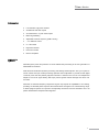
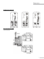
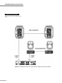
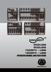
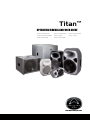
Titan™
OPERATING MANUAL AND USER GUIDE
Titan™ 8 Passive
Titan™ 8 Active MKII
Titan™ Sub A12
Titan™ 12 Passive
Titan™ 12D
Titan™ Sub A15
Titan™ 15 Passive
Titan™ 15D www.wharfedalepro.com
OPERATING MANUAL AND USER GUIDE
IMPORTANT WARNINGS & SAFETY INSTRUCTIONS
1. Read these instructions
2. Follow all instructions
3. Keep these instructions
4. Heed all warnings
5. Do not use this apparatus near water
6. Clean only with dry cloth.
7. Do not block any ventilation openings. Install in accordance with the manufacturer’s
instructions.
8. Do not install near any heat sources such as radiators, heat registers, stoves, or other
apparatus (including amplifiers) that produce heat.
9. Do not defeat the safety purpose of the polarised or grounding plug. A polarised plug has two
blades with one wider than the other. A grounding plug has two blades and a third grounding
prong. The wide blade or the third prong is provided for your safety. If the provided plug does
not fit into your outlet, consult an electrician for replacement of the obsolete outlet.
10. Protect the power cord from being walked on or pinched particularly at the plugs, convenience
receptacles, and at the point where they exit from the apparatus.
11. Only use attachments/accessories specified by the manufacturer.
12. Use only with a cart, stand, tripod, bracket, or table specified by the manufacturer, or sold with
the apparatus. When a cart or rack is used, use caution when moving the cart and apparatus
combination to avoid injury from tip-over.
13. Unplug the apparatus during lightning storms or when unused for long periods of time.
14. Refer all servicing to qualified personnel. Servicing is required when the apparatus has been
damaged in any way including but not limited to power supply cord or plug damage, liquid
ingress, foreign objects in the chassis, exposure to rain/moisture or impact damage. In addition
the unit must be serviced when you experience any abnormal operation.
15. CAUTION: These servicing instructions are for use by qualified service personnel only. To
reduce the risk of electric shock, do not attempt to perform any servicing other than that
contained in the operating instructions unless you are qualified to do so. In addition opening the
casing will result in your warranty becoming null and void.
16. Do not install this apparatus in a confined space such as a book case or similar unit. Good
ventilation should be maintained around the apparatus and any vents, air-inlets or fans should
not be obstructed by objects such as paper, table-cloths, curtains etc.
17. WARNING: To reduce the risk of fire or electric shock, do not expose the apparatus to rain or
moisture. The apparatus should not be exposed to dripping or splashing and objects filled with
liquids, such as vases, should not be placed on the apparatus.
18. WARNING: The mains plug/appliance coupler is used as a disconnect device, the disconnect
device shall remain readily operable.
1
Titan™ Series
ATTENTION: RISQUE DE CHOC ELECTRIQUE-NE PAS OUVRIR
19. - This lightning flash with arrowhead symbol within an equilateral triangle is intended to alert the
user to the presence of non-insulated “dangerous voltage” within the product’s enclosure that
may be of sufficient magnitude to constitute a risk of electric shock.
- Warning: To reduce the risk of electric shock, do not remove the cover (or back) as there are
no user-serviceable parts inside. Refer servicing to qualified personnel.
- The exclamation point within an equilateral triangle is intended to alert the user to the
presence of important operating and maintenance instructions in the literature accompanying
the appliance.
20.
(Protective earthing terminal) The apparatus should be connected to a mains socket outlet
with a protective earthing connection.
21. Correct Disposal of this product. This marking indicates that this product should not be
disposed with other household wastes throughout the EU. To prevent possible harm to the
environment or human health from uncontrolled waste disposal, recycle it responsibly to
promote the sustainable reuse of material resources. To return your used device, please use
local return and collection systems or contact the retailer where the product was purchased.
They can take this product for safe environmentally friendly recycling.
2
OPERATING MANUAL AND USER GUIDE
TABLE OF CONTENTS
1..........................................Important Warnings & Safety Instructions
2..........................................Important Safety Information Powered Products
4..........................................Introduction / About the Titan™ Series
4..........................................Titan series overview
5..........................................Features
6..........................................Qubit
7..........................................Setting up / Speaker Placement
7..........................................Connections / Wiring - Passive 8..........................................Rear Panel Layout - Passive
8..........................................Connection Diagram - Passive 11...........................................Rear Panel Layout - Active
14..........................................Connection Diagram - Active
15..........................................Rear Panel Layout - Sub A12
16..........................................Connection Diagram - Sub A12
18..........................................Rear Panel Layout - Sub A15
19..........................................Connection Diagram - Sub A15
21..........................................Specifications - Titan™ Passive
22..........................................Specifications - Titan™ Active
24..........................................Specifications - Titan™ Subwoofers
25..........................................Dimensional Drawings - Titan™ 8 / 12
26..........................................Dimensional Drawings - Titan™ 15 / 8A MKII
27..........................................Dimensional Drawings - Titan™ 12D / 15D
28..........................................Dimensional Drawings - Titan™ Sub A12 / A15
29…………………………..…Warranty
3
Titan™ Series
INTRODUCTION
Wharfedale Pro Titan™ Series is the result of many years of experience in the use, design and
manufacturing of professional loudspeaker products. We take great pride in engineering and
building every Wharfedale Pro loudspeaker and wish to thank you for entrusting us with your sound.
From the time Gilbert Briggs built his first loudspeaker in 1932, to the present, Wharfedale
Loudspeakers have maintained the same standard of quality in components, workmanship and
performance. Wharfedale are one of the few present day manufacturers that design, engineer and
build all of our own transducers.
Please take a few minutes to read this manual completely in order to ensure that you get the most
out of your Titan™ Series Loudspeaker system.
TITAN™ SERIES OVERVIEW
The Titan Series are powerful, accurate, high quality loudspeaker systems with low distortion
that are designed to deliver oustanding performance at a cost effective price point. An Elliptical
Wave Guide (EWG) is perfectly matched to the custom designed HF drivers and provides smooth
dispersion in both the horizontal and vertical planes.
The road tough, gas-assist injection moulded polypropylene enclosures are ultra lightweight
and include rubberised handles and cable management to make Titan the most user-friendly
portable speaker on the market. Threaded rigging points mean that Titan is equally suited to flown
applications; a comprehensive range of Wharfedale Pro wall mounting options are also available as
optional extras.
Active models feature rear panel power LED’s and a throat mounted LED to make you aware of AC
power supply from both the front and rear of the unit. Active models also feature a horn LED defeat
switch for less obtrusive aesthetics in applications such as conferencing and A/V presentations.
The BRO™ (Bass Response Optimizer) circuit on the 12D and 15D models helps counteract loss of
bass at low levels, similar to a loudness switch on home HiFi amplifiers. In addition our "D" models
feature Qubit™ 24-bit 192kHz DSP Processing.
4
OPERATING MANUAL AND USER GUIDE
FEATURES
Titan Passive
♦ 2-way full range loudspeakers
♦
Low distortion, high power moisture proof woofers
♦ HF compression drivers
♦
90° x 60° Elliptical Wave Guide (EWG)
♦ DTF™ Dynamic Thermal Filament HF protection
♦
Lightweight, high strength gas-assist injection moulded polypropylene enclosures
♦ Ergonomic rubberised handles
♦
Integral lockable 35mm (1⅜”) pole mount socket
♦ M6 / M8 rigging points
♦
Speakon™ and ¼” jack inputs
♦
Bi-amplified full range loudspeakers
♦
Low distortion, high power moisture proof woofers
Titan Active
♦ HF compression drivers
♦
Qubit™ 24-bit 192kHz DSP processing ♦
Independent LF & HF adaptive dynamics and signal limiting
♦
Per channel volume controls (Master only on 8A MKII)
♦
2 Band EQ
♦
90° x 60° elliptical Wave Guide (EWG)
♦
BRO™ Bass Response Optimizer (12D & 15D only)
♦
Horn LED defeat switch
♦
Balanced XLR output for parallel wiring
♦
XLR / ¼” jack combo inputs
♦ Mic / line level input selector
♦
2 mixable inputs (12D & 15D only)
♦
Stereo RCA inputs (12D & 15D only)
♦
Lightweight, high strength gas-assist injection moulded polypropylene enclosures
♦ Ergonomic rubberized handles
♦
Integral lockable 35mm (1⅜”) pole mount socket
♦ M6 / M8 rigging points
♦ IEC AC receptacle
5
Titan™ Series
Subwoofer
♦
Low distortion, high power woofers
♦
2x balanced XLR HPF outputs
♦
2x summed XLR / ¼” jack combo inputs
♦
Built in signal limiting
♦
Adjustable crossover frequency (SUB 12A only)
♦ -∞to +6dB trim control
♦ 0° / 180° switch
♦ Ergonomic handles
♦ Pole mount socket
♦ IEC AC receptacle
QUBIT™
Qubit brings the power and precision of 24-bit 192kHz DSP processing to the next generation of
Wharfedale Pro Products.
With advanced multi-band dynamic processing and filtering Qubit helps fine tune your system to
sound natural and open. Qubit processing optimises the loudspeaker to provide smooth digital
crossover points that are perfectly aligned. Protection is offered in the form of true independent
adaptive LF and HF signal limiting that helps protect against thermal damage and driver over
excursion.
Qubit has an extended frequency response that goes way beyond the capabilities of our hearing,
providing an extended phase response that remains linear throughout our natural hearing range.
A Qubit equipped system can reproduce exceptionally natural and accurate transients due to its
phase characteristics and perfect time alignment.
6
OPERATING MANUAL AND USER GUIDE
SETTING UP
1. Ensure the speakers power switch is in the off position (Active models only)
2. Set the level controls to minimum (Fully anticlockwise) (Active models only)
3. Set the EQ controls to 0dB (Active models only)
4. Select mic/line input (Active models only)
5. Connect all signal cables
6. Connect the power cable (Active models only)
7. Switch on source equipment, ensuring that the master level is at minimum
8. Switch on the Titan Loudspeaker (Active models only)
9. Raise the level control on the Titan (Active models only) or external amplifier
10. If the limit LED illuminates lower the level control, if more level is required you will need more
speakers. Occasional flashes are acceptable. (Active models only)
11. When powering down your system ensure that the level control (Active models only) has been
lowered to minimum before switching off the power
SPEAKER PLACEMENT
The well behaved dispersion characteristics of the Titan series make speaker placement quick and
simple.
As with all full range loudspeakers it is recommended to place a Titan above the head level of the
audience, as the human body can absorb a huge amount of high frequency energy. Placing the
loudspeaker enclosure higher up also helps improve coverage for more even levels over a greater
audience area.
Tripod speaker stands, pole mounts, Wall brackets and rigging hardware can be used to elevate the
Titan loudspeaker. Always ensure that any accessories that are used are capable of safely elevating
the loudspeaker as incorrect rigging can be dangerous and even fatal. Please refer to the important
safety warnings section for more guidelines on rigging and suspending.
Always place your microphones outside the coverage of your front of house speakers to reduce the
risk of feedback.
7
Titan™ Series
Titan™ REAR PANEL LAYOUT
CONNECTION DIAGRAM #1
Titan two channel setup
8
OPERATING MANUAL AND USER GUIDE
CONNECTION DIAGRAM # 2
Titan mono front of house+stage monitor
setup
NOTE: This configuration represents a 4 ohm load to each output channel of the amplifier
9 Titan™ Series
CONNECTION DIAGRAM # 3
USING THE Titan WITH A PASSIVE
SUBWOOFER
CONNECTION DIAGRAM # 4
USING THE Titan™ 8/12/15 IN A
BI-AMP SYSTEM
10
OPERATING MANUAL AND USER GUIDE
Titan™ 8A MKII / Titan™ 12D / Titan™ 15D
The Loop / Mix Switch
The LOOP/MIX switch allows you to control the signal content going to the XLR OUTPUT jack. In the “LOOP”
mode, this switch routes the signal of INPUT B to the line level XLR OUTPUT jack, bypassing the EQ section
and volume control. When in the MIX mode, this switch routes the combined (or “mixed”) signals of both INPUT
A and INPUT B to the line level XLR OUTPUT jack. This signal can then be sent to additional powered speakers
or powered subwoofers.
8A MKII - REAR PANEL FEATURES
11
Titan™ Series
Titan™ 12D/15D REAR PANEL LAYOUT
1
3
2
7
8
4
5
6
9
10
12
11
13
14
12
OPERATING MANUAL AND USER GUIDE
TITAN™ 8A MKII/12D/15D REAR PANEL FEATURES
1. Heat Sink: The heat sink allows for dissipation of heat built up from the amplifier via air cooling at the rear
of the enclosure. (Titan 8A MKII and 15D only)
2. VOLUME for INPUT A and INPUT B: These knobs control the level of each input channel (Controls the
master volume on the Titan 8A MKII)
3. HI and LOW EQ (equalization) controls: These knobs control the equalization of the overall output
signal providing +/- 10dB of gain for each band.
4. Remote Control: This Pheonix connector can be used to control the volume with an applied voltage.
5. 90Hz Monitor Filter switch: Used to reduce bass buildup due to half space loading.
6. Horn LED defeat switch: Switches off the horn power LED for discrete applications.
7. RCA L / R (Left and Right) input jacks: These jacks allow input of a stereo signal (left and right). The
signal is actively combined or “summed” providing a mono signal to the amplifier.
8. GAIN selection switch: This switch selects the proper gain structure for INPUT A. If a microphone is
connected to INPUT A, use mic mode (up). If the signal source is anything other than a microphone (playback
device, keyboard or mixer output, for instance) use the line mode (down) .
9 & 10. POWER ON / OFF switch, POWER ´ON´ indicator LED and LIMIT indicator LED: The
switch: turns the power on and off. The bracketed LED to the left of the POWER switch illuminates when the
power switch is in the´ON´ position. The LIMIT LED illuminates when the signal limiter is limiting the level of
the signal to prevent distortion and overload. 11. Output source “LOOP / MIX” switch: In the “LOOP” mode, this switch routes the signal of INPUT B to
the line level XLR OUTPUT jack, bypassing the EQ section and volume control. When in the MIX mode, this
switch routes the combined (or “mixed”) signals of both INPUT A and INPUT B to the line level XLR OUTPUT
jack.
12. XLR / ¼” COMBO input jacks for INPUT A and INPUT B: These convenient jacks allow XLR or ¼”
balanced input connections to INPUT A and INPUT B
13. POWER cord receptacle: This is a receptacle for a standard IEC, three prong, grounded AC electrical
connection cord. Be sure that you are plugging into the correct source voltage that matches what is indicated
just below the power cord jack.
14.XLR line level OUTPUT jack: This jack provides a balanced line level output for connection to additional
Titan™ ACTIVES, powered subwoofers or amplifiers.
13
Titan™ Series
Titan™12D / 15D CONNECTION DIAGRAM # 1
Basic microphone / playback hookup
Titan™12D / 15D CONNECTION DIAGRAM # 2
Connecting two Titan™ ACTIVE speakers together
14
OPERATING MANUAL AND USER GUIDE
TITAN™ SUB A12 REAR PANEL FEATURES
1. HEAT SINK
Cooling fins for amplifier. Do not obstruct.
2. VOLUME CONTROL
Adjusts the volume.
3. INPUT L
Balanced line level input via a XLR/ ¼” combo connector.
4. INPUT R
Balanced line level input via a XLR/ ¼” combo connector.
5. OUTPUT R
Balanced male XLR connector provides output HIGHPASS signal.
6. OUTPUT L
Balanced male XLR connector provides output HIGHPASS signal.
7. POWER SOCKET
This is the connection for the IEC AC power connector.
8. LIMIT LED
LED indicator illuminates when the signal limiting function is activated.
POWER LED
LED indicator illuminates when the unit is powered up.
9. POWER SWITCH
Turns the power on and off to the subwoofer amplifier module.
10.PHASE SWITCH
Selects the polarity of the signal being sent to the subwoofer.
0° selects the signal polarity as it appears at the input.
The 180° selection inverts the polarity of the signal.
11.CROSSOVER
15
FREQUENCY
CONTROL
Adjustable 80Hz/100Hz/120Hz/150Hz/180Hz/200Hz.
Titan™ Series
Titan™ Sub-A12 CONNECTION DIAGRAM # 1
TWO CHANNEL SYSTEM WITH HIGHPASS OUTPUT
16
OPERATING MANUAL AND USER GUIDE
Titan™ Sub-A12 CONNECTION DIAGRAM # 2
USING TWO Titan™ Sub-A12 WITH
TWO POWER SPEAKERS
17
Titan™ Series
Titan™ Sub-A15 - REAR PANEL FEATURES
1. INPUT A - Balanced line level input via a XLR / ¼” combo connection.
2. OUTPUT A - Balanced male XLR connection provides “THRU” or HIGHPASS signal (depending on switch
setting).
3. SPEAKER LEVEL INPUT - Allows for connection of an external amplifier to use the Titan™ Sub-A15 as a
passive subwoofer.
NOTE: Disconnect the power cord when using the Titan™ Sub-A15 in this mode.
4. INPUT B - Balanced line level input via a XLR / ¼” combo connection.
5. OUTPUT B - Balanced male XLR connection provides output “THRU” or HIGHPASS signal (depending on
switch setting).
6. HEATSINK - Cooling fins for amplifier. Do not obstruct.
7. VOLUME CONTROL - Adjusts volume level of the subwoofer. 8. THRU / HIGHPASS SWITCH - Selects the signal type that is routed to the OUTPUT jacks, “THRU” sends the
unprocessed signal to the outputs. “HIGHPASS” filters the signal at 100Hz to the outputs.
9. PHASE SWITCH - Selects the polarity of the signal being sent to the subwoofer. 0° selects the signal polarity
as it appears at the input. The “180°” selection inverts the phase of the signal.
10.LIMIT LED - LED indicator illuminates when the singal limiting function is activated.
11.POWER LED - LED indicator illuminates when the unit is powered up.
12.POWER SOCKET - This is the connection for the IEC AC power connector.
13.POWER SWITCH - Turns the power on and off to the subwoofer amplifier module.
OUTPUT A
3
SPEAKER
LEVEL INPUT
5
(B A L A N C E D )
I
0
I
I
IMAX
WWW.WHARFEDALEPRO.COM
VOLUME
SPEAKER
LEVEL IN
(100Hz)
HIGHPASS
INPUT B
B
OUTPUT B
I
8
_
THRU
RISK
0°
180°
PHASE
CAUTION
O F ELECTR IC SHO CK
D O N O T O PE N
!
WARNING: SHOCK HAZARD DO NOT OPEN
AVIS: RISQUE DE CHOC ELECTRIQUE -NE PAS OUVRIR
LIMIT
N 2082
ON
(B A L A N C ED )
(B A L A N C ED )
INPUT
OUTPUT
7
I
I
4
OUTPUT
I
2
INPUT
(B A L A N C E D )
A
I
INPUT A
6
VOLUME
CONTROL
I
1
HEATSINK
OFF
POWER
AC 220-240V~50Hz 400W
FUSE T4AL250V
THRU/HIGHPASS
SWITCH
PHASE SWITCH
8
9
LIMIT LED
10
POWER LED
11
POWER SOCKET
12
POWER SWITCH
13
SERIALNUMBER
18
OPERATING MANUAL AND USER GUIDE
Titan™ Sub-A12 CONNECTION DIAGRAM # 1
TWO CHANNEL SYSTEM WITH
HIGHPASS OUTPUT
NOTE: This same connection configuration can be used with OUTPUT A and B used in a fullrange mode when the THRU/HIGHPASS switch is in the "THRU" (up) position.
19
Titan™ Series
CONNECTION DIAGRAM # 2
USING TWO Titan™ Sub-A15's WITH
TWO POWERED SPEAKERS
20
OPERATING MANUAL AND USER GUIDE
SPECIFICATIONS - Titan™ PASSIVE SERIES
Titan™ 8
Titan™ 12
Titan™ 15
Loudspeaker Type:
8" 2-way
12" 2-way
15" 2-way
Frequency Response (+/–3dB):
70 - 20kHz
55 - 20kHz
50 - 20kHz
Sensitivity (1W@1M):
96dB
98dB
97dB
Peak SPL:
124dB
128dB
129dB
HF Coverage (H x V):
90˚ x 60˚
90˚ x 60˚
90˚ x 60˚
System Impedance:
8 ohm
8 ohm
8 ohm
Continuous:
150W
250W
400W
Music:
300W
500
800W
Peak:
600W
1000
1600W
Size:
203mm/ 8"
305mm/ 12"
381mm/ 15"
Coil Size:
38.86mm / 1.53"
64.26mm / 2.5"
75mm / 3.0"
HF DRIVER/ HORN
Compression Driver
Compression Driver
Compression Driver
Coil Size:
25mm/1"
44mm/1.75"
51mm/ 2.0"
Exit Size:
30mm/1.2"
25mm/1"
25mm/1"
Diaphragm Material:
Cloth
Titanium
Titanium
HF Driver Protection:
Bulb
DTF™ Dynamic Thermal Filament
DTF™ Dynamic Thermal Filament
Long-Throw EQ Compensation:
N/A
3dB boost (long-throw) / Flat
N/A
POWER (WATTS)
LF DRIVER
(near-field)
Horn Type:
EWG™ - Elliptical Waveguide
EWG™ - Elliptical Waveguide
EWG™ - Elliptical Waveguide
Throat Size:
25mm/1"
25mm/1"
25mm/1"
2-way 2.4KHz / Linkwitz-Riley
2-way 2.2KHz / Linkwitz-Riley
2-way 1.8KHz / Linkwitz-Riley
Shape/ Material:
Trapezoidal/ Polypropylene
Trapezoidal/ Polypropylene
Trapezoidal/ Polypropylene
Rigging:
(8) M6 threaded rigging points
(10) M8 threaded rigging points
(10) M8 threaded rigging points
+ (4) M6 threaded rigging points
+ (4) M8 threaded rigging points
+ (4) M8 threaded rigging points
on bottom in Omnimount®
on bottom in Omnimount®
on bottom in Omnimount®
30.0-type footprint + Speaker pole-
60.0-type footprint + Speaker
60.0-type footprint + Speaker
mount receptacle with lock screw
pole-mount receptacle with lock
pole-mount receptacle with lock
+ 1 built-in carry handle + Optional
screw + Optional wall-mount
screw + Optional wall-mount
wall-mount bracket + (Optional
bracket + (Optional dual-unit
bracket + (Optional dual unit
dual-unit array speaker stand
array speaker stand hardware)
array speaker stand hardware)
CROSSOVER
Type/Frequency/Filter:
ENCLOSURE
hardware)
COLOURS
Grey or Black or White
Grey or Black or White
Grey or Black or White
OUTPUT CONNECTORS
2 x 1/4" jacks + 2 x NL4
2 x 1/4" jacks + 2 x NL4
2 x 1/4" jacks + 2 x NL4
Weight:
5.5kg / 12.1lbs
12kg / 26.4lbs
22kg / 48.4lbs
Dimensions (H x W x D):
396 x 266 x 221mm/
556 x 384 x 312mm/
708.3 x 477.8 x 401.77mm/
15.59" x 10.47" x 8.7"
21.88" x 15.1" x 12.3"
27.9" x 18.8" x 15.8
DIMENSIONS/WEIGHTS
21
Titan™ Series
SPECIFICATIONS - Titan™ ACTIVE SERIES
Titan™ 8 ACTIVE MK II
Titan™ 12 D
Titan™ 15 D
System Type
Active 8” 2-way Bi-Amplified
Active 12” 2-way Bi -Amplified
Active 15” 2-way Bi -Amplified
Frequency Response (+/-3dB)
70-20kHz
55-20kHz
50-20kHz
Low Frequency Driver (mm/in.)
205mm / 8”
305mm / 12”
381mm / 15”
High Frequency Driver
Compression Driver
Titanium Compression Driver
Titanium Compression Driver
Exit Size (mm / inches)
30mm / 1.2”
25mm / 1"
25mm / 1"
Dispersion (H x V)
90° x 60°
90° x 60°
90° x 60°
Amplifiers
Low Frequency (Class D)
Rated 150W continuous, 300W Peak
Rated 250W continuous, 500W Peak
Rated 350W continuous, 700W Peak
High Frequency (Class D)
Rated 30W continuous, 60W Peak
Rated 50W continuous, 100W Peak
Rated 70W continuous, 140W Peak
Electronic Crossover:
24dB per octave Linkwitz-Riley
24dB/octave Linkwitz-Riley
24dB/octave Linkwitz-Riley
Crossover Frequency
2.4kHz
2.3kHz
1.8kHz
Equalization:
High (±10dB) 10kHz Shelving
High (±10dB) 10kHz Shelving
High (±10dB) 10kHz Shelving
Low (±10dB) 100Hz Shelving
Low (±5dB) 100Hz Shelving
Low (±10dB) 100Hz Shelving
30Hz, Second - order filter
30Hz, Second - order filter
30Hz, Second - order filter
Power On
Power switch on / off mute
Power switch on / off mute
Power switch on / off mute
Thermal
Amplifier shutdown, auto reset
Amplifier shutdown, auto reset
Amplifier shutdown, auto reset
Low Line Voltage Shut Down
< 80VAC
60% Nominal line voltage
60% Nominal line voltage
Driver Protection
Independent LF and HF limiters
Independent LF and HF limiters
Independent LF and HF limiters
DC Protection
Yes
Yes
Yes
Short Protection
Yes
Yes
Yes
Clip Limiter:
Turns on approx 150W output
Turns on approx 250W output
Turns on approx 350W output
Limiter Indicator
Red LED
Red LED
Red LED
Power Indicator
Green LED
Green LED
Green LED
Subsonic Filter
Amplifier Protection
22
OPERATING MANUAL AND USER GUIDE
SPECIFICATIONS - Titan™ ACTIVE (Con't)
Titan™ 8 ACTIVE MKII
Titan™ 12 D
Titan™ 15 D
Switchable balanced mic or line
Switchable balanced mic or line
Switchable balanced mic or line
level input
level input
level input
Mic: -47dBu (-49.2dBv or
Mic: -40dBu (-42.2dBv or
Mic: -40dBu (-42.2dBv or
3.4mVrms)
7.75mVrms)
7.75mVrms)
Line: 0dBu (-2.2dBv or 0.775Vrms)
Line: 0dBu (-2.2dBv or 0.775Vrms)
Line: 0dBu (-2.2dBv or 0.775Vrms)
Maximum Input Level
+22dBu
+22dBu
+22dBu
Input Connector
XLR - 1/4” Combo jack
XLR - 1/4” Combo jack
XLR - 1/4” Combo jack
Input Impedance
Balanced: 20kΩ -
Balanced: 10kΩ -
Balanced: 10kΩ -
Unbalanced: 10kΩ
Unbalanced: 5kΩ
Unbalanced: 5kΩ
Maximum Input Level
+22dBu
+22dBu
+22dBu
Input B – type
N/A
Line level input
Line level input
N/A
XLR - 1/4” Combo jack: 0dBu (-2.2
XLR - 1/4” Combo jack: 0dBu (-2.2
Inputs
Input A – type
Input Sensitivity
Input Sensitivity
dBv or 0.775Vrms)
dBv or 0.775Vrms)
RCA: 0dBu (-2.2dBv or
RCA: 0dBu (-2.2dBv or
0.775Vrms)
0.775Vrms)
Maximum Input Level
+22dBu
+22dBu
+22dBu
Input Connectors
Combo jack: 1/4" - XLR
Combo ja ck: 1 / 4" - XLR / Summe d Combo jack: 1/4" - XLR /
Line Output
Switchable LOOP / MIX
dual RCA jacks
Switchable LOOP / MIX Balanced
Summed dual RCA jacks
Switchable LOOP / MIX Balanced
Balanced Male XLR Connector
Male XLR
Male XLR
Balanced: 1k ohm
Balanced: 200 ohm
Impedance:
Sensitivity
Unbalanced:
Unbalanced:
Balanced: 200 ohm
Unbalanced:
500 ohm
100 ohm
100 ohm
0dBu (-2.2dBv or 0.775Vrms)
0dBu (-2.2dBv or 0.775Vrms)
0dBu (-2.2dBv or 0.775Vrms)
High Efficiency Switching Mode
High Efficiency Switching Mode
High Efficiency Switching Mode
Power Supply
Power Supply
Power Supply
AC100~120V / 220~240 V, 50 /
AC100~120V / 220~240 V, 50 /
60Hz
60Hz
AC Power details
Power Supply
AC Power Options
AC100~240V, 50 / 60Hz
Power On Indicator
Green LED
Green LED
Green LED
Rigging / Bracket / Mounting
8 M6 threaded inserts including 4
10 M8 threaded inserts including
10 M8 threaded inserts including
Options
M6 threaded
4 M8 threaded
4 M8 threaded
inserts on bottom in OmniMount
inserts on bottom in OmniMount
inserts on bottom in OmniMount
30.0-type footprint
60.0-type footprint
60.0-type footprint
Pole-mount receptacle with lock
Pole-mount receptacle with lock
Pole-mount receptacle with lock
screw
screw
screw
1 carry handles
2 carry handles (one on each
2 carry handles (one on each
side)
side)
Optional wall-mount bracket
Optional wall-mount bracket
Optional wall-mount bracket
Enclosure Material
Injection Moulded Polypropylene
Injection Moulded Polypropylene
Injection Moulded Polypropylene
Colours
Grey or white or black
Black
Black
Dimensions H x W x D (mm)
396 x 266 x 221
556 x 384 x 312
708.3 x 477.8 x 401.8
Dimensions H x W x D (in)
15.6 x 10.5 x 8.7
21.9 x 15.1 x 12.3
27.9" x 18.8" x 15.8
Net Weight (kg / lbs)
6.25kg / 13.75lbs
12.4kg / 27.28lbs
22.9kg / 50.38lbs
Gross Weight (kg / lbs)
8.15kg/ 17.93lbs
15.5kg / 34.lbs
27.7kg / 60.94lbs
23
Titan™ Series
SPECIFICATIONS - Titan™ SUB SERIES
TITAN™ Sub-A15
Titan™ Sub-A12
System Type
Band-pass subwoofer
Reflex subwoofer
Frequency Response (+/-3dB)
45-150Hz
55-200Hz
Enclosure Material
18mm Plywood
15mm MDF
Enclosure Colour
Grey or Black
Grey or Black
Frame material
Die-cast aluminium frame
steel frame
Size (mm / inches)
404mm / 15”
305mm / 12”
Coil Size (mm / inches)
75 / 3”
64.26mm / 2.5”
Impedance
4 ohm
4 ohm
Speaker Pole Adapter
Yes
Yes
Inputs A & B - Type / Connection
Balanced Line Level inputs via two
Balanced Line Level inputs via
combo connectors
two combo connectors
Balanced Line Level inputs via two
Balanced Line Level inputs via
combo connectors
two combo connectors
Input Sensitivity
0.56V
0.37V
High Pass Frequency Selection
100Hz
150Hz
Phase Switch Selection
0° / 180°
0° / 180°
Crossover Frequency (HZ)
150
80/ 100/ 120/ 150/ 180/ 200
Speaker Level Input Impedance
1/4” TS Phone input
Speaker Level Input Connection
4Ω
Amplifier Power: Continuous
400W
250W
Amplifier Power: Peak
600W
500W
Power On Indicator
LED
LED
Power On Protection
Power switch on / off mute
Power switch on / off mute
Thermal Protection
Amplifier shutdown, auto reset
Amplifier shutdown, auto reset
Low Line Voltage Shut Down
60% Nominal line voltage
60% Nominal line voltage
Driver Protection
Independent LF limiters
Independent LF limiters
DC Protection
Yes
Yes
Short Protection
Yes
Yes
Clip Limiter:
Turns on approx 400W output
Turns on approx 250W output
Limiter Indicator
Red LED
Red LED
Power Indicator
Blue LED
Blue LED
Dimensions H x W x D: (mm)
630.0 x 478.0 x 640.0
360.0 x 493 x 431.0
Dimensions H x W x D (in)
24.8 x 18.8 x 25.2
14.2 x 19.4 x 16.9
Weight (Net) kg / lbs
45.48kg / 100.0lbs
22.31kg /49.0lbs
Output A & B Type / Connection
(adjustable)
24
OPERATING MANUAL AND USER GUIDE
DIMENSIONS
25
Titan™ Series
DIMENSIONS
26
OPERATING MANUAL AND USER GUIDE
DIMENSIONS
12.28"
312mm
21.88"
556mm
15.11"
384mm
12.28"
312mm
7.1"
180mm
15.83”
402mm
27.87”
708mm
18.81”
478mm
15.83”
402mm
27
Titan™ Series
DIMENSIONS
28
OPERATING MANUAL AND USER GUIDE
WHARFEDALE PRO LIMITED WARRANTY
Wharfedale Pro products are warranted of manufacturing or material defects for a period of one year from
the original date of purchase. In the event of malfunction, contact your authorized Wharfedale Pro dealer or
distributor for information.
*Be aware that warranty details may differ from country to country. Contact your dealers or distributor for
information. These terms do not infringe your statutory rights.
29
Wharfedale Professional
IAG HOUSE, Sovereign Court, Ermine Business Park Huntingdon, Cambs, PE29 6XU, England
www.wharfedalepro.com
Wharfedale Professional reserves the right to alter or improve specifications without notice.
All rights reserved © 2010 Wharfedale Pro. Wharfedale Pro is a member of the International Audio Group (IAG).