1
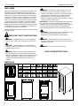
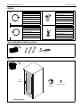
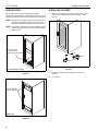
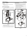
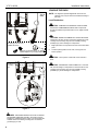
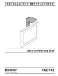
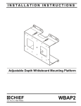
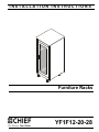
INSTALLATION INSTRUCTIONS
Furniture Racks
Spanish Product Description
German Product Description
Portuguese Product Description
Italian Product Description
Dutch Product Description
French Product Description
YF1F12-20-28
YF1F12-20-28
Installation Instructions
DISCLAIMER
Milestone AV Technologies and its affiliated corporations and
subsidiaries (collectively "Milestone"), intend to make this
manual accurate and complete. However, Milestone makes no
claim that the information contained herein covers all details,
conditions or variations, nor does it provide for every possible
contingency in connection with the installation or use of this
product. The information contained in this document is subject
to change without notice or obligation of any kind. Milestone
makes no representation of warranty, expressed or implied,
regarding the information contained herein. Milestone assumes
no responsibility for accuracy, completeness or sufficiency of
the information contained in this document.
WARNING: Exceeding the weight capacity can result in
serious personal injury or damage to equipment! It is the
installer’s responsibility to make sure the combined weight of
all components located within the rack does not exceed
500 lbs (226.8 kg). Use with products heavier than the
maximum weight indicated may result in instability or collapse
of the rack causing possible injury.
IMPORTANT ! : Minimum spacings between the Accessories
and components and the (AV) Equipment Cabinet shall be
maintained for safe operation of the equipment when installed in
accordance with the National Electric Code, ANSI/NFPA 702008. Operating temperature inside rack shall not exceed 104° F.
Chief® is a registered trademark of Milestone AV Technologies.
All rights reserved.
WARNING: Use this mounting system only for its intended
IMPORTANT SAFETY INSTRUCTIONS
use as described in these instructions. Do not use
attachments not recommended by the manufacturer.
WARNING: A WARNING alerts you to the possibility of
WARNING: Never operate this mounting system if it is
serious injury or death if you do not follow the instructions.
damaged. Return the mounting system to a service center for
examination and repair.
CAUTION: A CAUTION alerts you to the possibility of
damage or destruction of equipment if you do not follow the
corresponding instructions.
WARNING: Do not use this product outdoors.
--SAVE THESE INSTRUCTIONS--
WARNING: Failure to read, thoroughly understand, and
follow all instructions can result in serious personal injury,
damage to equipment, or voiding of factory warranty! It is the
installer’s responsibility to make sure all components are
properly assembled and installed using the instructions
provided.
DIMENSIONS
MODEL
WEIGHT CAPACITY
LBS (KG)
HEIGHT
UNITS
500 (227)
500 (227)
500 (227)
12
12
20
OVERALL
34 (863.6)
YF1F1228B
YF1F2028H
A
B
30 (762)
30 (762)
30 (762)
24.12 (612.6) 26.63 (676.4)
24.12 (612.6) 26.63 (676.4)
C
D
2
34 (863.6)
34 (863.6)
Installation Instructions
YF1F12-20-28
LEGEND
Tighten Fastener
Open-Ended Wrench
Apretar elemento de fijación
Llave de boca
Befestigungsteil festziehen
Gabelschlüssel
Apertar fixador
Chave de bocas
Serrare il fissaggio
Chiave a punte aperte
Bevestiging vastdraaien
Steeksleutel
Serrez les fixations
Clé à fourche
Loosen Fastener
Phillips Screwdriver
Aflojar elemento de fijación
Destornillador Phillips
Befestigungsteil lösen
Kreuzschlitzschraubendreher
Desapertar fixador
Chave de fendas Phillips
Allentare il fissaggio
Cacciavite a stella
Bevestiging losdraaien
Kruiskopschroevendraaier
Desserrez les fixations
Tournevis à pointe cruciforme
TOOLS REQUIRED FOR INSTALLATION
#2
7/16"
PARTS
A (1)
[F1 rack]
B (4)
[Caster]
C (4)
[Caster spacer]
(YF1F2828 shown)
3
YF1F12-20-28
Installation Instructions
INTRODUCTION
INSTALLING CASTERS
The F1 Series racks may be configured with optional
accessories (not included) such as levelers, fan panels, etc. All
accessory installation instructions accompany the accessories.
1.
Attach one caster (B) to each lower corner of the F1 rack
using one F1 caster spacer (C) for each caster. (See
Figure 3)
NOTE: The bottom cover panel may be removed for wire entry
or may be replaced with a filtered fan panel. Follow
instructions included with the fan panel. (See Figure 1)
NOTE: The panels on the back door may be replaced with fan
panels. Follow instructions included with the fan panel.
(See Figure 2)
May be removed
for wire access or
replaced with a fan panel
(C) x 1
1
Figure 3
(Door removed for clarity)
Figure 1
May be replaced
with fan panels.
(Rear view)
Figure 2
4
(B) x 1
2.
Lift rack to upright vertical position after casters are
installed.
3.
Lock casters.
Installation Instructions
YF1F12-20-28
OPTIONAL ASSEMBLY
Hinge Adjustment
Levelers
If necessary, the door hinges may be used to adjust the depth,
horizontal or vertical placement of the doors (See Figure 5).
1.
Add optional levelers to the rack following instructions
included with the levelers.
Doors (Change hinged side)
NOTE: The doors can be changed to open on the opposite side
from the way they shipped.
1.
1.
Adjusting these screws will allow vertical adjustment (up
and down) of the door. (See Figure 5)
2.
Adjusting this screw will allow depth adjustment (into and
out from rack) of the door. (See Figure 5)
3.
Adjusting this screw will allow horizontal adjustment (side to
side) of the door. (See Figure 5)
Open door to expose hinge at top and bottom of door. (See
Figure 4)
2
Rack
Side
3
Inside of
front door
Hinge
tab
Door
1
2
Door hinge
3
1
(Top of rack removed
for clarity)
e
sid
ck
a
R
Do
or
Figure 4
2.
Squeeze hinge tab at top and bottom of door and pull door
straight out to remove from rack.
3.
Turn door over and re-insert hinges into other side of rack.
4.
Slide doors into rack until the hinges "click" into the racks.
Figure 5
5
YF1F12-20-28
Installation Instructions
LOADING THE RACK
(front
view of
rack)
NOTE: The alignment panels shipped with the racks are
optional. They may be removed to facilitate loading of
the racks.
Load Distribution
CAUTION: DAMAGE COULD RESULT FROM LIFTING
RACK WITH COMPONENTS INSTALLED! Components
should be installed only AFTER rack is in an upright vertical
position.
CAUTION: BEGIN PLACEMENT OF LOAD AT BOTTOM
Grounding screw and nut
installed at factory
Earthing symbol IEC 60417 No. 5019
affixed adjacent to grounding terminal.
Figure 6
OF RACK! Load rack, moving from bottom toward top of rack.
Loading rack incorrectly may result in instability causing
possibly injury and/or damage to components.
1.
Begin placement of components into the rack at the lowest
point.
2.
Continue placing items into the rack, moving from the
bottom upward.
CAUTION: The top of the unit should not be used as a
shelf.
Locations of
grounding
lugs
CAUTION: DISTRIBUTE LOAD CORRECTLY! Load rack
with 2/3 total weight of components in the lower half of rack.
Loading rack incorrectly may result in instability causing
possible injury and/or damage to components.
Figure 7
DANGER: IMPROPER WIRING CAN LEAD TO DEATH
OR SEVERE PERSONAL INJURY! Grounding must be
installed by qualified personnel using a UL Recognized No.
12AWG Green and Yellow grounding wire connected to
grounding lug on rack.
6
Installation Instructions
YF1F12-20-28
7
YF1F12-20-28
Installation Instructions
USA/International
Europe
Chief Manufacturing, a products division
of Milestone AV Technologies
8800-002171 Rev01
2013 Milestone AV Technologies, a
Duchossois Group Company
www.chiefmfg.com
05/13
Asia Pacific
A
P
F
A
P
F
A
6436 City West Parkway, Eden Prairie, MN 55344
800.582.6480 / 952.225.6000
877.894.6918 / 952.894.6918
Franklinstraat 14, 6003 DK Weert, Netherlands
+31 (0) 495 580 852
+31 (0) 495 580 845
Office No. 1 on 12/F, Shatin Galleria
18-24 Shan Mei Street
Fotan, Shatin, Hong Kong
P 852 2145 4099
F 852 2145 4477