1
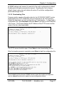
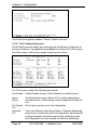
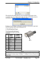
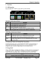
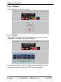
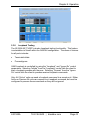
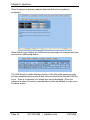
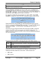
LGC340A
IE GIGA MC TX/SFP
This standalone device provides two
10-/100-/1000-BASE-T copper ports
and two SFP ports.
TRADEMARKS USED IN THIS MANUAL
Black Box and the Double Diamond logo are registered trademarks of BB
Technologies, Inc.
Any other trademarks mentioned in this manual are acknowledged to be the
property of the trademark owners.
Page 2
724-746-5500 | blackbox.com
LGC340A
FCC and IC RFI Statements
FCC and Industry Canada RF Interference Statements
Class A Digital Device (using 48V Telco type power). This equipment generates,
uses, and can radiate radio-frequency energy, and if not installed and used
properly, that is, in strict accordance with the manufacturer’s instructions, may
cause interference to radio communication. It has been tested and found to comply
with the limits for a Class A computing device in accordance with the specifications
in Subpart B of Part 15 of FCC rules, which are designed to provide reasonable
protection against such interference when the equipment is operated in a
commercial environment. Operation of this equipment in a residential area is likely
to cause interference, in which case the user at his own expense will be required to
take whatever measures may be necessary to correct the interference.
Changes or modifications not expressly approved by the party responsible for
compliance could void the user’s authority to operate the equipment.
This digital apparatus does not exceed the Class A limits for radio noise emission
from digital apparatus set out in the Radio Interference Regulation of Industry
Canada.
Le présent appareil numérique n’émet pas de bruits radioélectriques dépassant les
limites applicables aux appareils numériques de la classe A prescrites dans le
Règlement sur le brouillage radioélectrique publié par le Industrie Canada.
Class B Digital Device (using all other power options). This equipment has been
tested and found to comply with the limits for a Class B computing device pursuant
to Part 15 of the FCC Rules. These limits are designed to provide reasonable
protection against harmful interference in a residential installation. However, there
is no guarantee that interference will not occur in a particular installation. This
equipment generates, uses, and can radiate radio frequency energy, and, if not
installed and used in accordance with the instructions, may cause harmful
interference to radio communications. If this equipment does cause harmful
interference to radio or telephone reception, which can be determined by turning the
equipment off and on, the user is encouraged to try to correct the interference by
one of the following measures:
• Reorient or relocate the receiving antenna.
• Increase the separation between the equipment and receiver.
• Connect the equipment into an outlet on a circuit different from that to which the
receiver is connected.
• Consult an experienced radio/TV technician for help.
CAUTION
Changes or modifications not expressly approved by the party responsible for
compliance could void the user’s authority to operate the equipment.
LGC340A
724-746-5500 | blackbox.com
Page 3
FCC and IC RFI Statements
To meet FCC requirements, shielded cables and power cords are required to
connect this device to a personal computer or other Class B certified device.
This digital apparatus does not exceed the Class B limits for radio noise emission
from digital apparatus set out in the Radio Interference Regulation of Industry
Canada.
Page 4
724-746-5500 | blackbox.com
LGC340A
Certifications
Certifications
Class 1 Laser product, Luokan 1 Laserlaite,
Laser Klasse 1, Appareil A’Laser de Classe
European Directive 2002/96/EC (WEEE) requires that any equipment that
bears this symbol on product or packaging must not be disposed of with
unsorted municipal waste. This symbol indicates that the equipment should be
disposed of separately from regular household waste. It is the consumer’s
responsibility to dispose of this and all equipment so marked through
designated collection facilities appointed by government or local authorities.
Following these steps through proper disposal and recycling will help prevent
potential negative consequences to the environment and human health. For
more detailed information about proper disposal, please contact local
authorities, waste disposal services, or the point of purchase for this equipment.
LGC340A
724-746-5500 | blackbox.com
Page 5
Table of Contents
Table of Contents
Part Numbers ...................................................................................................... 8 1. Specifications ......................................................................................... 9 2. Overview: About the IE GIGA MC TX/SFP ......................................... 10 3. Configuration ........................................................................................ 11 3.1 Operations, Administration and Maintenance (OAM) .......................... 11 3.2 iView² Management Software .............................................................. 12 3.3 iView2 (iConfig view)............................................................................. 13 3.4 Configuration via DIP Switch Settings.................................................. 13 3.4.1 DIP Switch Configuration............................................................. 14 3.5 Configuration via serial/Telnet (CLI) or iView2 ..................................... 14 3.5.1 Configuration Options .................................................................. 14 3.5.2 Basic Device Configuration Using the CLI .................................. 15 3.5.3 Commands List (Space Bar) ....................................................... 20 3.5.4 Version......................................................................................... 27 3.5.5 Viewing Port Statistics (ifstats) .................................................... 27 3.5.6 Viewing Port RMON Statistics (rmstats)...................................... 27 3.5.7 System Description (sysDescr) ................................................... 28 3.5.8 Reboot ......................................................................................... 28 3.5.9 (Operation and Administration Management) OAM .................... 28 3.5.10 Viewing SFP Statistics (sfpstats)................................................. 29 3.5.11 Unit............................................................................................... 29 3.5.12 Port Configuration (port) .............................................................. 30 3.6 Configuration File Save/Restore Function ........................................... 31 3.6.1 Saving a Configuration File to Disk: ............................................ 31 3.6.2 Uploading a Saved Configuration File through iView2................. 32 3.7 RJ-45 Data Port Pinout ........................................................................ 33 3.8 RS-232 Serial Console Port ................................................................. 34 4. Install the IE GIGA MC TX/SFP ........................................................... 35 4.1 Powering the IE GIGA MC TX/SFP...................................................... 35 4.1.1 DC Terminal Block Wiring Instructions ........................................ 35 4.2 Mini-Serial Port..................................................................................... 36 4.3 SFP Ports ............................................................................................. 36 5. Operation.............................................................................................. 37 5.1 LED Operation...................................................................................... 37 5.2 Autocross Feature for Twisted Pair Connections................................. 37 5.3 Using iView2 ......................................................................................... 37 5.3.1 Unit Configuration ........................................................................ 39 Page 6
724-746-5500 | blackbox.com
LGC340A
Table of Contents
5.3.2 Port Configuration........................................................................ 39 5.3.3 Bandwidth .................................................................................... 40 5.3.4 Tables .......................................................................................... 40 5.3.5 VLAN ........................................................................................... 41 5.3.6 Advanced..................................................................................... 42 5.3.7 OAM AH....................................................................................... 42 5.3.8 Loopback Testing ........................................................................ 43 5.3.9 OAM CFM.................................................................................... 45 5.3.10 Agent Info .................................................................................... 48 6. Troubleshooting.................................................................................... 50 7. Contacting Black Box ........................................................................... 51 8. Fiber Optic Cleaning Guidelines .......................................................... 52 9. Electrostatic Discharge Precautions .................................................... 53 Glossary ............................................................................................................ 54 LGC340A
724-746-5500 | blackbox.com
Page 7
Part Numbers
Part Numbers
Part Number
LGC340A
Page 8
Description
IE GIGA MC TX/SFP
724-746-5500 | blackbox.com
LGC340A
Chapter 1: Specifications
1. Specifications
Operating Temperature
Storage Temperature
Humidity
Dimensions
Current Draw
DC Terminal
DC Jack
Double-USB Power
Cable
Ethernet Connections
Standards/Compliance
LGC340A
-40°F to +185° F (-40°C to +85°C) DC
configuration
+14°F to +122° F (-10°C to +50°C) AC
-67°F to +257°F (-55°C to +125° C)
5 to 95% (non-condensing); 0 to 10,000 ft.
altitude
0.86”H x 3.66”W x 3.88”D (2.2cm H x 9.3cm W
x 9.8cm D)
1.5A @ room temperature with data and copper
SFPs
1.1A @ room temperature with fiber SFPs
48 VDC Telco
5 VDC
Spec 500mA
Note that the laptop or PC USB ports must be
2.0 or greater to provide sufficient power to the
unit.
•
SFP 1000BASE-X
•
SFP 100BASE -FX
•
SFP 10/100/1000 Copper (SGMII)
•
10/100/1000 BASE-T (Fixed Copper ports)
•
Auto Negotiation
•
Auto-Cross
•
Flow Control
•
Up to 10,240 MTU
•
Full Line-Rate Forwarding
•
IEEE 802.3x Flow Control
•
IEEE 802.3i 10BASE-T twisted pair
•
IEEE 802.3u 100BASE-TX twisted pair
•
IEEE 802.3u 100BASE-FX or SX fiber
724-746-5500 | blackbox.com
Page 9
Chapter 2: Overview
2. Overview: About the IE GIGA MC TX/SFP
The IE GIGA MC TX/SFP is an SNMP manageable standalone device
providing two fixed 10/100/1000Base-T copper ports and 2 SFP ports. The
SFP ports support fiber or copper SFPs. As a plug and play device, the IE
GIGA MC TX/SFP provides several distinct modes of operation to support a
wide range of applications. The IE GIGA MC TX/SFP provides OAM
functionality with 802.3ah (LINK-OAM ah) and 802.1ag (SERVICE-OAM ag)
supported on each port. It supports jumbo frame sizes of up to 10,240 bytes as
well as AutoCross on the copper ports. Power options for the IE GIGA MC
TX/SFP include both a standard low voltage wall transformer and a Power
Block for Office Battery or a DC Power Supply connection. As an Industrial
Ethernet device, it supports an extended temperature range of -40°C to +85°C.
A console port and a DIP Switch bay provide configuration options.
The IE GIGA MC TX/SFP can be directly managed, because it contains onboard logic. Management capability is available if the device has firmware
version 123-00A1 or higher, which can be downloaded from the Black Box site.
iView2 is a free software, posted on the website under Support/Downloads.
Please refer to page 12 for details.
The IE GIGA MC TX/SFP requires two small form-factor (SFP) modules which
provide greater flexibility in the network environment. The hot-swappable
nature of the SFPs, available in dual strand for Multi Mode and Single Mode,
and single strand fiber types for Single Mode, allow for easy configuration and
future upgrading as network demands evolve. The SFP modules must be
MSA-compliant and both DDMI and non-DDMI are supported. The fiber SFP
can support 100Mbps or 1000Mbps; while the copper SFPs support
10/100/1000Mbps and 1000Mbps.
SFPs are sold separately and meet Class 1 Laser Safety Standard.
Page 10
724-746-5500 | blackbox.com
LGC340A
Chapter 3: Configuration
3. Configuration
The IE GIGA MC TX/SFP offers a full feature set including Auto Negotiation,
Selective Advertising, AutoCross, VLANs, SNMP management, loopback
testing and OAM. Unit software updates can be downloaded through TFTP or
iView2 (iConfig view).
IE GIGA MC TX/SFP features include:
•
SNMP manageable
•
OAM AH
- IEEE 802.3ah Link OAM for per port monitoring (OAM AH)
•
OAM AH Functions
- Discovery
- Link Performance Monitoring
- Remote Loopback
- Fault Detection
- Link Fault
- Dying Gasp
- Critical Event
•
OAM CFM (SERVICE-OAM)
- IEEE 802.1ag Connectivity Fault Management (OAM CFM)
- OAM CFM Functions
- Continuity Check
- Loopback
•
Speed/duplex modes
•
802.1q VLAN
•
Extra tagging with user-defined VLAN tag Ethertype
•
Ethertype 88A8 as defined in 802.1ad
•
Command Line Interface capable (CLI)
•
Telnet
•
Password assignment via CLI, Telnet or iView²
•
DIP Switch configuration for Modes
•
Bandwidth Limiting
3.1 Operations, Administration and Maintenance (OAM)
OAM is a general term used in network management and is typically applied to
a series of standard protocols for installing, monitoring, and troubleshooting
Metropolitan Area Networks.
LGC340A
724-746-5500 | blackbox.com
Page 11
Chapter 3: Configuration
When applied to Ethernet – OAM is typically assumed to refer to the layer 2
(MAC layer), management protocols, specifically 802.3ah and 802.1ag. Layer
2 management protocols do not need higher level transport protocols to
operate, OAM data is transferred in standard multicast Ethernet frames.
802.3ah OAM:
Is a point-to-point protocol designed to verify a specific
link between two directly connected devices (over
copper or fiber), which support 802.3ah OAM. One
device must be configured to be an active OAM device,
the other a passive (typically the core switch would be
the active device, the end device passive). 802.3ah
OAM provides link status, remote fault detection and the
ability to initiate a loopback circuit.
Often referred to as Connectivity Fault Management
(CFM), is an end-to-end protocol designed to verify a
specific network path between two devices that may well
be in different geographical locations. CFM allows the
network operator to administer, monitor and debug the
network using continuity check (a heart beat message),
link trace (similar to traceroot, but operating at the MAC
layer) and finally loopback (can be likened to a layer 2
ping).
(LINK-OAM)
802.1ag:
(SERVICE-OAM)
3.2 iView² Management Software
iView² is the Black Box management software that features a Graphical User
Interface (GUI) and gives network managers the ability to monitor and control
the manageable Black Box products.
iView² is available in several versions, including a WebServer version 3.0, and
can also function as a snap-in module for HP OpenView Network Node
Manager and other third party SNMP Management software.
iView2 supports the following platforms:
•
Windows 2000
•
Windows XP
•
Windows Vista
•
Windows 7
Please see the SNMP Management Module manual for software configuration
options.
Page 12
724-746-5500 | blackbox.com
LGC340A
Chapter 3: Configuration
3.3 iView2 (iConfig view)
iView2 (iConfig view) is an in-band utility created by Black Box, used for SNMP
configuration for Black Box’s SNMP-manageable devices.
The iView2 (iConfig view) feature allows the following to be performed:
•
Set an IP address, subnet mask and default gateway
•
Define community strings and SNMP Traps
iView2 (iConfig view) also includes an authorized IP address system and
restricted access to MIB groups which are supported by Black Box’s
manageable devices. These extra layers of security do not affect SNMP
compatibility. iView2 (iConfig view) can upload new versions of the system
software and new MIB information. It also includes diagnostic capabilities for
faster resolution of technical support issues.
3.4 Configuration via DIP Switch Settings
The IE GIGA MC TX/SFP can be configured in one of the following ways via
DIP Switch settings:
Configuration Description
Method
4-Port Switch
In this mode, the unit acts as a standard 4-port MAC-layer
(default)
switch. In this configuration, IEEE802.3ah Passive is
enabled on both fiber ports, and can be enabled on the RJ45 ports through the CLI.
Dual
In this configuration, the unit functions as two independent
Converter
(SFP to TX) media converters and traffic never passes
mode
between the two converters.
1+1 SFP
In this mode, the “SFP A” port (fiber or copper) is connected
Protection
through the switch to the drop ports as the main link. The
Non-Revertive “SFP B” port (fiber or copper) is active into the MAC switch,
mode
but no connection inside the switch is made; in this way, the
“SFP B” line is held as the standby line. The “SFP B” line is
held in the LINK state for testing and line verification, but
does not actively carry user data.
When a fault is detected on the active line, all customer
traffic is switched to the “SFP B” port. With non-Revertive
mode data is not resumed by “SFP A” port.
1+1 SFP
In this mode, the “SFP A” port (fiber or copper) is connected
Protection
through the switch to the drop ports as the main link. The
Revertive
“SFP B” port (fiber or copper) is active into the MAC switch,
mode
but no connection inside the switch is made; in this way, the
LGC340A
724-746-5500 | blackbox.com
Page 13
Chapter 3: Configuration
Configuration
Method
Description
"SFP B" line is held as the standby line. The “SFP B” line is
held in the LINK state for testing and line verification, but
does not actively carry user data.
When a fault is detected on the active line, all customer
traffic is switched to the “SFP B” port. Once the “A” port is
no longer in a fault condition, data is resumed on that port.
NOTE
Revertive and Non-Revertive modes can only operate on the ports with SFPs, not the
fixed copper ports.
3.4.1
DIP Switch Configuration
Console Port
DIP
Switch
1
2
Name
Dual
1+1
3
1+1 Revert
4
5
6
LoSpd A
LoSpd B
Reserved
Description
Enable dual channel
Provides 1+1 protection with non-revertive
switching
Provides 1+1 protection with revertive
switching
Optional-for future use
Optional-for future use
Default
Setting
OFF
OFF
OFF
OFF
OFF
3.5 Configuration via serial/Telnet (CLI) or iView2
The IE GIGA MC TX/SFP includes many features that are configurable via a
serial/Telnet session (CLI) or through iView² (SNMP Management view or
iConfig view).
3.5.1
Configuration Options
The following options are configurable through both the iView2 (iConfig view)
and Serial/Telnet.
Feature
Loopback
Auto Negotiation
Page 14
iView²
9
9
Serial/Telnet
9
9
724-746-5500 | blackbox.com
LGC340A
Chapter 3: Configuration
Feature
Force Mode
FlowControl
VLANs
IP Address
Subnet Mask
Default Gateway
MIB Community
Traps Assignment
Users
Passwords
Access Level
Reboot
Frame size selection
Bandwidth Limiting
iView²
9
9
9
9
9
9
9
9
9
9
9
9
9
9
Serial/Telnet
9
9
9
9
9
9
9
9
9
9
9
9
9
9
The following table presents management options configurable via iView2
(iConfig view) or a serial/Telnet session.
Feature
PROM Software Download/Upload
Telnet Session
Software Download Setup (TFTP)
DHCP
Restore Configuration
Save Configuration
3.5.2
iView2
9
9
9
9
Serial/Telnet
9
9
9
9
Basic Device Configuration Using the CLI
After running through an initial self test, the screen will display the following
message:
Press Enter for Device Configuration.
LGC340A
724-746-5500 | blackbox.com
Page 15
Chapter 3: Configuration
Press Enter to open the main configuration screen. This screen allows the
user to set the IP address and the destination IP address for traps with the
community string, read/write access and password as usual.
Saved Values. (These values will be active after reboot)
IP Address
- 10.10.10.10
Subnet Mask
- 255.255.255.0
Default Gateway - 0.0.0.0
DHCP is Not Active
Current Values. (These values are in use now)
IP Address
- 10.10.10.10
Subnet Mask
- 255.255.255.0
Default Gateway - 0.0.0.0
Community String: public
Access:
r/w
Press I to enter new saved parameter values. Press P to change Password.
Press T to enter new Trap Destination. Press K to remove All Trap
Destinations.
Press C to enter new Community String. Press U to remove All Community
Strings.
Press E to End session. Type REBOOT to reboot unit. Press D for DHCP
On/Off.
Press SpaceBar for additional commands.
This screen contains the following information and options:
3.5.2.1 Saved and Current Values
Saved values display the changes made during the current session and current
values display the values currently in use:
•
IP Address (IP address of SNMP agent)
•
Subnet Mask (mask to define IP subnet to which agent is connected)
•
Default Gateway (default router for IP traffic outside of the subnet)
3.5.2.2 Command List
I = Enter new Saved Parameter Values
P = Change the Password*
T = Enter new Trap Destinations
K = Remove All Trap Destinations
C = Create SNMP Community Strings
U = Delete All SNMP Community Strings
E = End the session*
Reboot = Reboot the unit (may result in short data loss)
D = Enable or disable DHCP
Space Bar = Opens the device specific configuration options screen.
Page 16
724-746-5500 | blackbox.com
LGC340A
Chapter 3: Configuration
*The screens illustrated in this manual show capabilities for users with Admin
rights. Individuals with User-level rights can only view port status and port
settings, change their password, end a session, and reboot the unit.
NOTE
It is necessary to reboot the IE GIGA MC TX/SFP after making any modifications to the
Saved Values for the changes to take effect. To reboot, type Reboot at the prompt on
the Main Configuration screen.
3.5.2.3 Assigning IP Information
To modify the Saved Parameter Values (i.e., assign IP address and subnet
mask), press I. The system prompts for the IP address and subnet mask for
the connected device. Press Enter after each entry. A default gateway can
also be assigned, or press Enter to skip. When finished, press Enter, then
type reboot for changes to take effect. The Current Values can only be saved
and acted on after the IE GIGA MC TX/SFP has been successfully rebooted.
3.5.2.4 Password Protection for Serial Port Connections
Password/username is not offered for the serial port by default. This allows the
end user to quickly access the device for some basic configuration capability.
Password protection is provided for the serial configuration process by pressing
P on the main configuration screen. Enter a password, keeping in mind that
passwords are case-sensitive and must not exceed eight characters or include
spaces, and press Enter. This password will be requested whenever logging
on. To remove password protection, select P and, instead of entering a
password, press Enter.
Passwords have the following requirements:
•
The password must be between 1 and 8 characters long
•
The password consists of a combination of any ASCII characters except
spaces
•
Passwords are case sensitive
Passwords are a way to make the management of the Black Box devices
secure, but these password lists must be stored and maintained.
3.5.2.5 Assigning SNMP Trap Destinations
Traps are sent by the manageable device to a management PC when a certain
event takes place. To enter a trap destination, press T. When prompted, enter
a New IP Address prompt, enter the appropriate IP address of the destination
device and press Enter. Then, type the name of the community string (that the
destination device has been configured to accept) and press Enter. Select
whether the trap is for SNMP version 1 or 2c and press Enter. This function
LGC340A
724-746-5500 | blackbox.com
Page 17
Chapter 3: Configuration
enables ALL of the device traps. Supported traps include: Link Down, Link Up,
and Last Gasp.
3.5.2.6 Removing Trap Destinations
To remove all trap destinations, press K. Press Y to continue to confirm or N to
abort and remove all trap destinations. Press Enter to finish.
This function will delete all trap destinations. To selectively delete trap
destinations or to disable/enable Traps, use iView2 (iConfig view) to configure
the device.
3.5.2.7 Creating Community Strings
Community strings add a level of security to a network. The default community
string is named "public" and has read/write access. For security, "public"
should be replaced with custom community strings such as ones created with
read-only access (for general use), and another with read/write access (for the
administrator).
To create a new community string, go to the main configuration screen and
press C. Enter the name of the new community (up to 16 characters, no
spaces) and press Enter. Then type one of the following to assign the
community string’s access rights:
•
R = read-only access
•
W = read/write access
•
Enter = abort
After entering R or W, press Enter. To finish, press Enter and reboot.
3.5.2.8 Deleting Community Strings
To delete all community strings, perform the following:
Press U. The "Are you sure you want to delete all future strings?" prompt is
displayed. Press Y when prompted to proceed and delete all community
strings, N to abort. Press Enter to finish.
This function will delete ALL community strings. To selectively delete
community strings, use iView2 (iConfig view) to configure the device.
3.5.2.9 Ending the Session
Press E to end a serial port or Telnet/HyperTerminal session before
disconnecting the serial cable. This will stop the continuous stream of data to
the serial port.
Page 18
724-746-5500 | blackbox.com
LGC340A
Chapter 3: Configuration
3.5.2.10
Rebooting the Unit
To reboot the IE GIGA MC TX/SFP, type reboot from the main screen or the
command menu.
3.5.2.11
Enabling/Disabling DHCP
To toggle DHCP on the IE GIGA MC TX/SFP between enable and disable,
press D and then Y. Press the Space Bar once to return to the main screen
without making any changes.
DHCP Disable (Static IP Addressing)
DHCP is disabled in the default configuration. Initially, modules are assigned a
Static default IP Address of 10.10.10.10. Changes to the Static IP Address can
be added manually through iView2 (iConfig view) or a Console session. The
changes will be initiated following reboot of the module.
DHCP Enable (Dynamic IP Addressing)
If a DHCP server is present on the network and DHCP is enabled, the DHCP
client will initiate a dialogue with the server during the boot up sequence. The
server will then issue an IP address to the management card. Once the new IP
address is received, the SNMP Management Module will reboot so that the new
IP address will take effect. Refer to About Serial Port Configuration for more
information about Enabling/Disabling DHCP.
When there is no DHCP server on the network, use the serial configuration to
manually set the IP addresses.
When DHCP is enabled, the IP address (default 10.10.10.10 or a previously
used IP address, or user-configured) is saved. When DHCP is disabled, the
saved IP address will be reinstated and the device will reboot.
DHCP servers give out lease times: devices renew their leases based on the
administrator-specified time. If a device cannot renew its lease, and the lease
expires, the device will be given the IP address 10.10.10.10 and will reboot.
LGC340A
724-746-5500 | blackbox.com
Page 19
Chapter 3: Configuration
3.5.3
Commands List (Space Bar)
The IE GIGA MC TX/SFP also includes several device-specific options. To
access these options, press the Space Bar from the Main Configuration
screen, type the name of the action to be performed (as shown below) and
press Enter.
Command
cleandb
download
accounts
vlan
bw
version
ifstats
rmstats
sysDescr
reboot
oam
sfpstats
unit
port
Description
Reboots the unit with a clean database. This removes all information
from the database and sets the unit to factory defaults.
Downloads firmware via the TFTP protocol
Allows the addition for User, Superuser, Admin
Provides selection of two modes of operation to support all VLAN
configurations.
Displays settings for Bandwidth configuration
Displays the unit’s firmware and hardware version
Displays interface statistics
Displays remote monitoring (RMON) statistics on packets received as
defined in RFC 2819 for RMON.
Allows the editing of sysName, sysDescr, and Port information
Allows a soft reboot of the unit after changes are made by the end
user
Enable/disable OAM
Provides information about the wavelength, serial number, output
power, BER and other information. Requires an SFP with DDMI.
Unit global settings, frame size selection. Unit OAM enable must be
enabled for AH and AG to function.
Displays the port status and allows changes to port settings, such as
duplex status and speed.
3.5.3.1 Cleandb
Entering cleandb reboots the unit with its database cleaned depending on the
option selected. Users are presented with two, sequential options, first to reset
Page 20
724-746-5500 | blackbox.com
LGC340A
Chapter 3: Configuration
all SNMP settings and, second, to reset all of the unit’s configuration to default.
Enabling the first option presents the second. Resetting the unit to factory
default values (option two) will delete all custom IP and other configurations
performed through iView².
3.5.3.2 Downloading Files
Firmware and/or saved configuration data for the IE GIGA MC TX/SFP can be
downloaded via a TFTP connection from a central server via TFTP protocol.
Initiate this download via serial configuration or Telnet session. To download a
configuration file, type download and press Enter to be taken to the Download
a file screen. This screen displays the IP Address of the TFTP server and the
name of the file to be downloaded:
The TFTP server should be open. Press Enter to start downloading the file.
After the transfer process is complete, press Enter to load the configuration file:
Once loaded into the device's SNMP memory area, the system prompts the
user to reboot the device to make the new configuration active.
LGC340A
724-746-5500 | blackbox.com
Page 21
Chapter 3: Configuration
3.5.3.3 Accounts
The following are the three levels for CLI or Telnet account access:
User:
View status, change own password, and reboot.
Operator:
All User privileges mentioned above, plus ability to
change settings.
Administrator: Operator privileges mentioned above, plus ability to
add/delete
accounts and reinitialize the unit to default settings
(cleandb).
3.5.3.4 VLAN Configuration
The ports can be assigned as a trunk or access port.
When configuring a trunk port, an Ethertype can be user-defined (a trunk port is
also defined as a provider port based on 802.1ad). If an Ethertype value
comes in a trunk port and is different than the user-defined Ethertype, it will be
treated as an unrecognized VLAN tagged frame. If configuring the port as an
access port, enter a VLAN ID between 1 and 4,094. Possible priority settings
are 0 (lowest priority) through 7 (highest priority).
Page 22
724-746-5500 | blackbox.com
LGC340A
Chapter 3: Configuration
NOTE
When an Ethertype or VLAN ID is assigned, the same values need to be configured at
the end device (router, etc) to avoid network configuration problems.
Operational Mode Configuration
There are two modes of operation that can be configured through the
Serial/Telnet session: Mode 1, which supports a mixture of tagged and
untagged traffic, and Mode 2 Extra tagging.
The configuration screen is accessed by typing vlan and pressing Enter from
the Additional Commands screen. The system displays the current operation
mode screen. Press the Space Bar to select the other mode.
Operation Mode 1 – Mixed Tagged and Untagged Frames
In this mode, all tagged and untagged frames pass on any given port.
Management to the device can be tagged or untagged.
LGC340A
724-746-5500 | blackbox.com
Page 23
Chapter 3: Configuration
Press the down arrow on the computer keyboard to access additional
configuration selections.
WARNING
If a VLAN # is added to a port and is the same VLAN # assigned for a tag on
management traffic, saving these changes will disrupt management indefinitely.
Operation Mode 2 Port Based Xtra Tagging
Any port can be configured for extra tags on the frames.
Press the down arrow on the computer keyboard to access the additional
configuration commands.
Page 24
724-746-5500 | blackbox.com
LGC340A
Chapter 3: Configuration
3.5.3.5 Bandwidth (bw)
Displays settings for Bandwidth configuration.
SFP A/B Ports
Ingress
Bandwidth Limit
(CIR)
Max Burst
Allocation size
(BA)
Ingress Burst
Allocation
Egress Traffic
Shaping
LGC340A
Monitors the traffic entering the unit (ingress), discarding
traffic that exceeds a fixed Committed Information Rate
(CIR) plus Burst Allocation (BA). Frames are not held in
queue, they either meet the bandwidth limits and are
accepted into the unit or they are dropped.
The BA size is specified in bits; the # of bits above the
bandwidth limit before packets are thrown away.
Bandwidth Limiting can be set at Ingress of each port
individually by setting the MAX Bandwidth Limit in
bits/Sec. and the BA in bits. Traffic in excess of the
Bandwidth limit plus BA for any time interval will be
dropped. This function utilizes an advanced “Leaky
Token-Bucket” algorithm to provide typical resolution
under 5% of the set values at all data rate and frames
sizes.
Egress Traffic shaping actively controls the transmitter
and hard limits the maximum frame rate that can be sent.
Frames can be delayed in the internal buffers of the unit,
waiting their turn to be sent. If the internal buffers are full,
excess traffic will be dropped. The Unit Rate Control can
be used to alleviate this.
724-746-5500 | blackbox.com
Page 25
Chapter 3: Configuration
TX1/2
Ingress Bandwidth
Limit
(CIR)
Max Burst Allocation
size (BA)
Ingress Burst
Allocation
Monitors the traffic entering the unit (ingress),
discarding traffic that exceeds a fixed Committed
Information Rate (CIR) plus Burst Allocation (BA).
Frames are not held in queue, they either meet the
bandwidth limits and are accepted into the unit or
they are dropped.
The BA size is specified in bits; the # of bits above
the bandwidth limit before packets are thrown away.
Bandwidth Limiting can be set at Ingress of each port
individually by setting the MAX BW Limit in bits/Sec.
and the BA in bits. Traffic in excess of the Bandwidth
limit plus BA for any time interval will be
dropped. This function utilizes an advanced “Leaky
Token-Bucket” algorithm to provide typical resolution
under 5% of the set values at all data rate and
frames sizes.
Actively controls the transmitter and hard limits the
maximum frame rate that can be sent. Frames can
be delayed in the internal buffers of the unit, waiting
their turn to be sent. If the internal buffers are full,
excess traffic will be dropped. The Unit Rate Control
can be used to alleviate this.
Choose Layer 1, 2 or 3 for the counter, this will
determine how my bytes from the Ethernet frame are
to be included in the calculations.
Egress Traffic
Shaping
OSI Level Used in
Calculations
(Open Systems
Interconnect, referring
to the seven layers
for TCP/IP)
Layer 1:
Layer 2:
Layer 3:
Preamble + DA to CRC + IFG
Frames DA to CRC
Frames DA to CRC – 18
(- 4 if frame is tagged)
Explanations:
Unit Rate Control
Enable/Disable
Page 26
= 8 bytes
Preamble
= EtherNet Destination Address
DA
= EtherNet Checksum
CRC
= 12 bytes
IFG
Allows the end user to globally configure all
Bandwidth settings when enabling Unit Rate Control
(Flow Control). If the END device connected to the
port also has Flow Control enabled, this will ensure
packets will not be dropped.
724-746-5500 | blackbox.com
LGC340A
Chapter 3: Configuration
OSI NOTES
The Bandwidth Limit functions can be adjusted to only count the Layer 1, 2, or 3
portions of the physical line rate. Layer 1 is used to relate Bandwidth to the physical
line rate where a 100BaseT Ethernet line can carry a MAX bandwidth of 100Mbps.
Layer 2 may be more useful when the Ethernet Frame may be carried over several
different physical protocols such as SONET or SDH. Only the bandwidth required by
the Ethernet frame is counted, making this a more consistent number over different
protocols. Layer 3 counting could be used when a relationship to the actual customer
data or line payload is required. If a 10 Mbps customer file needs to be sent in one
second, then a minimum bandwidth limit of 10Mbps would need to use Layer 3 counting
to allow this.
It must be noted that only Layer 1 counting is not affected by the size of the Ethernet
frame. At 64 byte Ethernet frames, the MAX bandwidth the line can support at Layer 2
is only 76.2% of the line rate. This maximum falls to 54.8% of the line rate when
counting is further limited by only counting Layer 3 payload data.
3.5.4
Version
Entering version will display the version of the firmware operating the IE GIGA
MC TX/SFP. Settings should be saved prior to reboot.
3.5.5
Viewing Port Statistics (ifstats)
To view port statistics on the IE GIGA MC TX/SFP, enter ifstats. This will open
a screen displaying information on packets received and transmitted as defined
by MIB-II standard RFC 1213.
Pressing the Space Bar will refresh the data on the screen.
3.5.6
Viewing Port RMON Statistics (rmstats)
To view port RMON (Remote MONitoring) statistics on IE GIGA MC TX/SFP,
enter rmstats. This will display RMON information on packets received as
defined in RFC 2819 for RMON.
LGC340A
724-746-5500 | blackbox.com
Page 27
Chapter 3: Configuration
Pressing the Space Bar will refresh the data on the screen.
3.5.7
System Description (sysDescr)
The sysDescr allows the end user to enter a description for the Black Box
device. Within the iView² GUI, a name or some kind of identifier can be
entered into the text box labeled Description. Once that description is saved,
the identifier will be maintained, even if power is interrupted to the unit.
3.5.8
Reboot
Entering reboot will save settings and reboot the IE GIGA MC TX/SFP.
3.5.9
(Operation and Administration Management) OAM
Two modes of operations control the OAM function, Passive and Active.
Passive mode is the default mode.
OAM AH passive/active is available on the fiber SFP ports and TX ports
•
Supports Discovery functions on the SFP ports.
Page 28
724-746-5500 | blackbox.com
LGC340A
Chapter 3: Configuration
•
Supports reporting OAM Flag Events (Link Fault, Critical Event, and Dying
Gasp)
•
Supports Loopback
3.5.10 Viewing SFP Statistics (sfpstats)
To view SFP statistics on the IE GIGA MC TX/SFP, enter sfpstats. This will
open a screen displaying SFP information, including vendor, serial number, bit
rate and other options.
Pressing the Space Bar will refresh the data on the screen.
3.5.11 Unit
Advertise FlowC and Force FlowCtrl - This is the FlowControl feature.
• When using FlowControl functionality on any port, enable Global
FlowControl. Then, configure each port individually.
•
When using Auto Negotiation and FlowControl, set Advertise FlowC to
Advertise Flow and set Force FlowCtrl to Flow Auto.
•
Set Advertise FlowC to No Flow to disable FlowControl on a given port.
•
When using FlowControl and Force Mode on a given port, set Advertise
FlowC to Advertise Flow and set Force FlowCtrl to Frc FlowCt.
Unit
FlowControl
This enables/disables FlowControl functionality on the
unit and must be enabled for FlowControl to function
on any port.
Unit FlowControl displays the following screen:
LGC340A
724-746-5500 | blackbox.com
Page 29
Chapter 3: Configuration
Unit FlowControl globally enables “Pause” frames to be sent.
3.5.12 Port Configuration (port)
Serial/Telnet sessions display port status as well as allowing configuration of
some port features. Type port and press Enter to be taken to the Port screen.
From this screen, view the port speed, duplex and link status.
The Port screen contains the following commands:
Port Enable Enable/Disable the port. (Select Enable to enable the port.)
Admin
Status
Port Speed
Ctrl
Advertise
Ctrl
Page 30
Set Administration level. (Select UP to enable management
through the port.) Both settings must be enabled to enable the
port.
Set the port manually or for Auto Negotiation.
This is the Selective Advertising feature. Selective Advertising,
when used in combination with Auto Negotiation, advertises the
configured speed and duplex mode for the twisted pair ports.
Auto Negotiation must be enabled for Selective Advertising.
724-746-5500 | blackbox.com
LGC340A
Chapter 3: Configuration
NOTE
Selective Advertising must be used when connecting to a device that auto negotiates
and a specific speed and duplex mode is desired.
3.6 Configuration File Save/Restore Function
The Configuration File Save/Restore Function allows a user the ability to
backup all the configuration settings of a unit. With this backup, a user can
restore settings to a unit if necessary or use this backup to apply the same
settings to a different unit.
All configurable managed objects are saved in a configuration file that is stored
in the unit’s Large File Area. This includes all configurable settings such as
VLAN configurations, IP Address configuration and SNMP agent settings. The
configuration file can be transferred from the unit to a PC and saved to disk
through the iView2 (iConfig view) protocol. The configuration file can be
transferred from a PC to a unit of the same type through iView2 (iConfig view)
or TFTP into the unit’s Large File Area. After the transfer is complete, the unit
copies the configuration to flash and reboots.
The configuration file’s contents is device-type specific and can be identified by
iView2 (iConfig view) as a configuration file as well as to what type of device it is
applicable to.
3.6.1
Saving a Configuration File to Disk:
From the Administration Tab in iView2 (iConfig view) click the Save
Configuration button:
The user is prompted for a filename:
LGC340A
724-746-5500 | blackbox.com
Page 31
Chapter 3: Configuration
The user is prompted to enter any notes to the header of the saved file for
future reference when uploading the file through iView2 (iConfig view):
After the file transfer from the device to disk, the user is notified of the status:
3.6.2
Uploading a Saved Configuration File through iView2
From the Administration Tab in iView2 (iConfig view) click the Upload
Configuration button:
The user will be prompted to select a configuration file. Once selected, the
user can also view any notes that were added when the file was saved:
Page 32
724-746-5500 | blackbox.com
LGC340A
Chapter 3: Configuration
After selecting the configuration file, the file upload process begins; when
completed, the user is notified of the status and also notified that a reboot is
necessary for the new configuration to become active:
By design, the IP Address configuration currently on the device is kept intact
and not overwritten by the new configuration file.
3.7 RJ-45 Data Port Pinout
The following table lists the pin
configuration for the RJ-45 Data
connector.
Pin
Signal
Signal
Name
Direction
1000M
10/100M
1
TXD1+
Out*
2
TXD1Out*
3
RXD2+
In*
4
D3+
5
D36
RXD2In*
7
D4+
8
D4-
Pin 1
NOTE
The MDI/MDIX function will automatically adjust the direction of these signals to match
the connected unit when running 10/100Base-T. 1000Base-T will use all 4 pairs in full
duplex mode.
LGC340A
724-746-5500 | blackbox.com
Page 33
Chapter 3: Configuration
3.8 RS-232 Serial Console Port
The IE GIGA MC TX/SFP includes an RS-232 Mini Jack for the Console port to
allow the end user to launch a serial session and access a list of commands.
The serial port on the computer/terminal should be set for: 38.4K baud, 8 data
bits, 1 stop bit, no parity, no flow control. The F2 key functions as a Delete key
on VT-100 emulators.
The following table lists the pin configuration for the RS-232 3-pin Mini Jack
mating connector for the console serial port.
Pin
DB9-F Pin#
Signal Name
Direction
Tip
2
Transmit
Out of Unit
Ring
3
Receive
In to Unit
Sleeve 5
Return
Return
Page 34
724-746-5500 | blackbox.com
LGC340A
Chapter 4: Install the IE GIGA MC TX/SFP
4. Install the IE GIGA MC TX/SFP
The IE GIGA MC TX/SFP has a small form factor making it ideal for installation
in locations with limited space.
4.1 Powering the IE GIGA MC TX/SFP
The IE GIGA MC TX/SFP includes multiple powering options:
• AC adapter
• The 4-terminal DC power block
• An optional IE-Power/5V DIN railmount power supply, extended
temperature
• An optional Double-USB Power Cable (available from Black Box)
IE GIGA MC TX/SFP with optional DIN railmount power supply
4.1.1
DC Terminal Block Wiring Instructions
The IE GIGA MC TX/SFP can also be powered with the DC terminal block.
From a power source, connect to any one positive and any one negative
terminal on the IE GIGA MC TX/SFP.
TELCO (-48)
NOTE
When using stranded wire, the leads should be tinned. The DC terminal block is
protected against polarity mis-wiring. AWG24 is recommended.
LGC340A
724-746-5500 | blackbox.com
Page 35
Chapter 4: Install the IE GIGA MC TX/SFP
4.2 Mini-Serial Port
A console port, located next to the DIP Switch bay, allows the customer to use
a local RS-232 serial interface for management. A special mini-jack to DB9-F
cable is provided with the product for direct connection to a PC serial port.
NOTE
To log on through the serial port, set the computer/terminal for VT-100 emulation,
with: 38.4K baud, 8 data bits, 1 stop bit, no parity, no FlowControl.
4.3 SFP Ports
The IE GIGA MC TX/SFP SFP ports support gigabit fiber SFPs and 100Mbps
fiber SFPs, with or without Digital Diagnostics Monitoring Information (DDMI) as
well as copper SFPs available in 10/100/1000Mbps and 1000Mbps. DDMI
statistics provide real-time access to transceiver operating parameters such as
voltage, temperature, laser bias current, and both transmitter and receive
optical power. This information can be accessed through the management
system. The SFPs must be MSA-compliant, and can be purchased from Black
Box or other suppliers.
Page 36
724-746-5500 | blackbox.com
LGC340A
Chapter 5: Operation
5. Operation
5.1 LED Operation
Each IE GIGA MC TX/SFP includes SFP and RJ-45 LEDs.
SFP LED functions are as follows:
LED
Function
FLT
Glows amber when a fault is detected.
LNK
Glows green with a valid optical link.
ACTIVE Glows green when the port is active.
OFF when SFP is in standby (does not indicate activity).
OAM
Glows green when an active OAM channel is established.
RJ-45 LED functions are as follows:
LED
Function
LNK/ACT Glows green when a link is established on the TX port.
Blinks green when activity is detected on the TX port.
FDX
Glows amber when an FDX link is established on the TX port.
Not lit for HDX.
5.2 Autocross Feature for Twisted Pair Connections
All fixed twisted pair ports on the IE GIGA MC TX/SFP include AutoCross, a
feature that automatically selects between a crossover workstation and a
straight-through connection depending on the connected device.
5.3 Using iView2
iView² is Black Box’s management software, providing network management in
an easy to use GUI. Once iView² is installed on a network management PC
using a Windows operating system, use the Start menu to access iView².
NOTE
Windows SNMP services must be installed to receive traps.
LGC340A
724-746-5500 | blackbox.com
Page 37
Chapter 5: Operation
The autoscan feature of iView² will detect Black Box devices on an active
subnet and list them in the network outline. Click the connection for the IE
GIGA MC TX/SFP to open its iView² screen. To perform additional
configuration, select the iView2 iConfig view icon on the toolbar in iView². This
allows a session to be launched, and the default password/username is
admin/admin. Additional private usernames and passwords can be entered in
the USERS tab. If the list of passwords is not maintained, the usernames and
passwords can be reset by opening a CLI session and typing in the cleandb
command. This will reset all but the IP address of the device.
The following functions can be performed via iView2:
Function
Description
Unit Configuration Display/modify unit information
Port Configuration Display/modify port data
Bandwidth
Displays settings for Bandwidth configuration
Tables
Display statistics tables, including Unit and Port
tables, RMON statistics, MIB-II ifTable and SFP
Info.
VLAN
Provides configuration for VLAN IDs per port
Advanced
Reboot the module; also allows boot trap delay
OAM AH
Configure passive and active 802.3ah
OAM CFM
Perform administrative configuration functions
Agent Info
Displays SNMP agent data
Page 38
724-746-5500 | blackbox.com
LGC340A
Chapter 5: Operation
5.3.1
Unit Configuration
Select Unit Configuration to display/modify unit information including IP address
(display only, modification not allowed), global flow control, maximum frame
size and OAMPDU:
NOTE
Entering a descriptor in the Description field can make it easier to track down the
source of a Trap.
5.3.2
Port Configuration
Select Port Configuration to display/modify port information including
description and flow control:
LGC340A
724-746-5500 | blackbox.com
Page 39
Chapter 5: Operation
5.3.3
Bandwidth
Select Bandwidth to display configure bandwidth settings for each port.
5.3.4
Tables
Select tables to display a screen from which to select the specific statistics to
be viewed:
Select Unit and Port Tables to display the following information:
Page 40
724-746-5500 | blackbox.com
LGC340A
Chapter 5: Operation
5.3.5
VLAN
Enter a VLAN ID between 1 and 4,094; possible priority settings are 0 (lowest
priority) through 7 (highest priority).
WARNING
If a VLAN # is added to a port and is the same VLAN # assigned for a tag on
management traffic, saving these changes will disrupt management indefinitely.
LGC340A
724-746-5500 | blackbox.com
Page 41
Chapter 5: Operation
5.3.6
Advanced
Select Advanced to reboot the module:
5.3.7
OAM AH
Select OAM AH to display the following screen and monitor the status,
configuration, loopback, event log and statistics:
From the above screen, select Configuration to display state and event
configuration information as well as OAM supported functions:
Page 42
724-746-5500 | blackbox.com
LGC340A
Chapter 5: Operation
5.3.8
Loopback Testing
The IE GIGA MC TX/SFP includes Loopback testing functionality. This feature
is selectable via iView2 within the OAM AH configuration. The menu of choices
for all ports includes:
•
Terminate/initiate
•
Process/ignore
OAM Loopback is controlled by using the “Loopback” and “Ignore Rx” control
parameters. Selecting “Initiate” from the “Loopback” control tells the client to
start a loopback process with the peer. Selecting “Process” from the “Ignore
Rx” control tells the client to process received loopback commands.
Only AH “Active” units can send a Loopback command to a remote unit. Either
Active or Passive AH units can respond to a Loopback command, but must be
configured to process these commands or they will be ignored.
LGC340A
724-746-5500 | blackbox.com
Page 43
Chapter 5: Operation
Select Loopback to display loopback data and define how loopback is
configured:
Select Event Log to display the OAM event log showing fault changes that have
occurred via OAM configuration:
The OAM Event Log table displays a history of the threshold crossing events
and non-threshold crossing events that have occurred at the Ethernet OAM AH
Level. There is a maximum of 8 events that can be displayed. When the
maximum number of events is reached older entries are deleted to make room
for newer entries.
Page 44
724-746-5500 | blackbox.com
LGC340A
Chapter 5: Operation
Select Statistics to display OAM statistics:
5.3.9
OAM CFM
Select OAM CFM to display the following screen and perform administrative
control for Maintenance Domains (MDs), Maintenance Assocations (MAs) and
Maintenance Association End Points (MEPs). The page contains a list of the
local MEPs and provides menu controls to access the administrative functions
associated with Create, Delete, and List MD, MA, and MEP information. An
example of a default OAM CFM Configuration page is shown below:
The OAM CFM Configuration page defaults to the “Configure MEP” selections.
LGC340A
724-746-5500 | blackbox.com
Page 45
Chapter 5: Operation
For the first-time configuration, the user must first create an MD, then an MA,
then local and peer MEPs can be added. To create an MD, select the
"Configure MD" button to display the OAM CFM Maintenance Domain
Configuration page as shown below:
NOTE
iView2 will automatically display this page if there is no MD yet defined when the user
attempts to access any other menu control.
Enter the MD name and select the level for the domain. To cancel the MD,
select Delete. To store the MD, press Save and the screen is refreshed.
For the first configuration, create an MA after the MD. Select "Configure MA" to
display the OAM CFM Maintenance Association Configuration screen as shown
below:
Page 46
724-746-5500 | blackbox.com
LGC340A
Chapter 5: Operation
NOTE
iView2 will automatically display this page if there is no MD yet defined when the user
attempts to access any other menu control.
Select the Domain and Format, and enter the MA name in the Name field.
Use Interval to select the interval for continuity check messaging, and choose
Primary VID, if applicable. To cancel the MA without saving, select Delete. To
store the MA, select Save and the screen is refreshed.
For a first time configuration, the next step is to create a MEP. Select Add
New MEP to display the OAM CFM MEP configuration page as shown below:
Select the MD, MA, enter the MEP ID, select the appropriate type, port and
direction, and select the Primary VID, if applicable. To cancel the MEP without
saving, select Delete. To store the MEP, select Save and the screen is
refreshed.
Once the user has configured the MD, MA and at least one MEP, a particular
instance of an MEP can be accessed for more detailed configuration. To
access a particular instance of an MEP, click on the row containing the desired
MEP as shown below:
The current state of the MEP is shown by the color in the "State" column.
Color
Description
Green
Correctly functioning MEP—all MEP’s are active and sending
CCMs
Red
Idle state or problem associated with the MEP
Yellow
Not all peer MEP CCMs are being received.
Moving the mouse over the displayed color displays a comment giving
additional information about the current state. Valid comments are:
•
MEP is Idle
•
MEP is Active
LGC340A
724-746-5500 | blackbox.com
Page 47
Chapter 5: Operation
•
Remote MEP Idle
•
Remote MEP Failed
The MEP Instance Configuration page offers more details about an individual
MEP as shown below:
From this screen, the user can perform the following functions:
Function
Description
Continuity Enable/disable CCMs and verify the number of CCMs that have
Check
been sent.
Instance
Verify the current administrative state of the MEP, view the last
State
defect identified by the MEP, and view the MAC address of the
Details
MEP.
Peer
Create/List/Delete Peer MEPS associated with the MEP
MEPs
Loopback Activate loopback and see the results of loopback operations.
5.3.10 Agent Info
Select Agent Info to display SNMP agent data:
Page 48
724-746-5500 | blackbox.com
LGC340A
Chapter 5: Operation
LGC340A
724-746-5500 | blackbox.com
Page 49
Chapter 6: Troubleshooting
6. Troubleshooting
If a fiber connection cannot be established, perform the following to make sure
that the fiber transceivers on the IE GIGA MC TX/SFP are not over/under
driving the fiber receivers:
1. Make sure the fiber wavelength on both connected devices match (i.e. both
are 1310 nm single-mode fiber).
2. Make sure the twisted-pair port speed on the IE GIGA MC TX/SFP matches
that of the end devices connected to the IE GIGA MC TX/SFP Configure
the IE GIGA MC TX/SFP and its link partner to Auto Negotiation or, if using
Force mode, be sure speed and duplex match.
3. IE GIGA MC TX/SFP allows the end user to assign a VLAN tag to all
management traffic (SNMP and telnet). It is important to understand that IF
using telnet or iView2 to assign a VLAN tag to management traffic then as
soon as this setting is saved the connectivity will be lost until the PC
becomes a member of the VLAN which was assigned to management
traffic.
If a VLAN tag has been assigned to management traffic and the end user
cannot re-establish a connection to the device via iView2 or telnet, directly
connect a PC to the device via the serial cable and review/modify the
changes made (reference section on serial port config).
Page 50
724-746-5500 | blackbox.com
LGC340A
Chapter 7: Contacting Black Box
7. Contacting Black Box
Black Box Customer Service
Order toll-free in the U.S.: Call 877-877-BBOX
(outside U.S. call 724-746-5500)
Free technical support, 24 hours a day, 7 days a week.
Call: 724-746-5500 or Fax: 724-746-0746
Mail order: Black Box Corporation
1000 Park Drive, Lawrence, PA 15055-1018
Web site: www.blackbox.com
E-mail: [email protected]
LGC340A
724-746-5500 | blackbox.com
Page 51
Chapter 8: Fiber Optic Cleaning Guidelines
8. Fiber Optic Cleaning Guidelines
Fiber Optic transmitters and receivers are extremely susceptible to
contamination by particles of dirt or dust, which can obstruct the optic path and
cause performance degradation. Good system performance requires clean
optics and connector ferrules.
1. Use fiber patch cords (or connectors, if you terminate your own fiber) only from a
reputable supplier; low-quality components can cause many hard-to-diagnose
problems in an installation.
2. Dust caps are installed at Black Box to ensure factory-clean optical devices.
These protective caps should not be removed until the moment of connecting the
fiber cable to the device. If you need to disconnect the fiber device, reinstall the
protective dust caps.
3. Store spare caps in a dust-free environment such as a sealed plastic bag or box
so that when reinstalled they do not introduce any contamination to the optics.
4. If you suspect that the optics have been contaminated, alternate between
blasting with clean, dry, compressed air and flushing with methanol to remove
particles of dirt.
Page 52
724-746-5500 | blackbox.com
LGC340A
Chapter 9: Electrostatic Discharge Precautions
9. Electrostatic Discharge Precautions
Electrostatic discharge (ESD) can cause damage to any product, add-in
modules or stand alone units, containing electronic components. Always
observe the following precautions when installing or handling these kinds of
products.
1. Do not remove unit from its protective packaging until ready to install.
2. Wear an ESD wrist grounding strap before handling any module or component.
If the wrist strap is not available, maintain grounded contact with the system unit
throughout any procedure requiring ESD protection.
3. Hold the units by the edges; do not touch the electronic components or gold
connectors.
4. After removal, always place the boards on a grounded, static-free surface, ESD
pad or in a proper ESD bag. Do not slide the modules or stand alone units over
any surface.
WARNING! Integrated circuits and fiber optic components
are extremely susceptible to electrostatic discharge damage.
Do not handle these components directly unless you are a
qualified service technician and use tools and techniques that
conform to accepted industry practices.
LGC340A
724-746-5500 | blackbox.com
Page 53
Appendix: Glossary
Glossary
The following are terms and phrases used within this manual, or which are
found in documents associated with this equipment.
Term/Acronym
Definition
1+1
The Term “1+1” refers to line protection where identical
information is transmitted on two redundant lines. The
Receiver chooses the “best” line to use based on the
BER of the line.
802.1ag
IEEE standard for end-to-end OAM
802.3ah
IEEE standard addressing Ethernet in the first mile and
also OAM for point-to-point Ethernet links.
CFM
Connectivity Fault Management
CLI
Command Line Interface: An interface screen, often
DOS-based, used for system management and
diagnostics requiring the user to type commands rather
than use a GUI.
CPE
Customer Premises Equipment; normally the end point
of a leased fiber.
DC
Direct Current
DDMI
Digital Diagnostic Monitor Interface: A defined serial
interface and data format typically used to access SFP
internal information
DHCP
Dynamic Host Configuration Protocol: Used to automate
configuration of computers that use TCP/IP
GUI
Graphical User Interface: Software that provides a
visual interface to enable an end-user to manage and
monitor network devices.
IEEE
Institute of Electrical and Electronics Engineers; IEEE
develops industry-wide standards for use in a variety of
electronic devices
IP
Internet Protocol
LED
MA
MD
Light Emitting Diode: A small stack of lights to indicate
link, duplex or other options.
Maintenance Association
Maintenance Domain
Appendix: Glossary
Term/Acronym
MDI/MDIX
MEP
MIB
MSA
NOC
OAM
OAM CFM
PROM
SFP
SNMP
TFTP
VLAN
LGC340A
Definition
Media-Dependent Interface/ Media-Dependent Interface
Crossover. The ability of an Ethernet port to
automatically detect and configure its cabling
connections to accommodate crossover or noncrossover wiring, depending on its link partner and
cabling.
Maintenance Association End Points
Management Information Base: A database of objects
that can be monitored by a network management
system. Both SNMP and RMON use standardized MIB
formats that allow any SNMP and RMON tools to
monitor any device defined by a MIB.
Multi-Source Agreement (SFP): The standard an SFP
must meet to be compatible in network devices.
Network Operations and Control Center
Operations, Administration and Maintenance
IEEE 802.1ag Connectivity Fault Management
Programmable Read-Only Memory
Small Form-Factor Pluggable: An industry standard
optical pluggable module.
Simple Network Management Protocol: A set of
protocols for managing complex networks over a
standards-based IP network.
Trivial File Transfer Protocol
Virtual Local Area Network
724-746-5500 | blackbox.com
Page 55
LGC340A Rev. 1
58-80121BB-00 Rev A2