1
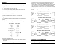
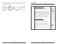
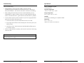
FCC Radio Frequency Interference Statement iMcV-DS3/E3/STS Repeater Operation Manual This equipment has been tested and found to comply with the limits for a Class A computing device, pursuant to Part 15 of the FCC Rules. These limits are designed to provide reasonable protection against harmful interference when the equipment is operated in a commercial environment. This equipment generates, uses and can radiate radio frequency energy and, if not installed and used in accordance with the instruction manual, may cause harmful interference to radio communications. Operation of this equipment in a residential area is likely to cause harmful interference in which the user will be required to correct the interference at his own expense. Any changes or modifications not expressly approved by the manufacturer could void the user’s authority to operate the equipment. The use of non-shielded I/O cables may not guarantee compliance with FCC RFI limits. This digital apparatus does not exceed the Class A limits for radio noise emission from digital apparatus set out in the Radio Interference Regulation of the Canadian Department of Communications. Le présent appareil numérique n’émet pas de bruits radioélectriques dépassant les limites applicables aux appareils numériques de classe A prescrites dans le Règlement sur le brouillage radioélectrique publié par le ministère des Communications du Canada. Limited Lifetime Warranty Effective for products of B&B Electronics shipped on or after May 1, 2013, B&B Electronics warrants that each such product shall be free from defects in material and workmanship for its lifetime. This limited lifetime warranty is applicable solely to the original user and is not transferable. This warranty is expressly conditioned upon proper storage, installation, connection, operation and maintenance of products in accordance with their written specifications. Pursuant to the warranty, within the warranty period, B&B Electronics, at its option will: 1. Replace the product with a functional equivalent; 2. Repair the product; or 3. Provide a partial refund of purchase price based on a depreciated value. Products of other manufacturers sold by B&B Electronics are not subject to any warranty or indemnity offered by B&B Electronics, but may be subject to the warranties of the other manufacturers. Notwithstanding the foregoing, under no circumstances shall B&B Electronics have any warranty obligations or any other liability for: (i) any defects resulting from wear and tear, accident, improper use by the buyer or use by any third party except in accordance with the written instructions or advice of the B&B Electronics or the manufacturer of the products, including without limitation surge and overvoltage conditions that exceed specified ratings, (ii) any products which have been adjusted, modified or repaired by any party other than B&B Electronics or (iii) any descriptions, illustrations, figures as to performance, drawings and particulars of weights and dimensions contained in the B&B Electronics’ catalogs, price lists, marketing materials or elsewhere since they are merely intended to represent a general idea of the products and do not form part of this price quote and do not constitute a warranty of any kind, whether express or implied, as to any of the B&B Electronics’ products. THE REPAIR OR REPLACEMENT OF THE DEFECTIVE ITEMS IN ACCORDANCE WITH THE EXPRESS WARRANTY SET FORTH ABOVE IS B&B ELECTRONIC’ SOLE OBLIGATION UNDER THIS WARRANTY. THE WARRANTY CONTAINED IN THIS SECTION SHALL EXTEND TO THE ORIGINAL USER ONLY, IS IN LIEU OF ANY AND ALL OTHER WARRANTIES, EXPRESS OR IMPLIED, AND ALL SUCH WARRANTIES AND INDEMNITIES ARE EXPRESSLY DISCLAIMED, INCLUDING WITHOUT LIMITATION (I) THE IMPLIED WARRANTIES OF FITNESS FOR A PARTICULAR PURPOSE AND OF MERCHANTABILITY AND (II) ANY WARRANTY THAT THE PRODUCTS ARE DO NOT INFRINGE OR VIOLATE THE INTELLECTUAL PROPERTY RIGHTS OF ANY THIRD PARTY. IN NO EVENT SHALL B&B ELECTRONICS BE LIABLE FOR LOSS OF BUSINESS, LOSS OF USE OR OF DATA INTERRUPTION OF BUSINESS, LOST PROFITS OR GOODWILL OR OTHER SPECIAL, INCIDENTAL, EXEMPLARY OR CONSEQUENTIAL DAMAGES. B&B ELECTRONIC SHALL DISREGARD AND NOT BE BOUND BY ANY REPRESENTATIONS, WARRANTIES OR INDEMNITIES MADE BY ANY OTHER PERSON, INCLUDING WITHOUT LIMITATION EMPLOYEES, DISTRIBUTORS, RESELLERS OR DEALERS OF B&B ELECTRONIC WHICH ARE INCONSISTENT WITH THE WARRANTY, SET FORTH ABOVE. ii Table of Contents About the iMcV-DS3/E3/STS FCC Radio Frequency Interference Statement .................................................... ii Limited Lifetime Warranty .................................................................................. ii About the iMcV-DS3/E3/STS ..............................................................................1 Installating an iMcV-DS3/E3/STS.........................................................................1 Configuration Instructions ..................................................................................1 Requirements.....................................................................................................1 DIP Switches ......................................................................................................3 LED Operation .................................................................................................11 Troubleshooting ...............................................................................................12 Specifications ...................................................................................................13 B&B Electronics Technical Support ...................................................................14 Fiber Optic Cleaning Guidelines.......................................................................15 Electrostatic Discharge Precautions ...................................................................16 Safety Certifications ..........................................................................................17 iMcV-DS3/E3/STS is an SNMP-manageable module which converts thin coax signals to single-mode or multi-mode fiber signals at a data rate of 45 Mbps (DS3), 34 Mbps (E3) or 52 Mbps (STS). Each iMcV-DS3/E3/STS, BNC/FX module includes one pair of BNC connectors and one pair of ST or SC fiber optic connectors. This module must be installed in either, an SNMP-manageable iMediaChassis chassis or an unmanaged MediaChassis chassis. Also available for single-strand fiber, iMcV-DS3/E3/STS, BNC/SSFX includes one pair of BNC connectors and an SC fiber optic connector. iMcV-DS3/E3/STS, BNC/SSFX modules allow two wavelengths, for example, (1310 nm and 1550 nm) to share one fiber strand, essentially doubling the capacity of installed fiber. iMcV-DS3/E3/STS modules must be deployed in pairs (one at each end of a conversion). The data transmitted on the fiber ports can only be received and interpreted by the receive fiber of another iMcV-DS3/E3/STS. The single strand versions must have opposite transmit and receive wavelengths (for example one that transmits at 1310 nm must be paired with another that receives at 1550 nm). Installating an iMcV-DS3/E3/STS iMcV-DS3/E3/STS modules can be installed in any iMediaChassis, MediaChassis or IEMediaChassis series (remote modules can also be installed in any unmanaged MediaChassis series or managed iMediaChassis series). Each module requires one slot in the chassis. To install a module, remove the blank brackets covering the slots where the module is to be installed (if present) by removing the screws on the outside edges of the bracket. Slide the module into the chassis card guides, until the module is securely seated in the connector. Secure the module to the chassis by tightening the captive screw. Save any blanks removed during installation for future use. Configuration Instructions Proper configuration of the iMcV-DS3/E3/STS is required for maximum performance and reliability. The following sections describe the prerequisites and the configurations available for both managed and unmanaged modules. Requirements The iMcV-DS3/E3/STS is designed to conform to many DS3/E3/STS-based environments. Make sure that all of the relevant information about the expected installation environment is available before configuring the module. This information includes the following: • Distance of the coax run • Distance of the fiber run • Troubleshooting requirements. iii 1 Managed Modules Unmanaged Modules To manage iMcV-DS3/E3/STS modules, an SNMP agent must be present; the iMediaChassis requires an SNMP management module. For a managed environment, first manually configure all of the desired DIP Switch selectable features to match what will be configured through the SNMP Management Module. Before installing the module in an unmanaged chassis, including IE-MediaChassis series and MediaChassis series, manually configure all of the desired DIP Switch selectable features. In an unmanaged configuration, none of the DIP Switch settings can be overridden by software. Use the Graphical User Interface (GUI) to enable features by using the iView2 SNMP management software. In a managed chassis, the software settings take priority over the SNMP enabled feature DIP Switch settings. Make sure that the software settings match the desired configuration requirements for the installation. NOTE Before installing the modules, they must be configured for Host/Remote via the DIP Switches. The Master/Slave condition requires this configuration: DIP Switches The iMcV-DS3/E3/STS DIP Switches are located on S1 and S2 on the PCB. The S2 DIP Switches are factory configured and must not be moved. The S1 DIP Switches provide control over the available iMcV-DS3/E3/STS features. The location of the S1 DIP Switches is displayed in the following diagram: S1-10: ON Remote Unit Enabled (only at the REMOTE end) (Remote) S1-10: OFF Remote Unit Disabled (only at the LOCAL end) (Host) iView² Management Software iView² is the B&B Electronics management software designed specifically for the B&B Electronics “iMcV” family of modules. It features a GUI and gives network managers the ability to monitor and control the manageable B&B Electronics products. iView² is available in several versions, including WebServer version 3.0, and can also function as a snap-in module for HP OpenView Network Node Manager and other third party SNMP Management software. iView2 supports the following platforms: Windows 2000 Windows XP Windows Vista Windows 7 Please see the SNMP Management Module installation guide for software configuration options. 2 3 Loopback Type FUNCTION SWITCH SETTINGS This switch controls which data line is looped back when the Loopback DIP Switch is enabled. The data line loopback selection can be either Fiber Loopback or Coax Loopback. RESULT [(D) = Default] 2 Loopback (iView Configurable) S1-1: OFF S1-1: ON Loopback Type (iView2 Configurable) S1-2: OFF S1-2: ON Jitter Attenuation (iView2 Configurable) S1-3: OFF S1-3: ON FiberAlert (iView2 Configurable) S1-4: OFF S1-4: ON Line Build-Out (iView2 Configurable) S1-5: OFF S1-5: ON Transmit Data Source (iView2 Configurable) S1-6: ON 7: ON S1-6: OFF 7: ON S1-6: ON 7: OFF S1-6: OFF 7: OFF DS3/E3/STS Selection S1-8: ON 9: OFF S1-8: OFF 9: ON S1-8: ON 9: ON Remote Unit S1-10: OFF S1-10: ON By default this feature is set to COAX. Loopback Disabled (D) Loopback Enabled This feature can be controlled by SNMP management software (iView2) when the iMcV-DS3/E3/STS module is installed in a managed chassis. Coax (D) Fiber Jitter Attenuation Jitter Attenuator on Receive Side Jitter Attenuator on Transmit Side (D) FiberAlert Disabled (D) FiberAlert Enabled This switch selects the jitter attenuation location on the coax transceiver. The jitter attenuation can be set on the transmit side or on the receive side of the coax transceiver. Jitter attenuation is useful for decreasing jitter in the coax data stream. This helps prevent data degradation caused by jitter. Jitter attenuation is always enabled. 0 to 255 ft. > 255 ft. (D) By default this feature is set to TRANSMIT. Standard Data (D) Unframed All Ones Alternating Ones & Zeros Pseudorandom Bit Sequence 45 Mbps (DS3) 34 Mbps (E3) 52 Mbps (STS) This feature can be controlled by SNMP management software (iView2) when the iMcV-DS3/E3/STS module is installed in a managed chassis. FiberAlert This switch enables or disables the FiberAlert feature. This feature must only be enabled on the remote end of a Host/Remote iMcV-DS3/E3/STS pair. Remote Unit Disabled (D) Remote Unit Enabled Feature Descriptions The iMcV-DS3/E3/STS module includes several features that allow it to be configured for varying DS3/E3/STS-based environments. The FiberAlert feature uses the iMcV-DS3/E3/STS module LEDs to indicate that a loss of one strand of fiber has occurred. When a strand becomes unavailable, the iMcVDS3/E3/STS module at the receiver-end detects the loss of the link. The module then responds by stopping the transmission of the data and link signal until a new signal or link pulse is received on the strand. The result is that the NO LNK LED on both sides of the fiber connection will light up to indicate the presence of a fault somewhere in the fiber loop. By using FiberAlert, a local site administrator can quickly determine wh3ere a fiber cable fault is located. Loopback By default this feature is set to DISABLED. This switch enables or disables the loopback feature. When this feature is enabled, the data line (Coax or Fiber) set by the Loopback Type DIP Switch is looped back. This feature can be controlled by SNMP management software (iView2) when the iMcV-DS3/E3/STS module is installed in a managed chassis. By default this feature is set to DISABLED. ** WARNING ** 2 This feature can be controlled by SNMP management software (iView ) when the iMcV-DS3/E3/STS module is installed in a managed chassis. 4 Enabling FiberAlert on both of the iMcV-DS3/E3/STS modules will cause them both to stop transmitting unrecoverably when a fault occurs. This feature is designed to only be enabled on the Remote iMcV-DS3/E3/STS module. 5 Transmit LIU Waveshape (Line Build-Out) This switch selects the optimal transmit waveshape for the line build-out distance on the coax line. The transmit waveshape can be set for a distance of either 0 to 255 feet or over 255 feet. This feature corrects problems related to cabling (i.e. cross-talk, electromagnetic interference, etc.). Improperly setting this switch will cause signal degradation. By default this feature is set to > 255 FEET. This feature can be controlled by SNMP management software (iView2) when the iMcV-DS3/E3/STS module is installed in a managed chassis. DS3, E3 and STS Selection This switch selects the data rate to use on the coax line. The data rate selections available include the following: • • • 45 Mbps (DS3) 34 Mbps (E3) 52 Mbps (STS) By default this feature is set to 45 Mbps (DS3). This feature can only be selected by setting the DIP Switches manually. Transmit Data Source These switches select the transmit mode used by the iMcV-DS3/E3/STS module. The transmit modes that can be selected include the following: • • • • Standard data Unframed All Ones (diagnostic) Alternating Ones and Zeros (diagnostic) Pseudorandom bit sequence (diagnostic) These standard Telco transmission pattern modes are provided to help diagnose transmission errors in the line. By default this feature is set to STANDARD DATA. This feature can be controlled by SNMP management software (iView2) when the iMcV-DS3/E3/STS module is installed in a managed chassis. 6 7 Remote Unit This option allows the user to enable Remote Unit on the module. The Remote Unit feature is designed to work only as the remote module of the Local/Remote pair in the required Master/Slave configuration. With Remote Unit enabled, the user can easily perform the following: • Test the line integrity of the remote copper port. • Use the Local unit to configure all SNMP-configurable features for both units. • Use the Local unit to download firmware for both units. Loopback testing is useful for troubleshooting problems with network connections should they occur. Looping received data back onto the transmit path helps determine whether a connection is still valid. Remote loopback tests isolate problems on the coax run between an iMcV-DS3/E3/STS module and the connected device, while local loopback tests can isolate problems on the fiber connected to the module. The following illustrations show a typical progression of loopback tests (i.e. starting by checking the coax segment at the local side, then the coax segment at the remote side, etc). Refer to the Module LED Functions section for more information. By default this feature is set to Disabled. This feature can only be selected by setting the DIP Switches manually. Loopback Testing The iMcV-DS3/E3/STS includes two loopback test modes: Coax Loopback and Fiber Loopback. The following illustrations show the path that a signal takes in each of the loopback test modes. Each loopback performs the following: • Redirects the incoming signal back out to the origin while continuing to transmit downstream. • Blocks downstream data from arriving on the looped data line. 8 Pseudorandom Bit Sequence (PRBS) Testing To test using Pseudorandom Bit Sequence, configure the iMcV-DS3/E3/STS modules for No Loopback, then configure the Transmit Data Source to “Transmit 9 Pseudorandom Bit Sequence.” Configure the local device for loopback, conduct the test, then check the PBEO LED to verify errors were not received (Refer to the LED section for more information). LED Operation The iMcV-DS3/E3/STS module features several diagnostic LEDs per port. The LED functions are as follows: LEDs Next to Coax (BNC) Port LPBK Glows green when module is in a Loopback mode. NO LNK Glows green when a link is NOT established. PBEO When Transmit Data Source is set to Pseudo-random Bit Sequence, this LED will glow yellow when iMcVDS3/E3/STS receives a Pseudorandom Bit Sequence with errors. The LED stays off when the converter receives a Pseudorandom Bit Sequence without errors. When Transmit Data Source is set to any other configuration besides Pseudorandom Bit Sequence, this LED remains off as well. LEDs Next to Fiber Optic Port Glows green when FiberAlert is enabled. FA NO LNK RM SYM 10 Glows green when a link is NOT established. Glows green on the Remote Unit when set to DSW S110. Glows green on the Local unit when it has discovered a Remote management with Remote Unit enabled. Glows yellow when a FX symbol error has occurred. 11 Troubleshooting Specifications General Troubleshooting Power Consumption (Typical) 0.550 Amps @ 5 V • During installation, first test the fiber and BNC connections with all troubleshooting features disabled; then enable these features, if desired, just before final installation. This will reduce the features’ interference with testing. • When working with units where the features cannot be disabled, you must establish BOTH your BNC and fiber connections; the NO LNK LEDs should not be lit (i.e. NO LNK LED not lit = good connection, NO LNK LED lit = problem). • To test a media converter by itself, first make sure you have an appropriate fiber patch cable, then follow these steps to test: 1. Connect the media converter to the BNC device with a coax cable. 2. Loop a single strand of fiber from the transmit port to the receive port of your media converter. Operating Temperature +32°F to +122°F (0°C to +50°C) Storage Temperature 0°F to +160°F (-20°C to +70 C) Humidity 5 to 95% (non-condensing); 0 to 10,000 ft. altitude Dimensions 4.19” x .78” x 2.75” (106.4 mm x 19.81 mm x 69.85 mm) 3. Verify that you have a valid connection for both the BNC and fiber ports on your media converter. • If there is trouble with link connectivity, make sure the connection is made using 75W Coax cable. NOTE iMcV-DS3/E3/STS Repeater modules cannot be connected iMcV-DS3/E3/STS LineTerm modules successfully. 12 13 B&B Electronics Technical Support Fiber Optic Cleaning Guidelines Tel: (800) 346-3119 (in the U.S. and Canada) Monday-Friday, 7:00am-7”00pm CST +353 91 792444 (Europe) Monday through Friday 8:00am - 5:00pm GMT Fiber Optic transmitters and receivers are extremely susceptible to contamination by particles of dirt or dust, which can obstruct the optic path and cause performance degradation. Good system performance requires clean optics and connector ferrules. 1. Use fiber patch cords (or connectors, if you terminate your own fiber) only from a reputable supplier; low-quality components can cause many hard-to-diagnose problems in an installation. 2. Dust caps are installed at B&B Electronics to ensure factory-clean optical devices. These protective caps should not be removed until the moment of connecting the fiber cable to the device. Should it be necessary to disconnect the fiber device, reinstall the protective dust caps. 3. Store spare caps in a dust-free environment such as a sealed plastic bag or box so that when reinstalled they do not introduce any contamination to the optics. 4. If you suspect that the optics have been contaminated, alternate between blasting with clean, dry, compressed air and flushing with methanol to remove particles of dirt. Fax: (815) 433-5109 U.S. and Canada +353 91-79244S5 Europe E-Mail: [email protected] U.S. and Canada [email protected] Europe Web: www.bb-elec.com 14 15 Electrostatic Discharge Precautions Safety Certifications Electrostatic discharge (ESD) can cause damage to any product, add-in modules or stand alone units, containing electronic components. Always observe the following precautions when installing or handling these kinds of products UL/CUL: Listed to Safety of Information Technology Equipment, including Electrical Business Equipment. 1. Do not remove unit from its protective packaging until ready to install. 2. Wear an ESD wrist grounding strap before handling any module or component. If the wrist strap is not available, maintain grounded contact with the system unit throughout any procedure requiring ESD protection. 3. Hold the units by the edges; do not touch the electronic components or gold connectors. 4. After removal, always place the boards on a grounded, static-free surface, ESD pad or in a proper ESD bag. Do not slide the modules or stand alone units over any surface. WARNING! Integrated circuits and fiber optic components are extremely susceptible to electrostatic discharge damage. Do not handle these components directly unless you are a qualified service technician and use tools and techniques that conform to accepted industry practices. 16 Class 1 Laser product, Luokan 1 Laserlaite, Laser Klasse 1, Appareil A’Laser de Classe 1 European Directive 2002/96/EC (WEEE) requires that any equipment that bears this symbol on product or packaging must not be disposed of with unsorted municipal waste. This symbol indicates that the equipment should be disposed of separately from regular household waste. It is the consumer’s responsibility to dispose of this and all equipment so marked through designated collection facilities appointed by government or local authorities. Following these steps through proper disposal and recycling will help prevent potential negative consequences to the environment and human health. For more detailed information about proper disposal, please contact local authorities, waste disposal services, or the point of purchase for this equipment. 17 International Headquarters B&B Electronics 707 Dayton Road Ottawa, IL 61350 USA Phone (815) 433-5100 — General Fax (815) 433-5105 Email: [email protected] Website: www.bb-elec.com European Headquarters B&B Electronics Westlink Commercial Park Oranmore, Co. Galway, Ireland Phone +353 91-792444 — Fax +353 91-79244S5 Email: [email protected] Website: www.bb-elec.com The information in this document is subject to change without notice. B&B Electronics assumes no responsibility for any errors that may appear in this document. iMcV-DS3/E3/STS Repeater is a trademark of B&B Electronics. Other brands or product names may be trademarks and are the property of their respective companies. Document Number 50-80301-00 A5 October 2013