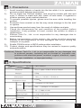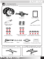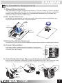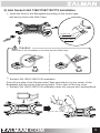
1
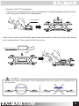
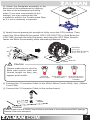
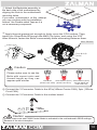
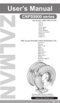
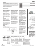
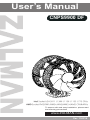
User’s Manual
CNPS9900 DF
Intel Socket LGA 2011 / 1366 / 1156 / 1155 / 775 CPUs
AMD Socket FM2/FM1/AM3+/AM3/AM2+/AM2 CPU&APUs
To ensure safe and easy installation, please read
the following precautions
www.ZALMAN.com
Ver. 130214
1. Precautions
1)
Avoid inserting objects or hands into the fan while it is in operation to
prevent product damage and injuries.
2) Do not ingest the Thermal Grease, and avoid its contact with skin and
eyes. If contact is made with skin, wash off with water. If ingested or
irritation persists, seek medical attention.
3) To prevent possible injuries, gloves must be worn while handling this
product.
4) Excessive force exerted on the fan may cause damage to the fan and/
or system.
5) Use and keep product away from the reach of children and pets.
6) Check the components list and condition of the product before
installation. If any problem is found, contact the retailer to obtain a
replacement.
7) Zalman Tech Co., Ltd. is not responsible for any damages due to
overclocking.
8) Before transportation of the system, the cooler must be removed.
Zalman is not responsible for any damages that occur during the
transport of a system.
9) Enable PWM function in BIOS settings after installation.
10) Product design and specifications may be revised to improve quality
and performance.
Disclaimer) Zalman Tech Co., Ltd. is not responsible for any damages due
to external causes, including but not limited to, improper use,
problems with electrical power, accident, neglect, alteration, repair,
improper installation, or improper testing.
2. Specifications
Model
Spec.
CNPS9900DF
Meterial
Pure Copper & Black Nickel Plated
Weight
850g
140(L) x 110(W) x 154(H) ㎜
Dimension
Dissipation Area
6,800㎠
Front 120mm
1,000rpm ±10% (3pin)
Center 140mm
900 ~ 1,400rpm ±10%(4pin)
RPM
Fan
Thermal Grease
[ZM-STG2]
Noise Level
19 ~ 27dBA ±10%
Bearing Type
Long Life Bearing
Contents
3.5g
Temperature Range
-40°C ~ +150°C (-40℉ ~ +302℉)
.COM
1
3. Components
1) Common Components
Cooler
Backplate
User’s Manual
Thermal Grease
[ZM-STG2]
Side Caps
Allen Wrench (3/32")
Gold Bolts
Silver Bolts A (4mm)
(Socket LGA 1366)
Y-Connector Cable
(Socket LGA 2011)
Nuts
2) Intel Components
Socket LGA 2011/1366/1156/1155/775
Intel Clip
.COM
Silver Bolts B (3mm)
(Socket AMD/LGA 1156/1155/775)
Loading Block Double-sided Tape
3) AMD Components
Socket FM2/FM1/AM3+/AM3/AM2+/AM2
AMD Clip
2
4. Installation Requirements
1) Space Requirements
The installation requires unobstructed space of 110mm (width) x 140mm (length)
x 154mm (height) with the CPU as the central reference point. Before installation,
please check if memory modules or motherboard heatsinks will not have any
clearance issues with the CPU cooler.
2) Air Guide Removal
Air guides on enclosures must be removed, before the cooler’s installation, for
they protrude into the cooler’s required space.
110㎜
154㎜
140㎜
3) Protective Brace Removal
Please unclip and remove the heatsink's plastic brace before installing the cooler.
4) Cooler Orientation
Orient the cooler so that the thinner heatsink is facing the
rear exhaust fan, while the thicker heatsink is facing the front
case fan (see right image).
5) Fan Protection Pad Removal & Cooler Handling
Remove the fan protection pad before you begin the installation process. Also, due to the sharp
heatsink fins, wearing gloves while handling the heatsink fins is strongly recommended.
.COM
3
5. Installation
A. Intel Socket Installation ( Go to Page 8 For AMD Sockets)
Partially unscrew the four bolts located on the base of the CPU cooler. Then,
insert the Intel Clips between the base and the heatpipe cover, with the clips
bent away from the heatsink.
Base
Intel Clip
Heatpipe cover
The holes in the Clip (as shown below) are
matched to the “keys” on the heatpipe cover
for secure Clip installation.
Insert
Key
1) Intel Socket 2011 Installation
Apply thermal grease just enough to thinly cover the CPU surface. Then, insert four Silver
Bolts (type A) through the outermost Intel Clip holes, and using the 3/32” Allen Wrench,
fasten the Silver Bolts incrementally while alternating between them.
Allen Wrench
Sliver Bolt A
(4mm)
Caution
Please make sure to use the
Bolts with correct color and
thread length as they can
appear quite similar.
Gold Bolts
Sliver Bolts A (4mm) Sliver Bolts B (3mm)
(Socket LGA 1366) (Socket LGA 2011) (Socket AMD/LGA1156/
1155/775/)
.COM
4
2) Intel Socket LGA 1366/1156/1155/775 Installation
① Insert the Nuts to the Backplate according to the socket type
and secure them with Side Caps.
Socket 775
Socket 1156/1155
2
Socket 1366
1
Caution
O
X
Take note of the orientation of the Nuts and the Side Caps.
② Socket LGA 1366/1156/1155 Installation
Peel off one side of the Double-sided Tape and attach it to the center of the
Backplate with the sticky side facing down. Then, peel off the top cover.
※ Socket LGA 1366/1156/1155 Installation does not require the Loading Block.
.COM
5
③S
ocket LGA 775 Installation
Peel off the Loading Block cover and attach it to the Backplate with the sticky
side facing the center of the Backplate.
Loading Block
Peel off one side of the Double-sided Tape and attach it with the sticky side facing
the Loading block. Then, peel off the top cover.
Double-sided Tape
Caution
O
X
Please note that the sticky side of the Loading Block serves to attach the Loading Block to
the backplate.
.COM
6
④ Attach the Backplate assembly to the
back side of the motherboard by aligning
the Nuts to the motherboard mounting
holes. If you were unsuccessful at first
attempt, you may continue with the
installation without the Double-sided Tape
as it is not a necessary component.
M/B
⑤ Apply thermal grease just enough to thinly cover the CPU surface. Then,
insert four Silver Bolts B (for socket LGA 1156/1155/775) or Gold Bolts (for
LGA 1366) through the Intel Clip holes, and using the 3/32” Allen Wrench,
fasten the Bolts incrementally while alternating between them.
Gold Bolt
(Socket 1366)
Sliver Bolt B (3mm)
(Socket 1156/1155/775)
M/B
Wrench
Caution
Please make sure to use the
Bolts with correct color and
thread length as they can
appear quite similar.
Gold Bolts
(Socket 1366)
Sliver Bolts A (4mm) Sliver Bolts B (3mm)
(Socket 2011)
(Socket 1156/1155/
775/AMD)
⑥ Connect the Y-Connector Cable to the 4Pin(140mm Center FAN), 3pin (120mm
Front FAN) .
⑦ Connect the Y-Connector Cable to the mother board.
M/B
Caution
Please make sure that PWM Control Mode is activated in the motherboard’s BIOS settings.
Beware of fan wire interuption
.COM
7
B. AMD Socket Installation
1) AMD Socket FM2/FM1/AM3+/AM3/AM2+/AM2 Installation
①P
artially unscrew the four bolts located on the base of the CPU cooler.
Then, insert the AMD Clips between the base and the heatpipe cover, with
the clips bent away from the heatsink.
Base
AMD Clip
Heatpipe cover
The holes in the Clip (as shown
below) are matched to the “keys” on
the heatpipe cover for secure Clip
installation.
Insert
Key
② Insert the Nuts to the Backplate according to the socket type and secure
them with Side Caps.
2
1
Caution
O
X
Take note of the orientation of the Nuts and the Side Caps.
.COM
8
③Peel off the Loading Block cover and attach it to the Backplate with the
sticky side facing the center of the Backplate.
Loading Block
Peel off one side of the Double-sided Tape and attach it with the sticky side facing
the Loading block. Then, peel off the top cover.
Double-sided Tape
Caution
O
X
Please note that the sticky side of the Loading Block serves to attach the Loading Block to
the backplate.
the CPU cooler retention bracket on the motherboard by unscrewing the four bolts
④Dismantle
M
/B
located at each corner (method may vary; consult the motherboard manual for details).
Be sure to keep the retention bracket so the stock CPU cooler can be used as a backup.
B
M/
.COM
9
M
/B
⑤ Attach the Backplate assembly to
the back side of the motherboard by
aligning the Nuts to the motherboard
mounting holes.
If you were unsuccessful at first attempt,
you may continue with the installation
without the Double-sided Tape as it is
not a necessary component.
⑥ Apply thermal grease just enough to thinly cover the CPU surface. Then,
insert four Silver Bolts B through the AMD Clip holes, and using the 3/23"
Allen Wrench, fasten the Bolts incrementally while alternating between them.
Allen Wrench
M
/B
Silver Bolt B
(3mm)
Caution
Please make sure to use the
Bolts with correct color and
thread length as they can
appear quite similar.
Gold Bolts
Sliver Bolts A (4mm) Sliver Bolts B (3mm)
(Socket LGA 1366) (Socket LGA 2011)
(Socket AMD/LGA
1156/1155/775)
⑥ Connect the Y-Connector Cable to the 4Pin(140mm Center FAN), 3pin (120mm
Front FAN) .
⑦ Connect the Y-Connector Cable to the mother board.
M/B
Caution
Please make sure that PWM Control Mode is activated in the motherboard’s BIOS settings.
Beware of fan wire interuption
.COM
10