1
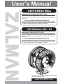
User’s Manual
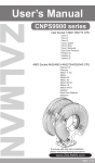
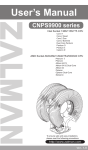
CNPS9900 Max
Intel Socket 2011/1366/1156/1155/775 CPU
Core i7 Extreme, Core i7, Core i5, Core i3, Core 2 Extreme, Core
2 Quad, Core 2 Duo, Pentium Dual-Core, Pentium D, Pentium 4,
Celeron D
AMD Socket FM1/AM3+/AM3/AM2+/AM2 CPU
Zambezi, Llano, Phenom II, Phenom, Athlon II, Athlon X2, Athlon
FX, Athlon, Opteron Dual-Core, Opteron, Sempron
CNPS9900A LED / NT
Intel Socket 1366/1156/1155/775 CPU
Core i7 Extreme, Core i7, Core i5, Core i3, Core 2 Extreme, Core
2 Quad, Core 2 Duo, Pentium Dual-Core, Pentium D, Pentium 4,
Celeron D
AMD Socket FM1/AM3+/AM3/AM2+/AM2 CPU
Zambezi, Llano, Phenom II, Phenom, Athlon II, Athlon X2, Athlon
FX, Athlon, Opteron Dual-Core, Opteron, Sempron
To ensure safe and easy installation, please read
the following precautions
www.ZALMAN.com
Ver. 3.0
1. Precautions
1)
Avoid inserting objects or hands into the fan while it is in operation to
prevent product damage and injuries.
Do not ingest the Thermal Grease, and avoid its contact with skin and
eyes. If contact is made with skin, wash off with water. If ingested or
irritation persists, seek medical attention.
To prevent possible injuries, gloves must be worn while handling this
product.
Excessive force exerted on the fan may cause damage to the fan and/
or system.
Use and keep product away from the reach of children and pets.
Check the components list and condition of the product before
installation. If any problem is found, contact the retailer to obtain a
replacement.
Zalman Tech Co., Ltd. is not responsible for any damages due to
overclocking.
Before transportation of the system, the cooler must be removed.
Zalman is not responsible for any damages that occur during the
transport of a system.
Enable PWM function in BIOS settings after installation.
Product design and specifications may be revised to improve quality
and performance.
2)
3)
4)
5)
6)
7)
8)
9)
10)
Disclaimer) Zalman Tech Co., Ltd. is not responsible for any damages due
to external causes, including but not limited to, improper use,
problems with electrical power, accident, neglect, alteration, repair,
improper installation, or improper testing.
6SHFL¿FDWLRQV
AcXY`
GdYW"
AUhYf]U`
7BDG--$$5@98
DifY7cddYf
KY][\h
7BDG--$$A5L
6@I9#F98
DifY7cddYf 6`UW_!DYUf`B]W_Y`D`UhYX
+'$[
+))[
8]aYbg]cbg
-(@Ṋ%'%KṊ%)&<ỻ
<YUh8]gg]dUh]cb5fYU
) ($&Wa 6YUf]b[
:Ub
7BDG--$$BH
Ei]YhAcXY
Ok#FYg]ghYfQ
BcfaU`AcXY
Ok#cFYg]ghYfQ
H\YfaU`;fYUgY
ONA!GH;&Q
&6U``!6YUf]b[
@cb[@]ZY6YUf]b[
FDA
,$$r%'$$fda᳗%$
-$$r%)$$fda᳗%$
Bc]gY@YjY`
%,r&,")X65᳗%$
%,r&+X65᳗%$
FDA
%$$$r&)$$fda᳗%$
-$$r%+$$fda᳗%$
Bc]gY@YjY`
%-")r',"$X65᳗%$
%,r'$X65᳗%$
7UdUW]hm
'")[
HYad"FUb[Y
!($᳢r%)$᳢!($r'$&ᴬ
.COM
1
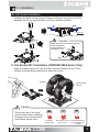
3. Components
1) Common Components
Cooler
User’s Manual
Backplate
Thermal Grease
[ZM-STG2]
Side Caps
Resistor
Wrench
Gold Bolts
Silver Bolts A (4mm)
Silver Bolts B (3mm)
(Socket 1366 )
(Socket 2011,
CNPS9900MAX Only)
(Socket 1156/1155/775/AMD)
Nuts
Loading Block
2) Intel Components
CNPS9900 MAX : Socket 2011/1366/1156/1155/775
CNPS9900ALED/NT : Socket 1366/1156/1155/775
Intel Clip
.COM
Double-sided Tape
3) AMD Components
Socket FM1/AM3+/AM3/AM2+/AM2
AMD Clip
2
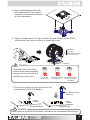
("=bghU``Uh]cbFYei]fYaYbhg
1) Space Requirements
The cooler’s installation requires unobstructed space with dimensions of
133mm(width), 96mm(length), 154mm(height), and the CPU as a central
reference point. Please check if components such as ODDs and PSU protrude
into the required space.
2) Air Guide Removal
Air guides on enclosures must be removed, before the cooler’s installation, for
they protrude into the cooler’s required space.
-*ỻ
%)(ỻ
%''ỻ
3) Protective Brace Removal
Please unclip and remove the heatsink’s Plastic Brace before installing the cooler.
4) Cooler Orientation
In relation to the cooler’s centrally located fan,
DLUÀRZVIURPWKH³WKLQQHU´IURQWKHDWVLQNWRWKH
³WKLFNHU´UHDUKHDWVLQN$VVKRZQLQWKHGLDJUDP
below, it is recommended that the cooler be
LQVWDOOHGVRWKDWDLUÀRZVIURPWKHFRROHUWRZDUG
the enclosure’s rear exhaust fan to be released.
5) Cooler Handling
Please hold the cooler with both
hands as shown in the diagram.
.COM
3
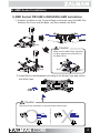
5. Installation
A. Intel Socket Installation
!Unfasten the Bolts on the Cooler’s Base one thread, insert the Intel Clip
between the Cover and the Base, and then refasten the Bolts.
Intel Clip
Caution
Make sure the Intel Clip’s ingresses
DUHÀXVKDJDLQVW
the protrusions of
the Base Cover.
Align
1) Intel Socket 2011 Installation (CNPS9900 MAX Series Only)
- Apply a suitable amount of the included Thermal Grease on the CPU’s
surface and then fasten the Bolts to install the cooler.
Wrench
Sliver Bolt A
(4mm)
Caution
Check the size of the silvercolored bolts before installing
because silver-colored bolt A
and B have similar color.
Gold Bolts
(Socket 1366)
.COM
Sliver Bolts A (4mm) Sliver Bolts B (3mm)
(Socket 2011)
(Socket 1156/1155/
775/AMD)
4
2) Intel Socket 1366/1156/1155/775 Installation
ᾒInstall Bolts to the Backplate according to the Socket Type and secure
with Side Caps.
Socket 775
Socket 1156/1155
&
Socket 1366
%
Caution
Take note of the orientation of the Nuts and the Side Caps.
O
X
ᾓSocket 1366/1156/1155 Installation
Attach Double-sided Tape to the center of the Backplate and remove
the Double-sided Tape’s Cover.
ᳱSocket 1366/1156/1155 Installation does not require the Loading Block.
.COM
5
ᾔSocket 775 Installation
Remove the Sticker Cover from the Lower Tier of the Loading Block and
attach to the Backplate.
Loading Block
Attach Double-sided Tape to the Loading Block and remove the Double-sided
Tape Cover.
Double-sided Tape
Caution
Please make note of the orientation of the Loading Block’s Installation.
O
.COM
X
6
ᾕAlign the Backplate’s Nuts with
the motherboard’s Clip Support
installation holes and then fasten
to the motherboard.
M/B
ᾖApply a suitable amount of the included Thermal Grease on the CPU’s
surface and then fasten the Bolts to install the cooler.
Gold Bolt
(Socket 1366)
Sliver Bolt B (3mm)
(Socket 1156/1155/775)
M/B
Wrench
Caution
Check the size of the silvercolored bolts before installing
because silver-colored bolt A
and B have similar color.
Gold Bolts
(Socket 1366)
Sliver Bolts A (4mm) Sliver Bolts B (3mm)
(Socket 2011)
(Socket 1156/1155/
775/AMD)
ᾗConnect the cooler’s 4-pin connector to the
motherboard’s CPU Fan header.
Fan RPM-reducing
resistance
M/B
<Normal Mode>
M/B
<Quiet Mode>
Caution
Please make sure that PWM Control Mode is activated in the motherboard’s BIOS settings.
.COM
7
B. AMD Socket Installation
1) AMD Socket FM1/AM3+/AM3/AM2+/AM2 Installation
ᾒUnfasten the Bolts on the Cooler’s Base one thread, insert the AMD Clip
between the Cover and the Base, and then refasten the Bolts.
5A87`]d
Caution
Make sure the AMD Clip’s ingresses
DUHÀXVKDJDLQVWWKHSURWUXVLRQVRI
the Base Cover.
Align
ᾓInstall Bolts to the Backplate according to the Socket Type and secure
with Side Caps.
&
%
Caution
Take note of the orientation of the Nuts and the Side Caps.
O
.COM
X
8
ᾔRemove the Sticker Cover from the Lower Tier of the Loading Block
and attach to the Backplate.
Loading Block
Attach Double-sided Tape to the Loading Block and remove
the Double-sided Tape Cover.
Double-sided Tape
Caution
Please make note of the orientation of the Loading Block’s Installation.
O
X
A
#6
ᾕDisassemble the motherboard’s Clip Support.
6
A#
.COM
9
A
#6
ᾖAlign the Backplate’s Nuts
with the motherboard’s
Clip Support’s installation holes
and fasten to the motherboard.
ᾗApply a suitable amount of the included Thermal Grease on the CPU’s
surface and then fasten the Silver Bolts to install the cooler.
(Please use the designated Bolts in accordance with Socket Types.)
G]`jYf6c`h6
'aa
Wrench
A#6
Caution
Check the size of the silvercolored bolts before installing
because silver-colored bolt A
and B have similar color.
Gold Bolts
(Socket 1366)
Sliver Bolts A (4mm) Sliver Bolts B (3mm)
(Socket 2011)
(Socket 1156/1155/
775/AMD)
ᾘConnect the cooler’s 4-pin connector to the
motherboard’s CPU Fan header.
Fan RPM-reducing
resistance
M/B
<Normal Mode>
M/B
<Quiet Mode>
Caution
Please make sure that PWM Control Mode is activated in the motherboard’s BIOS settings.
.COM
10