1
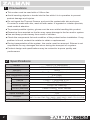
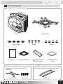
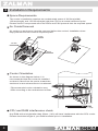
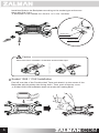
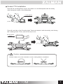
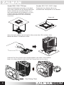
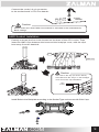
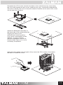
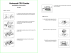
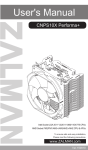
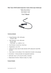
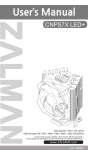
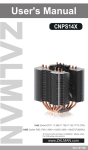
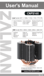
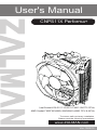
User's Manual
CNPS11X Performa+
Intel Socket LGA 2011 V3/2011/1366/115X/775 CPUs
AMD Socket FM2/FM1/AM3+/AM3/AM2+/AM2 CPU & APUs
To ensure safe and easy installation,
Please read the following precautions.
www.ZALMAN.com
Ver.150810
1 Precautions
■ This cooler must be used with a 120mm fan.
■ Avoid inserting objects or hands into the fan while it is in operation to prevent
product damage and injuries.
■ Do not ingest the Thermal Grease, and avoid its contact with skin and eyes.
If contact is made with skin, wash off with water. If ingested or irritation persists,
seek medical attention.
■ To prevent possible injuries, gloves must be worn while handling this product.
■ Excessive force exerted on the fan may cause damage to the fan and/or system.
■ Use and keep product away from reach of children.
■ Check the components list and condition of the product before installation. If any
problem is found, contact the retailer to obtain a replacement.
■ During transportation of the system, the cooler must be removed. Zalman is not
responsible for any damages that occur during the transport of a system.
■ Product design and specifications may be revised to improve quality and
performance.
2 Specifications
2
Model
Dimensions
Weight
Material
Heat Dissipation Area
Dimension
Speed
Fan
Noise Level
Bearing Type
Control Method
Connector
Input Voltage
CNPS11X Performa+
132(L) X 94.5(W) X 153.5(H)mm
450g
Pure Copper and Aluminum
5,310cm²
Ø120 x 25(H)mm
1,000 – 1,600RPM ±10%
17 - 26dBA ±10%
Long Life Bearing
PWM Control, Auto Restart
4Pin
12V
Socket
Intel Socket LGA 2011 V3/2011/1366/115X/775 CPUs
AMD Socket FM2/FM1/AM3+/AM3/AM2+/AM2 CPU & APUs
Thermal Grease
ZM-STG2M(ver2)
.COM
3 Components
Common Components
Cooler
Backplate
Side Caps
Bolts
Th
Nuts
er
Manual
Loaging Block
Intel Components
al
G
re
as
e
Thermal Grease
[ZM-STG2M]
Double-sided
Tape
AMD Components
- Socket LGA 2011 V3/2011/1366/115X/775
- Stand off
Intel Clip
m
Stand-off
.COM
Socket FM2/FM1/AM3+/AM3/AM2+/AM2
AMD Clip
3
4 Installation Requirements
Space Requirements
The cooler’s installation requires an unobstructed space of 94.5mm(width)
132mm(length) and 153.5mm(height) with the CPU as a central reference point.
Please check if components such as ODDs and PSU protrude into the required space.
Air Guide Removal
Air guides on enclosures must be removed before the cooler’s installation since
they protrude into the cooler’s required space.
94.5㎜
153.5㎜
132㎜
Cooler Orientation
As shown in the diagram below, it is
recommended that the cooler be installed
so that air flows from the cooler toward the
enclosure’s rear exhaust fan to be released.
* Recommended cooler orientation may
differ according to the motherboard model.
CPU and RAM interference check
Any RAM with a height taller than 36mm (1.42) will have interference with the CPU cooler.
Please check the height of your RAM modules prior to installation.
4
.COM
5 Installation
LGA Intel Socket Installation
Intel Socket 2011 V3 / 2011 User
Partially unscrew the four bolts located on the base of the CPU cooler. Then insert
the Intel Clips between the base and the heatpipe cover, with the clips bent away
from the heatsink.
Intel Clip
Caution
The holes in the Clip (as shown below)
are matched to the “keys” on the heatpipe
cover for secure Clip installation.
Key
Insert
Intel Socket 1366 / 115X / 775 User
Partially unscrew the four bolts located on the base of the CPU cooler. Then, insert
the Intel Clips between the base and the heatpipe cover, with the clips bent away
from the heatsink.
Intel Clip
Caution
The holes in the Clip (as shown below)
are matched to the “keys” on the
heatpipe cover for secure
Clip installation.
Key
Insert
.COM
5
Install the Bolts to the Backplate according to the socket type and secure
them with Side Caps.
※ Backplate is not needed for LGA 2011 V3 / 2011 sockets.
Socket 775
2
Socket 115X
Socket 1366
1
Caution
O
X
Take note of the orientation of the Nuts and the Side Caps.
Socket 1366 / 115X Installation
Peel off one side of the Double-sided Tape and attach it to the center of the
Backplate with the sticky side facing down. Then, peel off the top cover.
※ Socket 1366/115X Installation does not require the Loading Block.
6
.COM
Socket 775 Installation
Peel off the Loading Block cover and attach it to the Backplate with the sticky
side facing the center of the Backplate.
Loading Block
Peel off one side of the Double-sided Tape and attach it with the sticky side facing
the Loading block. Then, peel off the top cover.
Double-sided
Tape
Caution
O
X
Please make note of the orientation of the Loading Block’s Installation.
.COM
7
Socket 1366 / 115X / 775 User
Socket 2011 V3 / 2011 User
Attach the Backplate assembly to the back
side of the motherboard by aligning the Nuts
to the motherboard mounting holes. If you
were unsuccessful at first attempt, you may
continue with the installation without the
Fasten the four Stand-offs to the
motherboard. Backplate is not needed.
Double-sided Tape as it is not a necessary
component.
Stand-off
M/B
M/B
Apply thermal grease just enough to thinly cover the CPU surface, then
fasten the Bolts to isntall the cooler.
Latch the Fan Fixing Clips to the notches located on the sides of the heatsink.
Note: It is often easier to latch the Fan Fixing Clips one at a time.
Fan Fixing Clips
8
.COM
Connect the cooler’s 4-pin connector
to the motherboard’s CPU Fan header.
M/B
Caution
Please make sure that PWM Control Mode is activated in the motherboard’s
BIOS settings.
AMD Socket Installation
artially unscrew the four bolts located on the base of the CPU cooler. Then,
P
insert the AMD Clips between the base and the heatpipe cover, with the clips
bent away from the heatsink.
AMD Clip
Caution
The holes in the Clip (as shown below)
are matched to the “keys” on the heatpipe
cover for secure Clip installation.
Key
Insert
Install Bolts to the Backplate according to the Socket Type and secure with Side Caps.
2
1
.COM
9
Caution
O
X
Take note of the orientation of the Nuts and the Side Caps.
Peel off the Loading Block cover and attach it to the Backplate with the sticky
side facing the center of the Backplate.
Loading Block
Peel off one side of the Double-sided Tape and attach it with the sticky side facing
the Loading block. Then, peel off the top cover.
Double-sided
Tape
Caution
O
X
Please make note of the orientation of the Loading Block’s Installation.
10
.COM
M
/B
Attach the Backplate assembly to
the back side of the motherboard by
aligning the Nuts to the
motherboard mounting holes.
If you were unsuccessful at first
attempt, you may continue
with the installation without the
Double-sided Tape as it is not a
necessary component.
M
M/B
/B
Dismantle the CPU cooler retention bracket on the motherboard by unscrewing
the four bolts located at each corner (method may vary; consult the motherboard
manual for details). Be sure to keep the retention bracket so the stock CPU cooler
can be used as a backup.
Apply thermal grease just enough to thinly cover the CPU surface, then fasten
the Bolts to isntall the cooler.
.COM
11
Latch the Fan Fixing Clips to the notches located on the sides of the heatsink.
Note: It is often easier to latch the Fan Fixing Clips one at a time.
Fan Fixing Clips
Connect the cooler’s 4-pin connector to the
motherboard’s CPU Fan header.
M/B
Caution
Please make sure that PWM Control Mode is activated in the motherboard’s
BIOS settings.
12
.COM