1
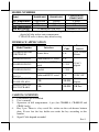
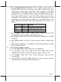
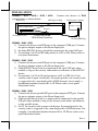
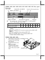
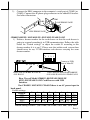
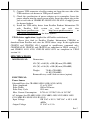
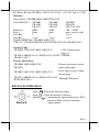
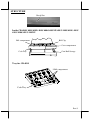
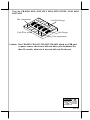
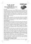
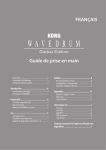
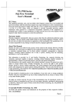
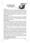
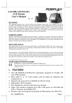
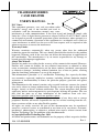
CR-4000/6000 SERIES
CASH DRAWER
USER’S MANUAL
Rev. B0
FCC Notes:
This equipment generates, uses, and can radiate radio
frequency energy and, if not installed and used in
accordance with the instructions manual, may cause
interference to radio communications. It has been tested and found to comply with
limits for a Class A digital device pursuant to subpart J of Part 15 of FCC Rules, which
are designed to provide reasonable protection against interference when operated in a
commercial environment. Operation of this equipment in a residential area is likely to
cause interference in which case the user at his own expense will be required to take
whatever measures to correct the interference.
Warranty Limits:
Warranty terminates automatically when any person other than the authorized
technicians opens the machine. The user should consult his/her dealer for the problem
happened. Warranty voids if the user does not follow the instructions in application of
this merchandise. The manufacturer is by no means responsible for any damage or
hazard caused by improper application.
About This Manual:
Posiflex has made every effort for the accuracy of the content in this manual. However,
Posiflex will assume no liability for any technical inaccuracies or editorial or other
errors or omissions contained herein, nor for direct, indirect, incidental, consequential
or otherwise damages, including without limitation loss of data or profits, resulting
from the furnishing, performance, or use of this material.
This information is provided “as is” and Posiflex Technology, Inc. expressly disclaims
any warranties, expressed, implied or statutory, including without limitation implied
warranties of merchantability or fitness for particular purpose, good title and against
infringement.
The information in this manual contains only essential hardware concerns for general
user and is subject to change without notice. Posiflex reserves the right to alter product
designs, layouts or drivers without notification. The system integrator shall provide
applicative notices and arrangement for special options utilizing this product. The user
may find the most up to date information of the hardware from web sites:
http://www.posiflex.com or http://www.posiflex.com.tw
All data should be backed-up prior to the installation of any drive unit or storage
peripheral. Posiflex will not be responsible for any loss of data resulting from the use,
disuse or misuse of this or any other Posiflex product.
All rights are strictly reserved. No part of this documentation may be reproduced,
stored in a retrieval system, or transmitted in any form or by any means, electronic,
mechanical, photocopying, or otherwise, without prior express written consent from
Posiflex Technology, Inc. the publisher of this documentation.
© Copyright Posiflex Technology Inc. 2011
All brand and product names and trademarks are the property of their respective holders.
P/N: 19240901050
Part 1
MODEL NUMBERS
CR421X/4225/
CR6015/621X
5 Fixed
5 Fixed
Bill Compartment 5 Adjustable
Plastic
Metal
Metal
Bill clip
9 Fixed
9 Fixed
5 Fixed
Coin compartment
1 Underneath Cash Tray
4 Behind Cash Tray
Coin Roll storage
Note: 1. CR-4020 series is a special model having 9 bill compartments with
plastic bill clip and no coin compartment
2. CR-621X series is heavy duty metal casing
Model
CR400X/4015
CR410X/4115
INFERFACE APPLICATION
Model Number
Interface
Security
Code
Power /
Source
CR-4000/4020/4100/
4210/CR-6210
Printer drive
N. A.
CR-4001/4101/4211
Dedicated RS232 serial
N. A.
CR-4002/4102/4212
Non-dedicated RS232
serial
0 ~ 255
CR-4003/4103/4213
Parallel
0 ~ 255
Dedicated RS232 serial
N. A.
12VDC / PC
USB
USB PID
12VAC /
Adaptor
USB
USB PID USB Port
CR-4004/4104/4214
CR-6214
CR-4005-II/4105-II
/4215-II/ CR- 6215
CR-4015/ CR-4115/
CR-4225/CR-6015
12/24 V Pulse
/ Printer
12VAC /
Adaptor
CARTON CONTENTS
1.
2.
3.
4.
5.
Cash drawer pre-assembled.
User’s manual.
Separators of bill compartment: 4 pcs (for CR4000~4, CR4005-II and
CR4015 only).
Key 2 pcs: There is a key serial No. sticker on the cash drawer bottom
plate. If user lost the key he/she can order the key according to this
number.
Signal Cable depend on model
Part 2
a). For CR4000/4020/4100/4210/6210: The standard signal cable is
21863018010 which has a 8 pin plug at one end to connect to the cash
drawer and a 6 pin plug at the other end to connect to the POS
system/printer. This cable serves for most popularly used POS
equipment such as all Posiflex POS terminals, all Posiflex POS printers,
most Epson POS printers, most Star POS printers and all other
compatibles. The user may cut the 6 pin end and assemble this free end
according to his POS printer specification if the POS printer used
utilizes different connection. The cable connection on the wires is as
below:
RJ45 Function
Wire color
Red
Pin 1 Drawer open sense
Blue
Pin 2 Drawer open sense return
Green
Pin 7 + 24V to solenoid
Yellow
Pin 8 Drawer kick pulse
b). For CR4001/ 4101/ 4211/ 4002/ 4102/ 4212: 21863137210
/21863237210 with one 9PM and one 9PF connector.
c). For CR4003/ 4103/ 4213: 21863231810 with one 25PM and one 25PF
connector.
d). For CR4004/ 4104/ 4214/ 6214: The serial signal cable is already built
on.
e). For CR-4015/ 4005-II/ 4115/ 4105-II/ 4215-II/ 4225/ 6015/ 6215: USB
cable is already built on.
6. Power Source depend on model
a). For CR-4000/ 4020/ 4100/ 4210/ 6210: not applicable
b). For CR-4001/ 4101/ 4211/ 4002/ 4102/ 4212/ 4003/ 4103/ 4213/
CR4005-II / 4105-II/ 4215-II/ 6215: Power adapter 12VAC 1.5A
c). For CR4004/ 4104/ 4214/ 6214: Power connector cable and I/O
bracket plate.
d). For CR-4015/ 4115/ 4225/ 6015: There is no power adaptor needed,
the power source drain from USB port directly.
Part 3
INSTALLATION
CR4000 / 4020 / 4100 / 4210 / 6210
Connect the drawer to POS
system/printer
as
shown
below:
Rear View
8P Telephone Plug
POS System or Printer
Output to drawer
Control signal input
Ground
8P Telephone Jack
CASH DRAWER
With Printer Interface
6P Telephone Plug
CR4001 / 4101 / 4211
1). Connect the drawer serial I/P port to the computer COM port. Connect
the power adapter output to the Power Input jack
2). No other RS232C devices should be connected to the serial O/P port.
3). Set position 3 of S2 to OFF and position 4 of S2 to ON. Please refer to
rear panel illustration.
CR4002 / 4102 / 4212
1). Connect the drawer serial I/P port to the computer COM port. Connect
the power adapter output to the Power Input jack.
2). Other RS232C device can be connected to the serial O/P port when
needed as long as the security code makes no influence to this RS232C
device.
3). Set position 3 of S2 to ON and position 4 of S2 to OFF. Set S1 for
security code to open cash drawer. In normal practice, the security code
is suggested to be a non-displayable ASCII character, for example, a
hexadecimal number between 01 to 1F. Please refer to rear panel
illustration below.
CR4003 / 4103 / 4213
1). Connect the drawer parallel I/P port to the computer LPT port. Connect
the power adapter output to the Power Input jack.
2). Other parallel device such as a printer can be connected to the parallel
O/P port when needed as long as the Security code makes no influence
to this parallel device.
3). Set S1 for security code to open cash drawer. In normal practice, the
security code is suggested to be a non-displayable ASCII character. For.
example, a hexadecimal number between 01 to 1F. Please refer to rear
panel illustration below.
Part 4
CR4001/ 4101/ 4211/ 4002/ 4102/ 4212/ 4003/ 4103/ 4213 Rear panel
illustration.
AC 12V I/P
PARALLEL O/P (DB25F)
Switch is ON when pushed up
SERIAL O/P (DB9M)
S1
8
SERIAL I/P (DB9F)
S1
S2
14 1
PARALLEL I/P (DB25M)
GROUND
Set security code. (Default Setting: BIT 1,2,3 OFF and BIT
4,5,6,7,8 ON. Security code is 07H)
BIT
1
2
3
4
5
6
7
8
Number to be added to the
1
2
4
8 16 32 64 128
security code if OFF.
S2 BIT1 ON and BIT2 OFF to receive security code via Pin2 of P4
(DB9F).
BIT1 OFF and BIT2 ON* to receive security code via Pin3 of P4
(DB9F).
BIT3 OFF and BIT4 ON for dedicated RS-232C.
BIT3 ON and BIT4 OFF* for non-dedicated RS-232C.
(* denotes factory default setting)
CR4004 / 4104 / 4214 / 6214
1). Open the PC case. Put the 616P PHONE JACK
metal bracket with power
connector into one of the
I/O windows.
2). Connect the cable to the
HDD type power
connector of PC power
supply. See illustration
below. Then close the PC
POWER CORD
case.
Part 5
3).
Connect the DB-9 connector to the computer's serial port of COM1 (or
COM2). Connect the 4P phone plug connector to the added I/O bracket.
See below illustration.
COM1
DB9
616P PHONE JACK
4PIN PHONE JACK
CR4015/ 4005-II / 4115/ 4105-II / 4225/ 4215-II / 6015/ 6215
1). Define a drawer number for the cash drawer so that this cash drawer is
going to respond accordingly in USB communication. Follow the table
below for “Switch settings” to adjust the switch S1 according to this
drawer number if it is not 7. Please note that within each system there
should never be any 2 USB interface cash drawers carrying the same
drawer number.
O
N4
AC 12V I/P
3 2 1
Connect to USB
Port of Main PC
S1
Ground
Power Jack of CR4005-II/ 4105-II/
4215-II/6215
USB Connector from CR4015/4005-II/
4115/ 4105-II/ 4225/4215-II/ 6015/ 6215
Rear View of Model CR4015/ 4005-II/ 4115/4105-II/
4225/ 4215-II/ 6015/ 6215 Cash Drawer with USB
Interface
For CR-4015/ 4115/ 4225/ CR-6015 there is no AC power input in
back panel.
Switch settings:
0
1
2
3
4
5
6
Drawer
7
ON OFF ON OFF ON OFF ON OFF
SW1
ON ON OFF OFF ON ON OFF OFF
SW2
ON ON ON ON OFF OFF OFF OFF
SW3
ON: Vendor Class
OFF : HID Class
SW4
Default setting: Drawer 7 (SW1: OFF; SW2: OFF; SW3: OFF; SW4: OFF)
Part 6
2). Connect USB connector of cable coming out from the rear side of the
USB interface cash drawer to USB port of main PC.
3). Check the specification of power adaptor on its nameplate. Insert the
power adaptor into the correct power outlet. Insert the output plug to the
jack at rear side of CR4005-II/ 4105-II/ 4215-II/ 6215 to supply power
for drawer kickout.
4). Install the USB utility driver from Posiflex Product Information CD
with Posiflex POS system or visit our
web sites
http://www.posiflex.com
or
http://www.posiflex.com.tw
or
http://www.posiflexusa.com for latest updates.
UPOS driver application (Applied for all Posiflex cash drawer)
Please first find in Posiflex Product Information CDROM or
download from Posiflex web sites for UPOS driver setup. In this application
CR4XX3 and CR4XX4/ 6214 respond to openDrawer command only;
CR4XX0/ 6210, CR4XX1 and CR4XX2 are compliant to UPOS version 1.7
and CR4015/ 4115/ 4225/ 4XX5-II/ 6015/ 6215 are compliant to UPOS
version 1.8.
SPECIFICATIONS
MECHANICAL:
Dimensions:
428 (W) x 460 (D) x 100 (H) mm (CR-4000)
428 (W) x 456 (D) x 100 (H) mm (CR-6000)
Weight:
7.0 Kg (CR-4000)
8.8 Kg (CR-6000)
Removable tray with a lock-on cover (option)
ELECTRICAL:
Power Source
Solenoid Drive (for CR-4000 / 4020 / 4100 / 4210 / 6210)
Pulse Amplitude
12 to 24 VDC
Pulse Width
100 to 250 msec
Pulse Duty Cycle
10% max.
Max. Current Consumption
0.75A @ 12 VDC/1.5A @ 24 VDC
AC Adaptor (for CR-4001/ 4101/ 4211/ 4002/ 4102/ 4212/ 4003/ 4103/
4213/ 4005-II/ 4105-II/ 4215-II/ 6215)
Input Voltage
120 VAC ± 10 % / 240 VAC ± 10 % @50
-60 Hz
Output Voltage
12 VAC at 1.5 A
Part 7
DC Power Kit (for CR-4004 / 4104 / 4214 / 6214): +12 V DC and + 5 V DC
Interface
Direct Drive: CR-4000/ 4020/ 4100/ 4210/ 6210
Serial (RS232C): CR-4001
CR-4002
CR-4004
CR-4101
CR-4102
CR-4104
CR-4211
CR-4212
CR-4214/ 6214
Baud rate
9600
9600
150 ~ 19200
Parity
None
none
none, even, or odd
Data Bits
8
8
7 or 8
Stop Bits
1 or 2
1 or 2
1 or 2
Parallel (IEEE1284): CR-4003/ 4103/ 4213
USB (1.1): CR-4015/ 4005-II/ 4115/ 4105-II/ 4225/ 4215-II/ 6015/ 6215
Security Code
CR-4002/ 4102/ 4212/ 4003/ 4103/ 4213
1-255; factory preset
value = 7
CR-4015/ 4005-II/ 4115/ 4105-II/ 4225/ 4215-II USB PID
CR-6015 / 6215
Drawer Open Sense
CR-4000/ 4020/ 4100/ 4210
CR-6210
Drawer open sense circuit
shorts when open
CR-4001/ 4101/ 4211/ 4002/ 4102/ 4212
Pin 9 shorts to pin 5 when
drawer open
CR-4015/ 4005-II/ 4115/ 4105-II/ 4225/ 4215Through USB driver
II/ CR-6015/ 6215
KEYLOCK OPERATION
Keylock
Lock (
): Physically lock the drawer.
Open (
): Open the drawer by the key.
Standby (
): Automatically open the drawer by POS
printer or POS system or interface
signal control
Part 8
STRUCTURE
Check Slot
Inside CR-4000/ 4001/ 4002/ 4003/ 4004/ 4005-II/ 4015/ 4100/ 4101/ 4102/
4103/ 4104/ 4115/ 4105-II
Bill compartment
Bill Clip
Coin compartment
Cash Tray
Coin Roll Storage
Tray for CR-4020
9 Bill compartment
Cash Tray
Part 9
Tray for CR-4210/ 4211/ 4212/ 4213/ 4214/ 4225/ 4215-II / 6210/ 6214/
6015/ 6215
Bill compartment
Cash Tray
Coin Roll Storage
Bill Weight
Coin compartment
Caution : For CR-4015/ CR-4115/ CR-4225 /CR-6015 which use USB port
as power source; the drawer kick out duty cycle should not less
then 15 seconds, otherwise it may not kick out the drawer.
警告使用者
T31454
這是甲類的資訊產品,在居住的環
境中使用時,可能會造成射頻干
擾,在這種情況下,使用者會被要
求採取某些適當的對策。
Part 10