1
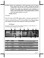
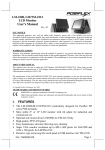
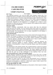
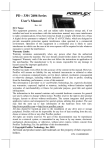
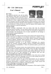
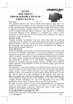
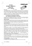
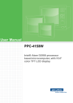
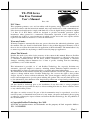
TX-3700 Series
Fan Free Terminal
User’s Manual
Rev.: A0
FCC Notes:
This equipment generates, uses, and can radiate radio frequency energy and, if not installed and
used in accordance with the instructions manual, may cause interference to radio communications.
It has been tested and found to comply with limits for a Class A digital device pursuant to subpart
J of Part 15 of FCC Rules, which are designed to provide reasonable protection against
interference when operated in a commercial environment. Operation of this equipment in a
residential area is likely to cause interference in which case the user at his owns expense will be
required to take whatever measures to correct the interference.
Warranty Limits:
Warranty terminates automatically when any person other than the authorized technicians opens
the machine. The user should consult his/her dealer for the problem happened. Warranty voids if
the user does not follow the instructions in application of this merchandise. The manufacturer is by
no means responsible for any damage or hazard caused by improper application.
About This Manual:
Posiflex has made every effort for the accuracy of the content in this manual. However, Posiflex
Technology, Inc. will assume no liability for any technical inaccuracies or editorial or other errors
or omissions contained herein, nor for direct, indirect, incidental, consequential or otherwise
damages, including without limitation loss of data or profits, resulting from the furnishing,
performance, or use of this material.
This information is provided “as is” and Posiflex Technology, Inc. expressly disclaims any
warranties, expressed, implied or statutory, including without limitation implied warranties of
merchantability or fitness for particular purpose, good title and against infringement.
The information in this manual contains only essential hardware concerns for general user and is
subject to change without notice. Posiflex Technology, Inc. reserves the right to alter product
designs, layouts or drivers without notification. The system integrator shall provide applicative
notices and arrangement for special options utilizing this product. The user may find the most up
to date information of the hardware from: http://www.posiflex.com or http://www.posiflex.com.tw
or http://www.posiflexusa.com
All data should be backed-up prior to the installation of any drive unit or storage peripheral.
Posiflex will not be responsible for any loss of data resulting from the use, disuse or misuse of this
or any other Posiflex product.
All rights are strictly reserved. No part of this documentation may be reproduced, stored in a
retrieval system, or transmitted in any form or by any means, electronic, mechanical, photocopying,
or otherwise, without prior express written consent from Posiflex Technology, Inc. the publisher of
this documentation.
© Copyright Posiflex Technology, Inc. 2012
All brand and product names and trademarks are the property of their respective holders.
P/N: 14510900020
Part 1
ALERT TO OUR HONORABLE CUSTOMERS:
Please always read thoroughly all the instructions and documents delivered
with the product before you do anything about it. Don’t take any premature
action before you have a full understanding of the consequences.
DAILY MAINTENANCE GUIDE
For regular cleaning of the TX systems, please use only soft haired brush or
dry soft cloth. You may use moist soft cloth to remove stains when necessary.
Apply only suitable amount of mild neutral cleaner for obstinate stains. Please
note that never use Acryl dissolving solvent or Polycarbonate dissolving
solvent. You may apply ammonia-based glass cleaner only on the screen
surface.
ABOUT THIS PRODUCT
Posiflex TX-3700 presents a whole new generation POS terminal which with
the most reliable Fan free system and carrying a brilliant performance to user
in order to face the busiest situation. This terminal applies Intel Cedar View
CPU technology; fast speed Ethernet as well as plenty of connects ports of
Power USB, USB, Serial, VGA and CR ports and designed with gorgeous
appearance and small footprint for counter space saving.
TX-3700 terminal can assist small and medium business to serve customer
effectively, fast and precise. This small and fully functional system is suitable
for various kinds of segments, such as general retailer, hospitality and
restaurant with very limit space.
Dual Core Intel Processor with 1M cache
Supports various operating systems
Supports Power USB with one 12V/1A and one +24V/2A port
CR port controlling up to 2 cash drawers.
Supports wall mount application and VESA 75mm standard.
Part 2
INTRODUCTION
Power Switch with
LED Indicators
I/O Panel
PRODUCT SPECIFICATIONS
Item
CPU
Chipset
VGA port
Memory
Serial port
VGA port
UPS port
CR port
USB
Power USB
LAN port
Storage
Power switch
Installation
Power saving
Power supply
LED
OS support
Description
INTEL Cedar view-D2550 1.86G, 1M Cache, Dual Core
Intel NM10
D-SUB 15Pin, supports +12V output
DDR3 1066, SO-DIMM x 1 , 1/2/4GB
1
COM1, COM2, COM3, COM4 (Optional)
2
COM1/2/3 supports +5V/+12V; COM4 supports +5V
Standard one VGA; VGA2 is optional1
12V BAT
1, controlling up to 2 cash drawers
USB0, USB1, USB2, USB3
+12V/1A X1, +24V/2A X1
10/100/1000 MB
2.5" SATA HDD or SSD (8GB up to 64GB)
Soft Switch
Desk Top or Wall Mount
Suspension mode
12V DC power adaptor, 120W
Power ON/ standby, bi-color LED,
Ethernet Link LED on Ethernet Connector
XP Pro, POSReady 7, Win 7, POSReady 2009, Linux
1
COM4 and VGA2 port can not co-exist, and must be specified on order.
2 +5V output configured by software settings; +12V output configured by jumper settings.
Part 3
Option Items:
Note: The underlined items in the following list means that option must be
set prior to shipment from the factory. The rest items can be set by the
dealers.
a)
b)
c)
d)
DDR3 memory expansion up to 4GB max.
Integrated upgrade kit: WB-6812 Wall mount bracket.
Preload OS Win XP Pro, Win 7, POS Ready 7, POSReady 2009, Linux
24V Power USB cable for compatible printer
INSTALLATION GUIDES
Hardware Power Switch
The power switch located in the front bezel of main unit.
It is a pushbutton switch and controls the power on/off
of the whole system.
This power switch turns the system on when pushed only. This switch turns
the system off when pushed again during power on status. However, if the
system hangs due to any reason such as software resource conflict, a simple
push on the switch in 10 sec may turn off the power.
Note: There must always be at least 10 seconds waiting before switching
on again once the system is powered off successfully.
LED Indicator for Power
Beside the Power switch is an LED indicator showing the
power status. The Power LED indicator’s behaviors are shown
in the following table.
LED Color
Orange
Blue
Description
Power supply is well connected. The terminal is on standby.
The terminal has been powered on.
Part 4
CAUTION: Before any installation or cable connection to the set, please
always make sure that the system is turned off and the
external power source to the set is removed to prevent electric
hazard! Never touch any metal pin in the connectors or
circuits to avoid high voltage hazard or electrostatic discharge
damage unless the operator is well grounded. Failure to do the
above will void the product warranty!
Display Issues
VGA Port
The VGA port on TX-3700 supports either a separately connected LCD
monitor or touch monitor. To support the DC power to the display monitor, it
required a qualified technician to set up through BIOS setting. Do not connect
other monitor to this port before the power in this port is disabled.
I/O Panel
I/O panel is on the rear side of the terminal and houses various I/O ports, as
described in the following figure and table.
A
Call out
A
B
C
D
E
F
G
H
I
B
D
C
E
Label
DC IN
COM1
COM2
VGA
COM3
USB0-3
PUSB 12V
PUSB 24V
LAN
F
G
I
H
J
K
Description
Connecting to 12V/150W power supply
Com port, connecting to peripherals
Com port, connecting to peripherals
Connecting primary display
Com port, connecting to peripherals
4 USB ports, connecting to USB devices
+12V Power USB
+24V Power USB
LAN port, connecting to Ethernet
Part 5
J
K
CR
VGA2 or
COM4
Controlling up to 2 cash drawers
Connecting to second display
Com port, connecting to peripherals
COM1/2/3/4 can supply a +5 V DC through system BIOS and jumper setting
and supply +12V by jumper setting. The VGA port can delivery +12 V power
through system BIOS setting for Posiflex LCD display monitor. Nevertheless,
except Posiflex peripheral device, do not connect any other device to this
port before the power in this port is disabled.
CAUTION: Please turn off the system power first! Then hold the base and
move the terminal carefully.
Connecting Cables
To have the terminal ready for operation, please connect all required cables to
the appropriate connectors. Please make sure that each connector is connected
to the correct port with the correct orientation. Damages due to incorrect
connection or orientation are not covered by product warranty!
Some connectors like the LAN or CR connector have to be gently inserted
until a click is heard. It is recommended that connectors such as the COM port
and VGA connector be screwed into place once seated. Please make sure that
each connector has to be connected to the right device in the right way.
CAUTION: On doing any insertion or extraction of any connector, please
always hold the connector head itself instead of pulling on the
cable wire. Failure to do this could damage the cable and jack
that is considered as an artificial destruction and is not
covered by the warranty.
Connecting Cash Drawer (Option)
The RJ11 connector on I/O panel can be used for controlling most of the
common cash drawers available on the market.
However, it is most recommended to use Posiflex CR-2000 or CR-2200 or
CR-3100 or CR-3200 or CR-4000 or CR-4100 or CR-4210 or CR-6310 for
best compliance to operate the opening mechanism and to monitor the drawer
open status.
Use the cable supplied with the cash drawer for connection to the CR port in
TX system. This cable has a 6-pole plug at one end and an 8-pole plug at the
Part 6
other. The 8-pole plug should be inserted into the connector marked: “signal
cable from POS Printer” at the rear of the cash drawer. The 6-pole plug should
be inserted in the connector marked “CR” found in the main connection area in
the system.
Wall Mount Application
The terminal can be mounted on wall with the VESA compliant
wall mount kit WB-6812. For installation step, please refer to the
WB-6812 installation guide.
System Recovery
A system recovery DVD would be shipped with the terminals that
preloaded with the chosen OS. The System Integrator shall take
care of software restoration after OS recovered. A Posiflex supplied USB
interface DVD drive will be required for such action. Other brand DVD-ROM
drive may require its own driver different from what supported in the recovery
DVD.
Please use the recovery DVD in system recovery only. Using it otherwise
may wipe out whatever stored in the storage device! All upgrade devices
drivers needed for manual installation in usual way are available in the
subfolder “\drivers” in OS recovered HDD and the latest versions of these
required drivers will be available on our web: http://www.posiflex.com. Then
follow instructions from your system integrator for software recovery.
APPLICATION ENVIRONMENT
It is very important that you check the following operational guidelines:
Ventilation
This terminal must NOT be operated in an environment with restricted
ventilation. There must be at least 25 mm air clearance around any top or side
ventilation holes with a free flow of air around the unit at ALL times for the
installation.
Part 7
Operating Environment
The equipment must not be operated or stored in extremes of both temperature
and humidity/moisture. (Operating range 0°C to 40°C and up to 80%
humidity – none condensing, max. wet bulb 26°C)
Power Supply
The operating voltage range of the power adaptor should cover the local power
supply for proper operation. The power cable, the power outlet and any power
fusing arrangements must conform to local safety regulations.
Please never do any connection / disconnection when system is still powered
on. Please always keep the external power adaptor in a free air circulation.
Automatic Power on Control
The system may also turn on according to some preset conditions such as
Alarm Clock Wake Up or LAN Wake Up.
When the TX system is turned off after a successful boot up, the preset
automatic power on functions will keep monitoring for the preset conditions
and turn on the system when the preset conditions are met.
Please notice that if the TX system is improperly turned off before a complete
boot up procedure, the above preset power on control functions will be
disabled until next turning off after a complete boot up.
Storage Device
The standard system storage device is 2.5” SATA HDD in the main unit. This
device can be replaced with an option SATA SSD HDD.
警告使用者
T31454
這是甲類的資訊產品,在居住的環
境中使用時,可能會造成射頻干
擾,在這種情況下,使用者會被要
求採取某些適當的對策。
Part 8