1
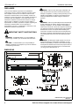
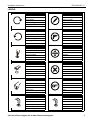
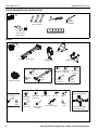
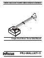
INSTALLATION INSTRUCTIONS
Instrucciones de instalación
Installationsanleitung
Instruções de Instalação
Istruzioni di installazione
Installatie-instructies
Instructions d´installation
Single Stud Short Throw Wall Mount
Spanish Product Description
German Product Description
Portuguese Product Description
Italian Product Description
Dutch Product Description
French Product Description
PRJ-WALLKIT-11
PRJ-WALLKIT-11
Installation Instructions
DISCLAIMER
InFocus and its affiliated corporations and subsidiaries
(collectively "InFocus"), intend to make this manual accurate
and complete. However, InFocus makes no claim that the
information contained herein covers all details, conditions or
variations, nor does it provide for every possible contingency in
connection with the installation or use of this product. The
information contained in this document is subject to change
without notice or obligation of any kind. InFocus makes no
representation of warranty, expressed or implied, regarding the
information contained herein. InFocus assumes no
responsibility for accuracy, completeness or sufficiency of the
information contained in this document.
IMPORTANT SAFETY INSTRUCTIONS
WARNING: Failure to read, thoroughly understand, and
follow all instructions can result in serious personal injury,
damage to equipment, or voiding of factory warranty! It is the
installer’s responsibility to make sure all components are
properly assembled and installed using the instructions
provided.
WARNING: Failure to provide adequate structural strength
for this component can result in serious personal injury or
damage to equipment! It is the installer’s responsibility to
make sure the structure to which this component is attached
can support five times the combined weight of all equipment.
Reinforce the structure as required before installing the
component. The wall to which the mount is being attached
may have a maximum drywall thickness of 5/8" (1.6cm). Do
not install drywall anchors into the seam between drywall
pieces.
WARNING: A WARNING alerts you to the possibility of
serious injury or death if you do not follow the instructions.
WARNING: Exceeding the weight capacity can result in
CAUTION: A CAUTION alerts you to the possibility of
damage or destruction of equipment if you do not follow the
corresponding instructions.
serious personal injury or damage to equipment! It is the
installer’s responsibility to make sure the combined weight of
all components attached to the short throw projector mounts
up to (and including) the projector does not exceed 25 lbs
(11.34 kg) for the PRJ-WALLKIT-11.
DIMENSIONS
32.78" MIN - 58.21" MAX
2.50
.328 TYP
TRAVEL 28 - 52.5"
.50
6.38
14.13
3 OF
LEVELING ADJUSTMENT
5.73
7.56
8.38
10.38
1.42
13.00
2.52
5.36
1.09
6.02
7.40
40.89
1.61
57.83
2.28
BOLT CIRCLE
55.37
2.18
40.89
1.61
5.63
.22
110.94
4.37
THREADS ONTO 1 1/2" NPT
168.48
6.63
YAW ADJUSTMENT POINT
10
128.88
5.07
PITCH ADJUSTMENT POINT
4
46.20
1.82
ROLL ADJUSTMENT POINT
4
DIMENSIONS: [MILLIMETERS]
INCHES
2
Visit the InFocus support site at www.infocus.com/support
Installation Instructions
PRJ-WALLKIT-11
LEGEND
Tighten Fastener
Pencil Mark
Apretar elemento de fijación
Marcar con lápiz
Befestigungsteil festziehen
Stiftmarkierung
Apertar fixador
Marcar com lápis
Serrare il fissaggio
Segno a matita
Bevestiging vastdraaien
Potloodmerkteken
Serrez les fixations
Marquage au crayon
Loosen Fastener
Drill Hole
Aflojar elemento de fijación
Perforar
Befestigungsteil lösen
Bohrloch
Desapertar fixador
Fazer furo
Allentare il fissaggio
Praticare un foro
Bevestiging losdraaien
Gat boren
Desserrez les fixations
Percez un trou
Phillips Screwdriver
Adjust
Destornillador Phillips
Ajustar
Kreuzschlitzschraubendreher
Einstellen
Chave de fendas Phillips
Ajustar
Cacciavite a stella
Regolare
Kruiskopschroevendraaier
Afstellen
Tournevis à pointe cruciforme
Ajuster
Open-Ended Wrench
Remove
Llave de boca
Quitar
Gabelschlüssel
Entfernen
Chave de bocas
Remover
Chiave a punte aperte
Rimuovere
Steeksleutel
Verwijderen
Clé à fourche
Retirez
By Hand
Optional
A mano
Opcional
Von Hand
Optional
Com a mão
Opcional
A mano
Opzionale
Met de hand
Optie
À la main
En option
Hex-Head Wrench
Security Wrench
Llave de cabeza hexagonal
Llave de seguridad
Sechskantschlüssel
Sicherheitsschlüssel
Chave de cabeça sextavada
Chave de segurança
Chiave esagonale
Chiave di sicurezza
Zeskantsleutel
Veiligheidssleutel
Clé à tête hexagonale
Clé de sécurité
Visit the InFocus support site at www.infocus.com/support
3
PRJ-WALLKIT-11
Installation Instructions
TOOLS REQUIRED FOR INSTALLATION
5/32"
(security)
[included]
#2
1/2" (12.7mm)
7/16" (11.2mm)
1/2" (12.7mm)
3/8" (9.5mm)
7/32" (5.6mm)
PARTS
C (1)
[Top cover]
A (1)
[Short throw wall mount]
J (2)
K (2)
L (4)
8-32 x 1/2" 1/4-20 x 1/2" 1/4-20 x 3/4"
(security) (security)
(security)
F (4)
1/4-20 x 1-3/4"
E (1)
[Projector mount]
P (4)
5/16 x 2-1/2"
Q (4)
5/16"
4
G (4)
1/4"
R (4)
1/4-20 x 3/8"
[not used]
W (4)
10-24 x 1-3/8"
H (4)
1/4-20
S (4)
10-24 x 3/8"
[not used]
D (1)
[Lower cover]
B (1)
[Wall bracket]
M (2)
10-24 x 1"
(security)
T (2)
5/16-18 x 1/2"
X (4)
1/4-20 x 1-1/2"
[not used]
U (2)
#8 x 1/2"
Y (4)
[Concrete anchor]
V (2)
#10 x 1"
N (1)
5/32"
(security)
AA (1)
[Universal interface]
Z (2)
5/16"
(Including hardware
and instructions)
Visit the InFocus support site at www.infocus.com/support
Installation Instructions
PRJ-WALLKIT-11
Site Requirements
WARNING: IMPROPER INSTALLATION CAN LEAD TO EQUIPMENT FALLING CAUSING SERIOUS PERSONAL INJURY
OR DAMAGE TO EQUIPMENT! The figure below identifies the minimum requirements for installation of display mounts onto a
steel stud structure. If the structure or its components do not meet these requirements contact the mount manufacturer for specific
instructions before attempting installation. It should also be noted that no other equipment should be mounted to the same stud.
16" or 24" (on center) Studs
Mount Installation Location
(Must be centered on stud)
If back side of wall is unfinished, drywall must be installed
to a minimum of one stud left and right of the stud(s)
being used to install the mount. Drywall must be
secured to studs with screws 12" on center
There must be a minimum of
1-7/8" (48mm) clearance
inside wall
FRONT
Drywall
**1/2" minimum
Drywall Thickness
(Both Sides of Stud)
**See hazard statement
on page 2!
Steel Stud (2 x 4 / 25ga minimum)
Stud type and structural strength must conform to the North American
Specification for the Design of Cold-Formed Steel Structural Members.
[362, 125 18, C-Shape, S-Stud Section]
Visit the InFocus support site at www.infocus.com/support
5
PRJ-WALLKIT-11
Installation Instructions
ASSEMBLY AND INSTALLATION
The single stud short throw wall mount can be mounted to
concrete, concrete block, 2" x 4" wood studs or steel studs.
(Y) x 4
4
Installing Mounting Bracket
(Q) x 4
WARNING: ELECTRICAL SHOCK HAZARD! CUTTING
OR DRILLING INTO ELECTRICAL CORDS OR CABLES
CAN CAUSE DEATH OR SERIOUS PERSONAL INJURY!
ALWAYS make certain area behind mounting surface is free
of electrical wires and cables before cutting, drilling, or
installing fasteners.
WARNING: EXPLOSION AND FIRE HAZARD! CUTTING
OR DRILLING INTO GAS PLUMBING CAN CAUSE DEATH
OR SERIOUS PERSONAL INJURY! ALWAYS make certain
area behind mounting surface is free of gas, water, waste, or
any other plumbing before cutting, drilling, or installing
fasteners.
5
(P) x 4
Mounting Wall Bracket
(B)
Concrete or Concrete Block
1.
Determine mounting location on wall.
2.
Using wall bracket (B) as a template, mark four holes at the
outer holes in bracket. (See Figure 1)
3.
Drill four 3/8" x 3-3/8" deep holes at marked locations in wall.
(See Figure 1)
Figure 2
Wood Studs
1.
Determine mounting location on wall. Use a stud finder to
locate studs.
2.
Line up inner three holes on wall bracket (B) with center of
stud at desired mounting location. (See Figure 3)
3.
Using wall bracket (B) as a template, mark three holes at
inner three holes in bracket. (See Figure 3)
4.
Drill three 7/32" x 2-1/2" deep holes at locations marked in
Step 3. (See Figure 3)
(front view)
(B)
(front view)
2
x4
wood stud
(B)
3
3
x3
4
Figure 1
4.
Install four concrete anchors (Y) into drilled holes. (See
Figure 2)
5.
Install four 5/16 x 2-1/2" hex head lag screws (P) through
four 5/16" washers (Q), outer holes of wall bracket (B) and
into concrete anchors (Y). (See Figure 2)
Figure 3
6
Visit the InFocus support site at www.infocus.com/support
Installation Instructions
5.
PRJ-WALLKIT-11
Install three 5/16 x 2-1/2" hex head lag screws (P) through
three 5/16" washers (Q), inner holes of wall bracket (B) and
into drilled holes. (See Figure 4)
5.
Hold metal channel on anchor (H) flat alongside plastic
straps and slide channel through hole. (See Figure 6)
Drywall
Plastic Straps
5
5
(P) x 3
(Q) x 3
(H) x 3
Figure 6
6.
Holding plastic straps on anchor (H), pull anchor away from
wall until channel rests flush behind wall making sure anchor
channel is positioned vertically on stud. (See Figure 7)
7.
Slide plastic cap on anchor (H) towards wall until flange of
cap is flush with wall. (See Figure 7)
(B)
(side view)
Steel Stud
Drywall
Figure 4
Steel Studs
Plastic Cap
IMPORTANT ! : See Site Requirements section before
proceeding with Steel Studs installation to ensure
installation site meets requirements! The drywall must
have a minimum thickness of 1/2"!
1.
6
Determine mounting location on wall. Use stud finder to
locate steel studs.
2.
Line up inner three holes on wall bracket (B) with center of
stud at desired mounting location. (See Figure 5)
3.
Using wall bracket (B) as a template, mark three holes at
inner three holes in bracket. (See Figure 5)
4.
Drill three 1/2" holes at marked locations in wall. (See
Figure 5)
7
(H) x 3
Anchor Metal Channel
Figure 7
8.
9.
Snap off plastic straps on anchor at wall by pushing side to
side, snapping off straps level with flange of plastic cap.
(See Figure 8)
Repeat Steps 5 through 8 for each mounting hole.
(B)
(side view)
3
Steel Stud
Drywall
8
Plastic Cap
x3
4
Plastic Straps
Steel stud
Anchor Metal Channel
Figure 5
Visit the InFocus support site at www.infocus.com/support
Figure 8
7
PRJ-WALLKIT-11
Installation Instructions
10. Place wall bracket (B) over anchors and align mounting
holes in display mount with holes in anchors. (See Figure 9)
11. Insert 1/4-20 x 1-3/4" Phillips pan head screws (F) through
1/4" washer (G), corresponding mounting hole on wall
bracket and into anchor (H) and tighten until flush against
mount. DO NOT overtighten! (See Figure 9)
1
(B)
Upper plate
1
12. Repeat Steps 10 through 11 for remaining 2 mounting
holes.
WARNING: IMPROPER INSTALLATION CAN LEAD TO
EQUIPMENT FALLING CAUSING SERIOUS PERSONAL
INJURY OR DAMAGE TO EQUIPMENT! Overtightening of
mounting hardware can damage the steel studs. DO NOT
overtighten mounting hardware!
(side view)
2
Steel Stud
Drywall
(G) x 3
11
Lower plate
(A)
(F) x 3
Figure 10
3.
Fasten wall mount assembly (A) to wall bracket (B) using
two 5/16-18 x 1/2" hex head cap screws (T) through two
5/16" washers (Z), the wall bracket and wall mount
assembly. (See Figure 11)
3
(T) x 2
(B)
Anchor Metal Channel
Figure 9
Installation to Wall Bracket
1.
Lift wall mount assembly (A) up to wall bracket (B) and hook
upper plate over upper notches on bracket. (See Figure 10)
2.
Slide lower plate into lower notches on bracket. (See
Figure 10)
(A)
(B)
(Z) x 2
Figure 11
8
Visit the InFocus support site at www.infocus.com/support
Installation Instructions
PRJ-WALLKIT-11
Projector Installation
Installing Mount Covers
1.
Raise lower cover (D) up to wall mount assembly. (See
Figure 12)
WARNING: Exceeding the weight capacity can result in
serious personal injury or damage to equipment! It is the
installer’s responsibility to make sure the combined weight of
all components attached to the short throw projector mounts
up to (and including) the projector does not exceed 25 lbs
(11.34 kg) for the PRJ-WALLKIT-11.
1
Holes for projector mount
(D)
Figure 12
2.
Lower top cover (C) onto wall mount assembly. (See
Figure 13)
3.
Install two #10 x 1" Phillips pan head tapping screws (V)
through holes on sides of covers. (See Figure 13)
4.
Install two #8 x 1/2" Phillips pan head tapping screws (U)
into top of top cover (C). (See Figure 13)
(bottom view)
Figure 14
Projector Mount Installation
3
4
(V) x 2
(U) x 2
1.
Line up mounting holes on projector mount (E) with
corresponding holes on mounting plate. (See Figure 14)
2.
Install four #10-24 x 1-3/8" Phillips pan machine screws (W)
through projector mount holes and into mounting plate.
(See Figure 15)
IMPORTANT ! : If projector mount is NOT installed in the
same direction as shown, ROLL adjustment screws will
be inaccessible! (See Figure 15)
2
(C)
Mounting plate
Roll adjustment screws
(E)
Figure 13
2
(W) x 4
Figure 15
Visit the InFocus support site at www.infocus.com/support
9
PRJ-WALLKIT-11
Installation Instructions
Projector Installation to Mount
7 Lock
WARNING: IMPROPER INSTALLATION CAN LEAD TO
6
Locking
lever
PROJECTOR FALLING RESULTING IN SERIOUS
PERSONAL INJURY OR DAMAGE TO EQUIPMENT. DO
NOT substitute hardware. Use only the hardware provided by
the manufacturer.
1.
Secure interface bracket (AA) to top of InFocus projector
(not included) using hardware and instructions included with
the interface bracket.
2.
Orient projector with attached interface bracket as shown.
(See Figure 16)
3.
Lift projector so that screws with thumb nuts are aligned
with mounting slots in mount base. (See Figure 16)
4.
Slide projector with interface bracket onto mounting slots in
projector mount (F) until screws are seated against the back
of mounting slots. (See Figure 16)
4
Thumb nuts
6
5
Mounting screw
with thumb nut
seated in
mounting slot
(reverse view)
3
Figure 17
(E)
(Interface appearance is example only.
Appearance may vary.)
Projector Mount Adjustments
Yaw Adjustment
1.
Loosen yaw adjustment locking screw using a #2 Phillips
screwdriver. (See Figure )
2.
Turn Yaw micro-adjustment screw right or left using a #2
Phillips screwdriver until image is properly aligned on target.
(See Figure )
3.
Tighten Yaw adjustment locking screw using a #2 Phillips
screwdriver. (See Figure )
1
Figure 16
3
WARNING: IMPROPER INSTALLATION CAN LEAD TO
PROJECTOR FALLING RESULTING IN SERIOUS
PERSONAL INJURY OR DAMAGE TO EQUIPMENT. Make
certain mounting slots in projector mount slide under thumb
screws and that screws are seated in the back of slots.
5.
Verify mounting screws are properly seated in mounting
slots in projector mount. (See Figure 17)
6.
Move locking lever to "locked" position. (See Figure 17)
7.
Insert key into lock and turn to secure projector to mount.
(See Figure 17)
2
2
Figure 18
10
Visit the InFocus support site at www.infocus.com/support
Installation Instructions
PRJ-WALLKIT-11
Pitch Adjustment
NOTE: Pitch can be adjusted using the projector mount or the
pitch of the entire arm can be adjusted. See Pitch
Adjustment - Entire Arm section for details.
1.
Loosen Pitch adjustment locking screw using a #2 Phillips
screwdriver. (See Figure 19)
2.
Turn Pitch micro-adjustment screw right or left using a #2
Phillips screwdriver until image is properly aligned on target.
(See Figure 19)
3.
Tighten Pitch adjustment locking screw using a #2 Phillips
screwdriver. (See Figure 19)
2
1
3
2
1
2
3
Figure 20
Removing Mount Covers
1.
Remove two #8 x 1/2" Phillips pan tapping screws (U) and
two #10 x 1" Phillips pan tapping screws (V) to free top cover
(C) and expose pitch adjustment screw. (See Figure 21)
2.
Remove lower cover (D) from PRJ-WALLKIT-11. (See
Figure 21)
(V) x 2
1
2
(U) x 2
1
Figure 19
Roll Adjustment
1.
Loosen ROLL adjustment locking screw using a #2 Phillips
screwdriver. (See Figure 20)
2.
Turn ROLL micro-adjustment screw right or left using a #2
Phillips screwdriver until image is properly aligned on target.
(See Figure 20)
3.
(C)
Tighten ROLL adjustment locking screw using a #2 Phillips
screwdriver. (See Figure 20)
1
(D)
2
Figure 21
Visit the InFocus support site at www.infocus.com/support
11
PRJ-WALLKIT-11
Installation Instructions
Pitch Adjustment - Entire Arm
1.
Loosen two 5/16-18 x 1/2" hex head screws (T) (one on
each side of wall bracket). (See Figure 22)
2.
Loosen two bolts (one on each side of pitch adjustment
screw). (See Figure 22)
3.
Adjust pitch adjustment screw until mount is at desired pitch
level.
•
•
(projector not shown)
Turn clockwise to raise mounting level.
Turn counterclockwise to lower mounting level. (See
Figure 22)
4.
Tighten two bolts (one bolt on either side of pitch adjustment
screw). (See Figure 22)
5.
Tighten two 5/16-18 x 1/2" hex head screws (T) (one on
each side of mounting bracket). (See Figure 22)
1
[Small cable cover]
1
4
2
[Large cable cover]
Lower
Raise
Figure 23
or
2.
3
Route projector cable(s) under mount cover and through
short throw projector arm tunnel. (See Figure 24)
(projector not shown)
1
5
(T) x 2
Figure 22
6.
Return mount covers to the mount following instructions in
Installing Mount Covers section.
2 Cable(s)
Cable Management (Optional)
NOTE: In most cases, the cable management cover will NOT
need to be removed in order to route cables from
projector to the wall mount. But for some thick cables,
removing the cover may be necessary.
Figure 24
NOTE: Remove mount covers from the mount following
instructions in Removing Mount Covers section.
1.
12
Remove cable management covers (if necessary) from
short throw projector arm. (See Figure 23)
Visit the InFocus support site at www.infocus.com/support
Installation Instructions
3.
PRJ-WALLKIT-11
(Optional) Cables can be tied to inside of projector’s front
cover using cable ties (not included). Route cables near
front cover and wrap cable tie through slots on front cover
and around cables. (See Figure 25)
Extension Adjustment
1.
Loosen two bolts holding stop bracket in place on underside
of short throw projector mount. (See Figure 27)
2.
Adjust mount to desired extension length. (See Figure 27)
3.
Tighten two bolts holding stop bracket to secure mount in
desired position. (See Figure 27)
Cable tie (not included)
1
3
2
3
Route through slots
and around cables
Figure 25
4.
(projector not shown)
Replace removed cable management covers (if necessary).
Insert one side of cover into groove and press firmly on the
cover on the other side until it snaps into the other groove.
(See Figure 26)
Stop bracket
Figure 27
Security Screw Installation (Optional)
(projector not shown)
1.
Remove two #8 x 1/2" Phillips screws (U) and two #10 x 1"
Phillips screws (V) from top and lower covers. (See Figure 28)
2.
Install two 8-32 x 1/2" buttonhead security screws (J) and
two 10-24 x 1" buttonhead security screws (M) into top and
lower covers. (See Figure 28)
1
1
4
2
2
(V) x 2
(U) x 2
(M) x 2
(J) x 2
Figure 26
5.
Return outer covers to the mount following instructions in
Installing Mount Covers section.
Figure 28
Visit the InFocus support site at www.infocus.com/support
13
PRJ-WALLKIT-11
3.
Installation Instructions
Remove two bolts holding stop bracket in place on
underside of short throw projector mount. (See Figure 29)
Adapter plate
Stop bracket
3
x2
4.
x 4 (one at a time)
6
Figure 29
Install two 1/4-20 x 1/2" button head security screws (K)
through holes in stop bracket and into holes in sliding nuts.
(See Figure 30)
Sliding nuts
Figure 31
7.
Install one 1/4-20 x 3/4" button head security screw (L) into
hole vacated by removing bolt in Step 6 and into plastic
spacer. (See Figure 32)
8.
Repeat Steps 6-7 for remaining three bolts one bolt at a
time.
9.
It is important to replace adapter plate bolts ONE AT A TIME
or adapter plate could fall from mount during installation!
Adapter plate
Stop bracket
4
Plastic spacer
(K) x 2
Figure 30
5.
(Optional) Remove projector from short throw projector
mount according to projector interface instructions.
NOTE: For most projectors, it will be necessary to remove
projector prior to install four security screws to projector
bracket. For ease of installation, it is recommended to
remove projector prior to performing the following
steps.
6.
14
Remove one of four bolts from adapter plate. (See Figure 31)
7
(L) x 4 (one at a time)
Figure 32
10. Reinstall projector to mount. Refer to Projector Installation
section for details.
Visit the InFocus support site at www.infocus.com/support
Installation Instructions
Visit the InFocus support site at www.infocus.com/support
PRJ-WALLKIT-11
15
PRJ-WALLKIT-11
Installation Instructions
InFocus Corporation
13190 SW 68th Parkway, Ste 200
Portland, OR 97223
8800-002228 Rev00
©2012 InFocus Corporation
www.infocus.com
09/12