1
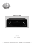
Power Amplifier
MC303
Owner’s Manual
McIntosh Laboratory, Inc.
2 Chambers Street Binghamton, New York
13903-2699 Phone: 607-723-3512
www.mcintoshlabs.com
The lightning flash with arrowhead,
within an equilateral triangle, is
intended to alert the user to the
presence of uninsulated “dangerous voltage” within the product’s
enclosure that may be of sufficient
magnitude to constitute a risk of
electric shock to persons.
WARNING - TO REDUCE RISK OF
FIRE OR ELECTRICAL SHOCK, DO
NOT EXPOSE THIS EQUIPMENT TO
RAIN OR MOISTURE.
IMPORTANT SAFETY
INSTRUCTIONS!
PLEASE READ THEM BEFORE
OPERATING THIS EQUIPMENT.
1. Read these instructions.
2. Keep these instructions.
3. Heed all warnings.
4. Follow all instructions.
5. Do not use this apparatus near water.
6. Clean only with a dry cloth.
7. Do not block any ventilation openings. Install in
accordance with the manufacturer’s instructions.
8. Do not install near any heat sources such as radiators, heat registers, stoves, or other apparatus
(including amplifiers) that produce heat.
9. Do not defeat the safety purpose of the polarized
or grounding-type plug. A polarized plug has two
blades with one wider than the other. A grounding type plug has two blades and a third grounding prong. The wide blade or the third prong are
provided for your safety. If the provided plug does
not fit into your outlet, consult an electrician for
replacement of the obsolete outlet.
10. Protect the power cord from being walked on or
pinched particularly at plugs, convenience receptacles, and the point where they exit from the
apparatus.
2
The exclamation point within an
equilateral triangle is intended to
alert the user to the presence of important operating and maintenance
(servicing) instructions in the literature accompanying the appliance.
NO USER-SERVICEABLE PARTS
INSIDE. REFER SERVICING TO
QUALIFIED PERSONNEL.
To prevent the risk of electric shock, do not remove cover or
back. No user-serviceable parts inside.
11. Only use attachments/accessories specified by the
manufacturer.
12. Use only with the cart, stand, tripod, bracket, or
table specified by the manufacturer,
or sold with the apparatus. When a
cart is used, use caution when moving the cart/apparatus combination
to avoid injury from tip-over.
13. Unplug this apparatus during lightning storms or
when unused for long periods of time.
14. Refer all servicing to qualified service personnel. Servicing is required when the apparatus has
been damaged in any way, such as power-supply
cord or plug is damaged, liquid has been spilled or
objects have fallen into the apparatus, the apparatus has been exposed to rain or moisture, does not
operate normally, or has been dropped.
15. Do not expose this equipment to dripping or
splashing and ensure that no objects filled with liquids, such as vases, are placed on the equipment.
16. To completely disconnect this equipment from the
a.c. mains, disconnect the power supply cord plug
from the a.c. receptacle.
17. The mains plug of the power supply cord shall
remain readily operable.
18. Do not expose batteries to excessive heat such as
sunshine, fire or the like.
Thank You
Table of Contents
Your decision to own this McIntosh MC303 Power Amplifier ranks you at the very top among discriminating music
listeners. You now have “The Best.” The McIntosh dedication to “Quality,” is assurance that you will receive many
years of musical enjoyment from this unit.
Please take a short time to read the information in this
manual. We want you to be as familiar as possible with all
the features and functions of your new McIntosh.
Safety Instructions.............................................................. 2
Thank You and Please Take a Moment............................... 3
Technical Assistance and Customer Service...................... 3
Table of Contents................................................................ 3
General Information........................................................3-4
Connector Information....................................................... 4
Introduction......................................................................... 4
Performance Features......................................................... 4
Dimensions......................................................................... 5
Installation.......................................................................... 6
Rear Panel Connections and Switch................................... 7
How to Connect............................................................... 8-9
Connection Diagrams (Separate Sheet) MC1A and MC1B
Front Panel Displays and Controls.....................................10
How to Operate..................................................................11
Technical Description...................................................12-15
Photos............................................................................16-17
Specifications.....................................................................18
Packing Instruction............................................................19
Please Take A Moment
The serial number, purchase date and McIntosh Dealer
name are important to you for possible insurance claim or
future service. The spaces below have been provided for
you to record that information:
Serial Number:___________________________________
Purchase Date:_ __________________________________
Dealer Name:_ ___________________________________
Technical Assistance
If at any time you have questions about your McIntosh
product, contact your McIntosh Dealer who is familiar
with your McIntosh equipment and any other brands that
may be part of your system. If you or your Dealer wish
additional help concerning a suspected problem, you can
receive technical assistance for all McIntosh products at:
McIntosh Laboratory, Inc.
2 Chambers Street
Binghamton, New York 13903
Phone: 607-723-1545
Fax: 607-724-0549
Customer Service
If it is determined that your McIntosh product is in need of
repair, you can return it to your Dealer. You can also return
it to the McIntosh Laboratory Service Department. For
assistance on factory repair return procedure, contact the
McIntosh Service Department at:
McIntosh Laboratory, Inc.
2 Chambers Street
Binghamton, New York 13903
Phone: 607-723-3515
Fax: 607-723-1917
General Information
Caution: The MC303 Amplifier weight is 150 pounds (70.3
kilograms). It requires two or more persons to safely
handle when moving the amplifier.
1. The following Connecting Cable is available from the McIntosh Parts Department:
Power Control Cable Part No. 170-202
Six foot, 2 conductor shielded, with two 1/8 inch stereo
mini phone plugs.
2. For additional connection information, refer to the owner’s
manual(s) for any component(s) connected to the MC303.
3. The MC303 mutes the speaker output for approximately two
seconds when first turned on.
4. In the event the MC303 overheats, due to improper ventilation
and/or high ambient temperature, the protection circuits will
activate. The Front Panel Power Guard LEDs will continuously indicate ON and the audio will be muted. When the
MC303 has returned to a safe operating temperature, normal
operation will resume.
5. For the best performance it is important to minimize an impedance mismatch. An impedance mismatch can occur when a
Loudspeaker of a given impedance rating is connected to the
MC303 Output Terminals with a different impedance rating.
For example, a Loudspeaker with an impedance rating of 2
Ohms is connected to the MC303 8 Ohm Output Terminals.
The impedance of a Loudspeaker actually varies as the
Loudspeaker reproduces different frequencies. As a result, the
nominal impedance rating of the Loudspeaker (usually measured at a midrange frequency) might not always agree with
the impedance of the Loudspeaker at low frequencies where
the greatest amount of power is required.
Copyright 2008 © by McIntosh Laboratory, Inc.
3
Connector Information, Introduction and Performance Features
General Information, con’t
6. When discarding the unit, comply with local rules
or regulations. Batteries should never be thrown
away or incinerated but disposed of in accordance
with the local regulations concerning battery disposal.
7. For additional information on the MC303 and other
McIntosh Products please vist the McIntosh Web
Site at www.mcintoshlabs.com.
8. When the MC303 is operated in the USA or Canada and the
main fuse, located on the rear panel, is in need of replacement use only the following part:
Bussman ABC-15-R or Littlefuse 314-015P
Connector and Cable Information
XLR Connectors
Below is the Pin configuration for the XLR Balanced Input
Connectors on the MC303. Refer to the diagram for connection:
PIN 1: Shield/Ground
PIN 2: + Output
PIN 3: - Output
PIN 2
PIN 1
PIN 3
Power Control Connector
The MC303’s Power Control Inputs receive On/Off signals
of +5 volts. An additional connection
Power
is for controlling the illumination of
Control
the MC303 Power Output Meters.
Meter
The 1/8 inch stereo mini phone plug
Illumination
Control
connects to a McIntosh A/V Control
Ground
Center Power Control Output.
Note: The Power Control Connecting Cable is available from
the McIntosh Parts Department:
Data and Power Control Cable Part No. 170-202
Six foot, shielded 2 conductor, with 1/8 inch stereo mini
phone plugs on each end.
Introduction
Now you can take advantage of traditional McIntosh
standards of excellence in the MC303 Power Amplifier.
The 300 watt high current output per channel will drive
any high quality loudspeaker system to its ultimate performance. The MC303 reproduction is sonically transparent and absolutely accurate. The McIntosh Sound is “The
Sound of the Music Itself.”
Performance Features
• Power Output
The MC303 is a Power Amplifier with a capability of 300
watts per channel (all channels driven) into 2, 4 or 8 ohm
speakers with less than 0.005% distortion. The Power Am4
plifier circuitry uses Thermal Trak1 Output Transistors for
lower distortion and cool operation.
• Balanced and Unbalanced Inputs
Balanced connections guard against induced noise and allow long cable runs without compromising sound quality.
• Power Guard
The patented McIntosh Power Guard circuit prevents the
amplifier from being over driven into clipping, with its
harsh distorted sound that can also damage your valuable
loudspeakers.
• Sentry Monitor and Thermal Protection
McIntosh Sentry Monitor power output stage protection
circuits ensure the MC303 will have a long and trouble free
operating life. Built-in Thermal Protection Circuits guard
against overheating.
• Patented Autoformer
McIntosh designed and manufactured Output Autoformers
provide an ideal match between the amplifier output stages
and speaker loads of 2, 4 and 8 ohms. The Autoformers
also provide perfect DC protection for your valuable loudspeakers.
• Special Power Supply
A regulated Power Supply, a very large Power Transformer
and Capacitors ensure stable noise free operation even
though the power line varies.
• Illuminated Power Meter
The Illuminated Power Output Watt Meter on the MC303
is peak responding, and indicates the power output of the
amplifier. The Front Panel Meter Illumination may be
switched Off at any time.
• Fiber Optic Solid State Front Panel Illumination
The even illumination of the Front Panel is accomplished
by the combination of custom designed Fiber Optic Light
Diffusers and extra long life Light Emitting Diodes
(LEDs).
• Glass Front Panel and Super Mirror Chassis Finish
The famous McIntosh Illuminated Glass Front Panel and
the Stainless Steel Chassis with Super Mirror Finish ensures the pristine beauty of the MC303 will be retained for
many years.
1
ThermalTrak™ and ON Semiconductor are trademarks of Semiconductor Components Industries, LLC
Dimensions
Dimensions
The following dimensions can assist in determining the
best location for your MC303. There is additional information on the next page pertaining to installing the MC303
into cabinets.
17-3/4"
45.09cm
10-7/8"
Front View of the MC303
27.62cm
12-3/8"
31.43cm
17-3/8"
44.15cm
Rear View of the MC303
F15AH 125V
12-1/4"
31.11cm
19-1/2"
49.50cm
18"
1-5/8"
45.72cm
4.12cm
Side View of the MC303
3/16"
0.48cm
1-1/2"
3.81cm
14"
35.60cm
10-1/2"
26.70cm
1-9/16"
3.96cm
5
Installation
Installation
sure to cut out a ventilation hole in the mounting shelf acThe MC303 can be placed upright on a table or shelf,
cording to the dimensions in the drawing.
standing on its four feet. It also can be custom installed in
a piece of furniture or cabinet of your choice. The four feet
1
When the MC303 is installed together with other McIntosh
may be removed from the bottom of the MC303 when it is
Components, check clearances on all components before
custom installed as outlined below. The four feet together
proceeding.
with the mounting screws should be retained for possible
future use if the MC303 is
removed from the custom
17-9/16"
installation and used free
44.62cm
standing. The required
panel cutout, ventilation
cutout and unit dimensions are shown.
Always provide adequate
10 -13/16"
MC303 Front Panel
ventilation for your
27.46cm
Custom
Cabinet
Cutout
MC303. Cool operation
ensures the longest possible operating life for any
electronic instrument. Do
not install the MC303 directly above a heat generating component such as a
6"
high powered amplifier. If
Cabinet
15.24cm
Cutout Opening for Custom Mounting
Front
all the components are inPanel
stalled in a single cabinet,
a quiet running ventilation fan can be a definite
Opening
for Ventilation
asset in maintaining all
the system components at
the coolest possible operating temperature.
A custom cabinet instalMC303 Side View
in Custom Cabinet
lation should provide the
following minimum spacChassis
Spacers
ing dimensions for cool
operation.
Cutout Opening for Ventilation
Allow at least 6 inches
(15.24cm) above the top,
Support
1"
2 inches (5.08cm) below
Shelf
2.54cm
the bottom and 1 inch
(2.54cm) on each side of
the Power Amplifier, so
that airflow is not ob14-1/2"
36.83cm
21/32"
structed. Allow 19-1/2
MC303 Bottom View
1.67cm
15-5/16"
14"
inches (49.53cm) depth
in Custom Cabinet
38.91cm
Cutout Opening
35.56cm
behind the front panel.
for Ventilation
Allow 1-5/8 inch (4.12cm)
in front of the mounting
Note: Center the cutout Horizontally on the unit.
panel1 for clearance. Be
For purposes of clarity, the above
illustration is not drawn to scale.
6
Rear Panel Connections and Switch
UNBALANCED INPUT 3
for an audio cable from an
A/V Control Center or Preamplifier audio output
POWER CONTROL IN
receives turn On/Off signal
from a McIntosh component
and the POWER CONTROL
OUT sends a turn On/Off
signal to the next McIntosh
Component
BALANCED INPUT 3
for an audio cable from
an A/V Control Center
or Preamplifier audio
output
BALANCED INPUT 2
for an audio cable from
an A/V Control Center
or Preamplifier audio
output
UNBALANCED INPUT 2
for an audio cable from an
A/V Control Center or Preamplifier audio output
BALANCED INPUT 1
for an audio cable from
an A/V Control Center
or Preamplifier audio
output
UNBALANCED INPUT 1
for an audio cable from an
A/V Control Center or Preamplifier audio output
F15AH 125V
OUTPUT 3 Connections
for 2 ohm, 4 ohm or 8 ohm
Loudspeaker
OUTPUT 2 Connections
for 2 ohm, 4 ohm or 8 ohm
Loudspeaker
Connect the MC303
power cord to a live AC
outlet. Refer to the rear
panel to determine the
correct voltage
OUTPUT 1 Connections
for 2 ohm, 4 ohm or 8 ohm
Loudspeaker
Main Fuse holder, refer to information on
the back panel of your MC303 to determine
the correct fuse size and rating. When used
in the USA and Canada refer to General
Information note number 8 on page 4.
7
How to Connect for Center and Surround
Channels
Caution: The supplied AC Power Cord should not be
connected to the Rear Panel of the MC303
Amplifier until after the Loudspeaker Connections have been made. Failure to observe this
could result in Electric Shock. For additional
instruction on making Loudspeaker Connections contact your McIntosh Dealer or McIntosh Technical Support.
The connection instructions below, together with the
MC303 Connection Diagram located on the separate folded
sheet “Mc1A, is an example of a typical audio/video system. Your system may vary from this, however the actual
components would be connected in a similar manner. For
additional information refer to “Connector and Cable Information” on page 4.
1. For Remote Power Control, connect a power control
cable from the A/V Control Center or Preamplifier
Power Control Out to the Right Front Channel Power
Amplifier Power Control In. Connect a second power
control cable from the Right Front Channel Power
Amplifier Power Power Control Out to the Left Front
Channel Power Amplifier Power Control In.
2. Connect a power control cable from the Left Front
Channel Power Amplifier Power Power Control Out to
the MC303 POWER CONTROL IN.
3. Connect cables from the Balanced Outputs of the A/V
Control Center or Preamplifier (Left and Right Front
Channels) to the Left and Right Front Power Amplifiers.
Note: An optional hookup is to use the UNBALanced INPUTS with unbalanced cables instead of balanced.
However, both type of connections for a given Input
should not be used at the same time.
4. Connect cables from the Balanced Outputs of the A/V
Control Center or Preamplifier (Center and Surround
Channels) to the MC303 BALANCED INPUTs (1-3).
When connecting Loudspeakers to the MC303 it is very
important to use cables of adequate size, so there is little to
no power loss in the cables. The size is specified in Gauge
Numbers or AWG (American Wire Gauge). The smaller
the Gauge number, the larger the wire size:
Loudspeaker Cable Distance vs Wire Gauge Guide
Loudspeaker
Impedance
25 feet
(7.62 meters)
or less
50 feet
(15.24 meters)
or less
100 feet
(30.48 meters)
or less
2 Ohms
12AWG
10AWG
8AWG
4 Ohms
14AWG
12AWG
10AWG
8 Ohms
16AWG
14AWG
12AWG
5. This McIntosh MC303 Power Amplifier is designed for
8
the connection of a single Loudspeaker per amplifier
channel, with an impedance of 2 ohms, 4 ohms or 8
ohms.
Note: The remaining Amplifier Loudspeaker Terminals
should not be connected to another Loudspeaker.
6. Prepare the Loudspeaker Hookup Cables that attach to
the Amplifier by choosing one of the methods below:
Bare wire cable ends:
Carefully remove sufficient insulation from the cable
ends, refer to figures 1, 2 & 3. If the cable is stranded, carefully twist
the strands together
as tightly as possible.
Figure 2
Figure 3
Figure 1
Note: If desired, the
twisted ends can
be tinned with solder to keep the strands together,
or attach spade lug and/or banana connector.
Spade lug or prepared wire connection:
Insert the spade lug connector or prepared section of
the cable end into the terminal side access hole, and
tighten the terminal
cap until the cable is
firmly clamped into
Figure 4
Figure 5
Figure 6
the terminal so the
wires cannot slip out. Refer to figures 4, 5 & 6.
Banana plug connection:
Insert the banana plug into the hole at the top of the
terminal. Refer to figures A and B.
Note: Banana
Plugs are
for use in
the United
States and
Canada
only.
7. Connect the Loudspeaker hookup cables from a single
Loudspeaker to the output terminals that match the
impedance of OUPUT 1, being careful to observe the
correct polarities. Output impedance connections of 2
ohms, 4 ohms and 8 ohms are provided. If the Loudspeaker’s impedance is in-between the available connections, use the nearest lower impedance connection.
Refer to “General Information” Note 5 on page 3 for
additional information.
WARNING: Loudspeaker terminals are hazardous live
and present a risk of electric shock.
8. In a similar manner, connect a Loudspeaker to OUTPUT 2 and connect the remaining Loudspeaker to
OUTPUT 3.
9. Connect the MC303 Power Cord to a live AC outlet.
How to Connect
How to Connect for Left, Center and Right
Channels
Caution: The supplied AC Power Cord should not be
connected to the Rear Panel of the MC303
Amplifier until after the Loudspeaker Connections have been made. Failure to observe this
could result in Electric Shock. For additional
instruction on making Loudspeaker Connections contact your McIntosh Dealer or McIntosh Technical Support.
The connection instructions below, together with the
MC303 Connection Diagram located on the separate folded
sheet “Mc1B, is an example of a typical audio/video system. Your system may vary from this, however the actual
components would be connected in a similar manner. For
additional information refer to “Connector and Cable Information” on page 4.
1. For Remote Power Control, connect a power control cable from the A/V Control Center or Preamplifier Power
Control Out to the MC303 POWER CONTROL IN.
2. Connect a second power control cable from the MC303
POWER CONTROL OUT to the Left and Right Surround Channel Power Amplifier Power Control In.
3. Connect cables from the Balanced Outputs of the A/V
Control Center or Preamplifier (Left, Center and Right
Front Channels) to the MC303 BALANCED INPUTs
(1-3).
Note: An optional hookup is to use the UNBALanced INPUTS with unbalanced cables instead of balanced.
However, both type of connections for a given Input
should not be used at the same time.
4. Connect cables from the Balanced Outputs of the A/V
Control Center or Preamplifier (Surround Channels) to
the Left and Right Surround Channel Power Amplifier.
When connecting Loudspeakers to the MC303 it is very
important to use cables of adequate size, so there is little to
no power loss in the cables. The size is specified in Gauge
Numbers or AWG (American Wire Gauge). The smaller
the Gauge number, the larger the wire size:
Loudspeaker Cable Distance vs Wire Gauge Guide
Loudspeaker
Impedance
25 feet
(7.62 meters)
or less
50 feet
(15.24 meters)
or less
100 feet
(30.48 meters)
or less
2 Ohms
12AWG
10AWG
8AWG
4 Ohms
14AWG
12AWG
10AWG
8 Ohms
16AWG
14AWG
12AWG
5. This McIntosh MC303 Power Amplifier is designed for
the connection of a single Loudspeaker per amplifier
channel, with an impedance of 2 ohms, 4 ohms or 8
ohms.
Note: The remaining Amplifier Loudspeaker Terminals
should not be connected to another Loudspeaker.
6. Prepare the Loudspeaker Hookup Cables that attach to
the Amplifier by choosing one of the methods below:
Bare wire cable ends:
Carefully remove sufficient insulation from the cable
ends, refer to figures 1, 2 & 3. If the cable is stranded, carefully twist the strands together as tightly as
possible.
Note: If desired, the
twisted ends can
be tinned with
Figure 2
Figure 3
Figure 1
solder to keep
the strands together, or attach spade lug and/or
banana connector.
Spade lug or prepared wire connection:
Insert the spade lug connector or prepared section
of the cable end into the terminal side access hole,
and tighten the terminal cap until the cable is firmly
clamped into the
terminal so the wires
cannot slip out. Refer
Figure 4
Figure 5
Figure 6
to figures 4, 5 & 6.
Banana plug connection:
Insert the banana plug into the hole at the top of the
terminal. Refer to figures A and B.
Note: Banana
Plugs are
for use in
the United
States and
Canada
only.
7. Connect the Loudspeaker hookup cables from a single
Loudspeaker to the output terminals that match the
impedance of OUPUT 1, being careful to observe the
correct polarities. Output impedance connections of 2
ohms, 4 ohms and 8 ohms are provided. If the Loudspeaker’s impedance is in-between the available connections, use the nearest lower impedance connection.
Refer to “General Information” Note 5 on page 3 for
additional information.
WARNING: Loudspeaker terminals are hazardous live
and present a risk of electric shock.
8. In a similar manner, connect a Loudspeaker to OUTPUT 2 and connect the remaining Loudspeaker to
OUTPUT 3.
9. Connect the MC303 Power Cord to a live AC outlet.
9
Front Panel Displays and Switches
Meters indicate the Amplifier
Power Output of Channels 1-3
LEDs indicate when Amplifier Channels
1-3 POWER GUARD circuits activate
Standby Power On
Indicator
METER Switch selects
Meter Illumination Auto
(On) or Off
10
POWER Switch Turns
AC Power On/Off, or
On/Remote
How to Operate
How to Operate
Power On
To have the MC303 automatically turn On or Off when an
A/V Control Center or Preamplifier turns on or off, rotate
the power switch to the REMOTE
position. For manual operation,
rotate the power switch to the ON
or OFF position as desired. Refer
to figure 8.
Note: There must be a power control connection between the
MC303 and the A/V Control
Center or Preamplifier, in
order for the remote power
turn-on to function.
Power Guard
During normal operation, the Front Panel Power Guard
Indicators will momentarily illuminate during peaks in the
audio signals. Refer to figure 11. In
the event the MC303 overheats, due
to improper ventilation and/or high
ambient temperature, the internal
Figure 11
protection circuits will activate. The
Front Panel Power Guard Indicators
will continuously illuminate and the audio will be muted.
When the MC303 has returned to a safe operating temperature, normal operation will resume.
Figure 8
Meters
Rotate the METER LIGHTS Switch to select the Meter Illumination Mode you desire. Refer to figure 9.
OFF - Meter Illumination
is switched OFF and
the meters will continue to indicate the
power output.
AUTO - Meter Illumination
is switched ON.
When Power Control
Input of the MC303
is connected to an
A/V Control Center
Figure 9
or Preamplifier with
Remote Meter Illumination Control, the Meter
Illumination will automatically be remotely
controlled (On/Off).
The MC303 Meters respond to all the musical information being produced by the three Power Amplifier Circuits.
Refer to figure 10. They indicate to an accuracy of at least
95% of the power output with only a single cycle of a
2000Hz tone burst.
Figure 10
11
Technical Description
McIntosh Laboratory, the company who introduced the
world’s first amplifier that could be called “High Fidelity”,
has done it again. The McIntosh engineering staff has created a power amplifier without compromise, using the most
advanced McIntosh circuit design concepts.
A continuous average power output rating of 300 watts
per channel and with an output current of greater than 60
amperes per channel, making this one of the most advanced and powerful amplifiers McIntosh has ever manufactured. The distortion limits for the MC303 are no more
than 0.005% at rated power output for all frequencies from
20Hz to 20,000Hz. Typical performance at mid frequencies
is less than 0.0002%. The true distortion readings on the
MC303 are so low, it takes special measuring techniques
to make accurate readings. The MC303 can deliver the
best possible performance from any type of high quality
loudspeaker system.
Creating an amplifier with this level of performance did
not come easily. Many months of design, testing and measuring were required. Extensive controlled listening tests,
the ultimate form of measuring, were made before the final
design was accepted.
Inside Bottom View of the MC303
12
Technical Description
POSITIVE
SENTRY
MONITOR
Power Amplifier
Block Diagram
THERMAL
TRAK
DC BIAS
com
(one channel shown)
NEGATIVE
SENTRY
MONITOR
BALANCED
AMP
Figure 12
Design Philosophy
The design philosophy incorporated in the MC303 involved several different techniques, all based on sound
scientific logic. Refer to figure 12. Every stage of voltage
or current amplification must be as linear as possible prior
to the use of negative feedback. McIntosh engineers know
how to properly design negative feedback circuits so they
contribute to the extremely low distortion performance
expected from a McIntosh amplifier. The typical McIntosh
owner would never accept the approximately 100 times
higher distortion of many non-feedback designs.
All transistors are selected to have nearly constant current gain over the entire current range they must cover. The
12 Power Transistors used in each channel of the MC303
Power Output
Circuitry, have
matched uniform
current gain, high
current bandwidth product and
a large active region safe operating area. Refer to
figure 13. These
Power Transistors
are the very latest
in semiconductor technology
Figure 13
and incorporate
a new design known as ThermalTrak™. Refer
to figure 14. This allows for the instantaneous
and accurate monitoring of the Power Transistor Temperature. The MC303 Power Output
Circuitry has a specially designed bias circuit
to take full advantage of the ThermalTrak™
Power Transistors and thus precisely controls
the power amplifier operation over a wide
Figure 14
range of music conditions with the benefits of lower distortion and cooler operation.
The MC303 can provide greater than 60 amperes peak
output current to drive uneven speaker loads. Some poor
speaker designs have input impedance that dip to 1 or 2
ohms at various frequencies and the MC303 has the output
current reserve to drive them.
The high efficiency circuit design of the MC303 contributes to low operating temperatures. More than 2,100
square inches of heat sink area keep the MC303 operating
safely with convection cooling. No fans are needed. Precision metal film resistors and low dielectric absorption film
capacitors are used in all critical circuit locations.
Autoformers
The output signal of the MC303 Power Amplifier Circuitry
is coupled to the Loudspeaker via the unique McIntosh
Output Autoformer. Refer to figure 15. The unequaled expertise of McIntosh in the design
and manufacturing of autoformers is legendary
in the high fidelity industry.
All solid state
power amplifier
output circuits
work best into
Figure 15
what is called
an optimum load. This optimum load may vary considerably from what a loudspeaker requires. In the case of more
than one Loudspeaker connected in parallel, the load to
the power amplifier may drop to two ohms or even less. A
power amplifier connected to a load that is lower than optimum, causes more output current to flow, which results in
extra heat being generated in the power output stage. This
13
increase in temperature will result in a reduced life
expectancy for the amplifier.
The Autoformer creates an ideal match between the
Power Amplifier Output Circuitry and the Loudspeaker.
There is absolutely no performance limitation with an
Autoformer. Its frequency response from below 20Hz to
well beyond 20,000Hz exceeds the Power Output Circuitry
Frequency Response, and extends well beyond the audible
range. Its distortion level is so low it is virtually impossible
to measure. In the rare event of a power amplifier output
circuit failure, the McIntosh Autoformer provides absolute
protection from possible damage to your valuable Loudspeakers.
Protection Circuits
The different types of protection circuits incorporated in
the MC303 insure a long and safe operating life.
The MC303 incorporates the McIntosh Sentry Monitor
output transistor protection circuit. Refer to figure 16.
There is absolutely no
compromise in sonic
performance with this
circuit, and it ensures
safe operation of the
amplifier under even
the most extreme opNormal
erating conditions.
Operating
Area
The MC303 also
includes the unique
patented McIntosh
Sentry Monitor
Safety Area
Power Guard Circuit.
Power Guard elimiOutput Transistor Failure
nates the possibility
of ever overdriving
Figure 16
the amplifier into
clipping. Refer to figures 17, 18 and 19. An overdriven
amplifier can produce both audible and inaudible distortion
levels exceeding 40%. The audible distortion is unpleasant to hear, but the inaudible ultrasonic distortion is also
undesirable, since it can
Input Test Signal
damage valuable loudspeaker
system tweeters. You will
never experience the harsh
and damaging distortion due
to clipping.
The Power Guard circuit is a
waveform comparator, monitoring both the input and output waveforms. Under normal
operating conditions, there
are no differences between
Figure 17
14
the shape of these waveforms.
If an amplifier channel is
overdriven, there will be a difference between the two signal
waveforms. When the difference exceeds 0.3% the Power
Guard activates the PG light
and a dynamic electronic attenuator at the amplifier input
reduces the input volume just
enough to prevent any further
increase in distortion. The
Power Guard circuit acts so
fast that there are absolutely
no audible side effects and
the sonic purity of the music
reproduction is perfectly
preserved. The MC303 Power
Amplifier with Power Guard
is not limited to just the rated
power output, but will actually produce distortion free
output well above its rated
power due to the McIntosh
philosophy of conservative
design.
Without Power Guard
Figure 18
With Power Guard
Figure 19
Power Supply Circuits
To compliment the design of the MC303 Power Amplifier
Circuitry, there is a high current high voltage power supply
for the three channels. Refer to figure 20 on page 15. The
power amplifiers draw high current from the AC power
line. Therefore, it is important that they plug directly into
the wall outlet.
The MC303 incorporates a very large high current
Main Power Transformer. Refer to figure 21. It is enclosed
in the legendary McIntosh Potted Enclosures and weighs
38 lbs. The super size multiple large main filter capacitors
Figure 21
Technical Description, con’t
Power Supply
Block Diagram
STANDBY
TRANSFORMER
STANDBY
SUPPLY
Figure 20
can store over 200 Joules of energy, for the three amplifier
channels, necessary for the wide dynamic range “Digital
Audio” demands. Refer to figure 22.
Figure 22
There is also a fully regulated low voltage power supply to
guarantee excellent signal to noise ratio. Refer to figure 22.
Also, most owners desire one power switch for the
whole audio system. The MC303 is equipped with a circuit
that provides remote Power Control from a McIntosh A/V
Control Center. When the A/V Control Center is switched
On, a (+5V) signal operates the power relay in the MC303.
The MC303 also has a remote Power Control Out Jack. The
Power Control signal from this jack is delayed by a fraction of a second so that the turn on power surge of the next
power amplifier occurs at a later time. This helps prevent
power circuit overload that could trip circuit breakers or
blow fuses, a very important feature in a high power Home
Theater System employing multiple Power Amplifiers.
15
Top View of the MC303
16
Photos
Angle View of the MC303
Rear View of the MC303
17
Specifications
Specifications
Power Output
Minimum sine wave continuous average power output per
channel, all channels operating:
300 watts into a 2 ohm, 4 ohm or 8 ohm load
Output Load Impedance
2, 4 or 8 ohms
Rated Power Band
20Hz to 20,000Hz
Total Harmonic Distortion
0.005% maximum harmonic distortion at any power level
from 250 milliwatts to rated power, 20Hz to 20,000Hz
Dynamic Headroom
1.8dB
Frequency Response
+0, -0.25dB from 20Hz to 20,000Hz
+0, -3dB from 10Hz to 100,000Hz
Input Sensitivity (for rated output)
1.7 Volt Unbalanced
3.4 Volt Balanced
Signal To Noise Ratio (A-Weighted)
112dB below rated output
Intermodulation Distortion
0.005% maximum, if the instantaneous peak power output
does not exceed twice the rated power output for any combination of frequencies from 20Hz to 20,000Hz.
Wide Band Damping Factor
Greater than 40
Input Impedance
10,000 ohms
Power Guard
Less than 2% THD with up to 14dB overdrive at 1,000Hz
Power Control Input
5VDC - 12VDC
Power Control Output
12VDC, 25mA maximum, delay 0.2 seconds
18
Power Requirements
100 Volts, 50/60Hz at 12 Amps
110 Volts, 50/60Hz at 11 Amps
120 Volts, 50/60Hz at 10 Amps
220 Volts, 50/60Hz at 6 Amps
230 Volts, 50/60Hz at 6 Amps
240 Volts, 50/60Hz at 6 Amps
Standby: Less than 1 watt
Note: Refer to the rear panel of the MC303 for the correct
voltage.
Overall Dimensions
Width is 17-3/4 inches (45.09cm)
Height is 12-3/8 inches (31.43cm) including feet
Depth is 22 inches (55.88cm) including the Front Panel and
Cables
Weight
155 pounds (70.3 kg) net, 180 pounds (81.6 kg) in shipping
carton
Shipping Carton Dimensions
Width is 31 inches (78.74cm)
Depth is 28 inches (71.12cm)
Height is 17-1/4 inches (43.82cm)
Packing Instructions
Packing Instructions
In the event it is necessary to repack the equipment for
shipment, the equipment must be packed exactly as shown
below. It is very important that the four feet are attached to
the bottom of the equipment. This will ensure the proper
equipment location on the bottom foam pad. Failure to do
this will result in shipping damage.
Use the original shipping carton and interior parts only
if they are all in good serviceable condition. If a shipping
carton or any of the interior part(s) are needed, please call
or write Customer Service Department of McIntosh Laboratory. Please see the Part List for the correct part numbers.
Quantity
1
1
2
3
Part Number
034105
034104
034439
034441
4
018445
Description
Shipping carton top
Shipping carton bottom
Foam Pad (top and bottom)
Foam Ring
Feet
19
McIntosh Laboratory, Inc.
2 Chambers Street
Binghamton, NY 13903
www.mcintoshlabs.com
The continuous improvement of its products is the
policy of McIntosh Laboratory Incorporated who
reserve the right to improve design without notice.
Printed in the U.S.A.
McIntosh Part No. 04109800