1
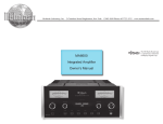
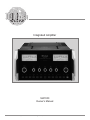
Integrated Amplifier MA7000 Owner’s Manual McIntosh Laboratory, Inc. 2 Chambers Street Binghamton, New York 13903-2699 Phone: 607-723-3512 FAX: 607-724-0549 The lightning flash with arrowhead, within an equilateral triangle, is intended to alert the user to the presence of uninsulated “dangerous voltage” within the product’s enclosure that may be of sufficient magnitude to constitute a risk of electric shock to persons. WARNING - TO REDUCE RISK OF FIRE OR ELECTRICAL SHOCK, DO NOT EXPOSE THIS EQUIPMENT TO RAIN OR MOISTURE. IMPORTANT SAFETY INSTRUCTIONS! PLEASE READ THEM BEFORE OPERATING THIS EQUIPMENT. 1. Read these instructions. 2. Keep these instructions. 3. Heed all warnings. 4. Follow all instructions. 5. Do not use this apparatus near water. 6. Clean only with a dry cloth. 7. Do not block any ventilation openings. Install in accordance with the manufacturer’s instructions. 8. Do not install near any heat sources such as radiators, heat registers, stoves, or other apparatus (including amplifiers) that produce heat. 9. Do not defeat the safety purpose of the polarized or grounding-type plug. A polarized plug has two blades with one wider than the other. A grounding type plug has two blades and a third grounding prong. The wide blade or the third prong are provided for your safety. If the provided plug does not fit into your outlet, consult an electrician for replacement of the obsolete outlet. 10. Protect the power cord from being walked on or pinched particularly at plugs, convenience receptacles, and the point where they exit from the apparatus. 2 The exclamation point within an equilateral triangle is intended to alert the user to the presence of important operating and maintenance (servicing) instructions in the literature accompanying the appliance. NO USER-SERVICEABLE PARTS INSIDE. REFER SERVICING TO QUALIFIED PERSONNEL. To prevent the risk of electric shock, do not remove cover or back. No user-serviceable parts inside. 11. Only use attachments/accessories specified by the manufacturer. 12. Use only with the cart, stand, tripod, bracket, or table specified by the manufacturer, or sold with the apparatus. When a cart is used, use caution when moving the cart/apparatus combination to avoid injury from tip-over. 13. Unplug this apparatus during lightning storms or when unused for long periods of time. 14. Refer all servicing to qualified service personnel. Servicing is required when the apparatus has been damaged in any way, such as power-supply cord or plug is damaged, liquid has been spilled or objects have fallen into the apparatus, the apparatus has been exposed to rain or moisture, does not operate normally, or has been dropped. 15. Do not expose this equipment to dripping or splashing and ensure that no objects filled with liquids, such as vases, are placed on the equipment. 16. To completely disconnect this equipment from the a.c. mains, disconnect the power supply cord plug from the a.c. receptacle. 17. The mains plug of the power supply cord shall remain readily operable. 18. Do not expose batteries to excessive heat such as sunshine, fire or the like. Thank You Table of Contents Your decision to own this McIntosh MA7000 Integrated Amplifier ranks you at the very top among discriminating music listeners. You now have “The Best.” The McIntosh dedication to “Quality,” is assurance that you will receive many years of musical enjoyment from this unit. Please take a short time to read the information in this manual. We want you to be as familiar as possible with all the features and functions of your new McIntosh. Safety Instructions ............................................................ 2 Thank You and Please Take a Moment............................. 3 Technical Assistance and Customer Service .................... 3 Table of Contents .............................................................. 3 General Information ......................................................... 3 Connector and Cable Information .................................... 4 Introduction....................................................................... 4 Performance Features ....................................................... 4 Dimensions ....................................................................... 5 Installation ........................................................................ 6 Please Take A Moment The serial number, purchase date and McIntosh Dealer name are important to you for possible insurance claim or future service. The spaces below have been provided for you to record that information: Serial Number: __________________________________ Connections: Rear Panel Connections .................................................... 7 Connecting Components................................................... 8 Connection Diagrams (Separate Sheet) ..............Mc1A/1B Connecting Loudspeakers ................................................ 9 Dealer Name: ___________________________________ Remote Control: Remote Control Push-buttons ......................................... 10 How to Operate by Remote Control ............................... 11 Technical Assistance Front Panel Features: Front Panel Displays, Controls, Push-buttons and Jack . 12 Purchase Date: __________________________________ If at any time you have questions about your McIntosh product, contact your McIntosh Dealer who is familiar with your McIntosh equipment and any other brands that may be part of your system. If you or your Dealer wish additional help concerning a suspected problem, you can receive technical assistance for all McIntosh products at: McIntosh Laboratory, Inc. 2 Chambers Street Binghamton, New York 13903 Phone: 607-723-1545 Fax: 607-724-0549 Customer Service If it is determined that your McIntosh product is in need of repair, you can return it to your Dealer. You can also return it to the McIntosh Laboratory Service Department. For assistance on factory repair return procedure, contact the McIntosh Service Department at: McIntosh Laboratory, Inc. 2 Chambers Street Binghamton, New York 13903 Phone: 607-723-3515 Fax: 607-723-1917 Operation: How to Operate the MA7000..................................... 13-14 Additional Information: Technical Description ................................................ 15-17 Specifications .................................................................. 18 Packing Instruction .........................................................19 General Information 1. For additional connection information, refer to the owner’s manual(s) for any component(s) connected to the MA7000 Integrated Amplifier. 2. The Main AC Power going to the MA7000 and any other McIntosh Component(s) should not be applied until all the system components are connected together. Failure to do so could result in malfunctioning of some or all of the system’s normal operations. When the MA7000 and other McIntosh Components are in their Standby Power Off Mode, the Microprocessor’s Circuitry inside each component is active and communication is occurring between them. Copyright 2007 © by McIntosh Laboratory, Inc. 3 Connector Information, Introduction and Performance Features Connector and Cable Information Performance Features XLR Connectors Below is the Pin configuration for the XLR Balanced Input and Output Connectors on the MA7000. Refer to the diagram for connection: PIN 1: Shield/Ground PIN 2: + Output PIN 3: - Output • Power Output with Patented Autoformer The MA7000 consists of a 250 watts per channel stereo Power Amplifier with less than 0.005% distortion. The McIntosh designed and manufactured Autoformer allows connection of 2, 4 or 8 ohm Loudspeakers. PIN 2 PIN 1 PIN 3 PIN 2 PIN 3 PIN 1 Power Control Connector The MA7000 Power Control Output Jack sends Power On/ Off Signals when connected to other Power McIntosh Components. A 1/8 inch Control stereo mini phone plug is used for conN/C nection to the Power Control Output Ground on the MA7000. Note: The Data and Power Control Connecting Cable is available from the McIntosh Parts Department: Data and Power Control Cable Part No. 170-202 Six foot, shielded 2 conductor, with 1/8 inch stereo mini phone plugs on each end. Data Port Connectors The MA7000 Data Out Ports send Remote Control Signals to McIntosh Source Components. A 1/8 inch stereo mini phone plug is used for Data Signal connection. N/C Data Ground McIntosh Plug-In Jumper Connector The MA7000 utilizes a phono style Plug-In Jumper to connect the OUTPUT 1 (Preamplifier Output) Jack to the PWR AMP (Power Amplifier Input) Jack for each channel. Note: The Jumper Connector is available from the McIntosh Parts Department: McIntosh Jumper Connector Part No. 117-781 Introduction Now you can take advantage of traditional McIntosh standards of excellence in the MA7000 Integrated Amplifier. The Power Amplifier section of the MA7000, with a power output of 250 watts per channel, will drive a pair of quality Loudspeakers to a high level of performance. The flexible Preamplifier section provides connections for various input sources and may also be used to drive an external Power Amplifier. The MA7000 reproduction is sonically transparent and absolutely accurate. The McIntosh Sound is “The Sound of the Music Itself.” 4 • Electronic Switching and Balanced Connections The Preamplifier uses Logic Circuits controlling Electromagnetic Switches on all inputs and operating functions for reliable, noiseless, distortion free switching. There are two Balanced Inputs for connection of source components and a Balanced Preamplifier Output for driving an external Power Amplifier. • Power Guard The patented McIntosh Power Guard circuit prevents the amplifier from being overdriven into clipping with its harsh distorted sound that can also damage your valuable loudspeakers. • Sentry Monitor and Thermal Protection McIntosh Sentry Monitor power output stage protection circuits ensure the MA7000 will have a long and trouble free operating life. Built-in thermal protection circuits guard against overheating. • Illuminated Power Meters The Illuminated Power Output Watt Meters on the MA7000 are peak responding, and indicate the power output of the amplifier. • Power Control and Remote Control The Power Control Output connection provides convenient Turn-On/Off of McIntosh Source Components. The Data Ports together with the supplied Remote Control provides control of McIntosh Source Components connected to the MA7000. • Special Power Supply The large Power Transformer, multiple filter capacitors and regulated Power Supply ensures stable noise free operation even though the power line varies. • Fiber Optic Solid State Front Panel Illumination The even Illumination of the Front Panel is accomplished by the combination of custom designed Fiber Optic Light Diffusers and extra long life Light Emitting Diodes (LEDs). The glass Front Panel ensures the pristine beauty of the MA7000 will be retained for many years. Dimensions Dimensions The following dimensions can assist in determining the best location for your MA7000. There is additional information on the next page pertaining to installing the MA7000 into cabinets. 17-1/2" �� �� � Front View of the MA7000 � 44.45cm 8-13/16" 22.38cm 9-7/16" 23.97cm 16-13/16" 42.70cm Rear View of the MA7000 11-1/2" 29.21cm 19-3/4" 50.17cm 2-1/4" 16-7/16" 5.72cm 41.75cm Side View of the MA7000 8-1/4" 3/16" 0.48cm 7/8" 2.22cm 12-3/4" 32.39cm 20.96cm 1-1/4" 3.18cm 5 Installation Installation 6 � �� �� � Allow at least 6 inches (15.24cm) above the top, 2 inches The MA7000 can be placed upright on a table or shelf, (5.08cm) below the bottom and 1 inch (2.54cm) on each standing on its four feet. It also can be custom installed in side of the Integrated Amplifier, so that airflow is not oba piece of furniture or cabinet of your choice. The four feet structed. Allow 20 inches (50.8cm) depth behind the front may be removed from the bottom of the MA7000 when it panel. Allow 2-1/4 inch (5.72cm) in front of the mounting is custom installed as outlined below. The four feet togethpanel for handle clearance. Be sure to cut out a ventilation er with the mounting screws should be retained for possible future use if the MA7000 is removed from the custom hole in the mounting shelf according to the dimensions in the drawing. installation and used free standing. The required panel cutout, ventila17-1/16" tion cutout and 43.34cm unit dimensions are shown. Always provide adequate ventilation for your MA7000. 8-5/16" MA7000 Front Panel Cool opera21.11cm Custom Cabinet Cutout tion ensures the longest possible operating life for any electronic instrument. Do not install the 6" 15.24cm MA7000 directly Cutout Opening Cabinet above a heat for Front generating comCustom Mounting Panel ponent such as Opening a high powered for Ventilation amplifier. If all the components are installed in a single cabinet, MA7000 Side View a quiet runin Custom Cabinet ning ventilation fan can be a definite asset Cutout Opening for Ventilation in maintaining Chassis Support 45/8 " Spacers Shelf all the system 11.75cm components at the coolest pos9-1/2" sible operating 24.13cm temperature. A custom cabiMA7000 Bottom View 16" 11-1/2" Cutout net installation 40.64cm in Custom Cabinet 29.21cm Opening should provide for the following Ventilation minimum spacing dimensions Note: Center the cutout Horizontally on the unit. For purposes of clarity, the above for cool opera10" illustration is not drawn to scale. tion. 25.4cm Rear Panel Connections Connect the MA7000 power cord to a live AC outlet. Refer to information on the back panel of your MA7000 to determine the correct voltage for your unit EXT SENSOR connector permits the connection of a McIntosh IR Sensor for remote operation POWER CONTROL MAIN Output sends a turn-on signal to a McIntosh Component when the MA7000 is turned On Main Fuse holder, refer to information on the back panel of your MA7000 to determine the correct fuse size and rating RIGHT OUTPUT connections for a 2, 4 or 8 ohm loudspeaker POWER CONTROL 1 and 2 Output sends a turn-on signal to a McIntosh Component when the Outputs 1 and 2 Push-buttons are used POWER CONTROL ACC Output sends a turn-On, turn-Off signal to a McIntosh Component when using the MA7000 Remote Control ACC On/Off Push-buttons JUMPER PLUGS connect the Preamplifier OUTPUT 1 Jacks to the PWR AMP IN Jacks and are needed for normal operation GND terminal accepts a ground wire from a turntable CD1 and DVD Balanced and Unbalanced INPUTS accept high level program source signals PHONO accepts signals from a Moving Magnet phono cartridge DATA PORTS send signals to McIntosh Source Components to allow control with the MA7000 Remote Control PWR AMP input accepts signals from the internal Preamplifier or a separate external Preamplifier CD2, SERVER, REC and TUNER INPUTS accept high level program source signals OUTPUT 2 sends balanced signals to a separate external Power Amplifier with balanced inputs LEFT OUTPUT connections for a 2, 4 or 8 ohm loudspeaker RECord OUTPUT sends signals to the input of a recording device OUTPUT 1 sends signals to the internal Power Amplifier or a separate external Power Amplifier 7 Connecting Components The MA7000 has the ability to automatically switch power On/Off to McIntosh Source Components via the Power Control connections. The Data Port Connections allow for the remote operation of basic functions using the MA7000 Remote Control. With an external sensor connected to the MA7000, remote control operation of the system is possible from another room and/or when the MA7000 is located in a cabinet with the doors closed. The connection instructions below, together with the MA7000 Input and Output Connection Diagrams located on the separate folded sheet “Mc1A/1B”, are an example of a typical audio system. Your system may vary from this, however the actual components would be connected in a similar manner. For additional information refer to “Connector and Cable Information” on page 4. Power Control Connections: 1. Connect a Control Cable from the MA7000 POWER CONTROL MAIN Jack to the Power Control In on the McIntosh SACD/CD Player. 2. Connect a Control Cable from the McIntosh SACD/CD Player Power Control Out Jack to the McIntosh Audio/ Video Player Power Control In Jack. 3. Connect a Control Cable from the McIntosh Audio/ Video Player Power Control Out Jack to the McIntosh Tuner Power Control In Jack. 4. Connect a Control Cable from the McIntosh Tuner Power Control Out Jack to the McIntosh Music Server Power Control In Jack. 5. Optionally connect a Control Cable from the MA7000 POWER CONTROL OUTPUT 2 Jack to the McIntosh Power Amplifier (Secondary Room) Power Control In Jack. 6. Connect any additional McIntosh Components in a similar manner, as outlined in steps 1 thru 4. Data Control Connections: 7. Connect a Control Cable from the MA7000 TUNER DATA PORTS Jack to the McIntosh TUNER1 Data In Jack. 8. Connect a Control Cable from the MA7000 CD DATA PORT Jack to the McIntosh SACD/CD Player Data In Jack. 9. Connect a Control Cable from the MA7000 SERVER DATA PORT Jack to the McIntosh Music Server Data In Jack. 10. Connect a Control Cable from the MA7000 DVD DATA PORT Jack to the McIntosh Audio/Video Player Data In Jack. 11. Connect any additional McIntosh Components in a similar manner, as outlined in steps 7 thru 10. 8 Sensor Connections: 12. Connect a RG59U or RG6U Cable from the MA7000 EXT SENSOR “F” Connector to the McIntosh Sensor “F” Connector. Audio Connections: 13. Connect an Audio Cable from the MA7000 TUNER INPUT Jacks to the McIntosh TUNER 1 Fixed Output Jacks. 14. Connect Balanced Cables from the MA7000 CD INPUT Jacks to the McIntosh SACD/CD Player Fixed Balanced Output Jacks. Note: Unbalanced Audio Cables may be used instead of the Balanced Cables, but not both. 15. Connect an Audio Cable from the MA7000 SERVER INPUT Jacks to the McIntosh Music Server Output Jacks. 16. Connect an Audio Cable from the MA7000 REC OUTPUT Jacks to the McIntosh Music Server Input 1 Jacks. 17. Connect Balanced Cables from the MA7000 DVD INPUT Jacks to the McIntosh Audio/Video Player Balanced Output Jacks. Note: Unbalanced Audio Cables may be used instead of the Balanced Cables, but not both. 18. Connect the Audio Cables coming from the Turntable to the MA7000 PHONO INPUT Jacks. 19. Optionally, connect Balanced Cables from the MA7000 OUTPUT 2 Jacks to the McIntosh Power Amplifier (Secondary) Input Jacks. 20. Connect any additional McIntosh Components in a similar manner, as outlined in steps 14 thru 18. Ground Connections: 21. Connect the Ground Cable coming from the Turntable to the MA7000 GND Binding Post. AC Power Cords Connections: 22. Connect the MA7000 and any remaining components’ AC Power Cords to a live AC outlet as illustrated. How to Connect Connecting Loudspeakers Caution: The supplied AC Power Cord should not be connected to the Rear Panel of the MA7000 Amplifier until after the Loudspeaker Connections have been made. Failure to observe this could result in Electric Shock. For additional instruction on making Loudspeaker Connections contact your McIntosh Dealer or McIntosh Technical Support. When connecting Loudspeakers to the MA7000 it is very important to use cables of adequate size, so there is little to no power loss in the cables. The size is specified in Gauge Numbers or AWG (American Wire Gauge). The smaller the Gauge number, the larger the wire size: If your loudspeaker cables are 50 feet (38.1m) or less, use at least 14 Gauge. If your loudspeaker cables are 100 feet (76.2m) or less, use at least 12 Gauge. 1. This McIntosh MA7000 Integrated Amplifier is designed for the connection of a single Loudspeaker per amplifier channel, with an impedance of 2 ohms, 4 ohms or 8 ohms. Note: The remaining Loudspeaker Terminals on the Amplifier should not be connected to another Loudspeaker. 2. Prepare the Loudspeaker Hookup Cables that attach to the Amplifier by choosing one of the methods below: Bare wire cable ends: Carefully remove sufficient insulation from the cable ends, refer to figures 1, 2 & 3. If the cable is Figure 2 Figure 3 Figure 1 stranded, carefully twist the strands together as tightly as possible. Figure 4 Figure 5 Figure 6 out. Refer to figures 4, 5 & 6. Banana plug connection: Insert the banana plug into the hole at the top of the terminal. Refer to figures A and B. Note: Banana Plugs are for use in the United States and Canada only. When making Loudspeaker Connections to the MA7000 refer to Connection Diagram located on the separate folded sheet “Mc1B”. This an example of a typical audio system, your system may vary from this, however the actual Loudspeakers would be connected in a similar manner. 3. Connect the Loudspeaker hookup cables from a single Loudspeaker to the output terminals that match the impedance of the Loudspeaker, being careful to observe the correct polarities. Output impedance connections of 2 ohms, 4 ohms and 8 ohms are provided. If the Loudspeaker’s impedance is in-between the available connections, use the nearest lower impedance connection. WARNING: Loudspeaker terminals are hazardous live and present a risk of electric shock. 4. Connect the MA7000 Power Cord to a live AC outlet. Note: If desired, the twisted ends can be tinned with solder to keep the strands together, or attach spade lug and/or banana connector. Spade lug or prepared wire connection: Insert the spade lug connector or prepared section of the cable end into the terminal side access hole, and tighten the terminal cap until the cable is firmly clamped into the terminal so the wires cannot slip 9 Remote Control Push-Buttons LED illuminates during the time a remote command is sent to the MA7000 Press to Power the MA7000 ON or OFF Press MODE to switch between Stereo and Mono Modes Turns AC Power ON or OFF to certain McIntosh Components when connected via the Data Port and any McIntosh Components connected to the ACC Power Control Jack Press to Power ON the MA7000 Switches OFF the entire MA7000 System Selects FM Tuner Operating Functions and Track Selection on certain McIntosh CD Players Use to select tuner presets, disc tracks or any numbered operation Selects AM Tuner Operating Functions and Disc Selection on certain McIntosh Disc Players Press to Power OFF the MA7000 Press to review Tuner Station Presets and select certain functions on a variety of McIntosh Components Adjusts the volume level up or down Mutes the audio Selects On Screen Functions on a variety of McIntosh Components Selects a Disc Player, Music Server or Tape Recorder Function and also performs various functions on a variety of McIntosh Components Selects the FF (Fast Forward) or REWind Mode on a Disc Player, Music Server or Tape Recorder; tunes Up or Down the AM/FM Dial Selects one of the seven available Audio Sources Note: Push-buttons whose function is not identified above are for use with other McIntosh Products. 10 How to use the Remote Control How to use the Remote Control The supplied Remote Control is capable of directly controlling the functions of contemporary McIntosh Source Components connected to the MA7000 via the Data Ports. Input Source Selection Press the appropriate Source Push-button to select the desired program source. Mute Press the MUTE Push-button to mute the audio in all outputs except the REC OUTPUT. The MUTE LED above the push-button will flash on and off to indicate that Mute is active. To un-mute the audio, press the MUTE Push-button again. Pause Press the Pause Pushbutton to perform various functions on a variety of McIntosh Components. It will also pause the playing of a disc or tape player. The Pause Push-button will also allow for quick exiting from the active menu when in the setup mode. The Pause Push-button is also used as an Enter Push-button with some McIntosh components Acc On/Off Press ACC ON to turn the power ON or ACC OFF switches AC Power ON or OFF to certain McIntosh Components when connected via the Data Port and any McIntosh Components connected to the ACC Power Control Jack. Mono Press the MONO Push-button to switch from Stereo to Mono for Monophonic listening. Disc, Server and Tape Functions Use these push-buttons to operate a DVD Player, CD Player, CD Changer, Music Server or Tape Recorder. Numbered Push-buttons Press Push-buttons 0 through 9 to access tuner station presets, tracks on discs or selections on a Music Server. Disc and Track Use the DISC and TRACK Push-buttons when a Disc Player or Music Server is being used. Tuner Push-buttons Press the AM or FM Push-button to select the desired broadcast band. Press and release the Channel Up or Down Push-button to move from station to station. Press and hold a Channel Up or Down Push-button to move continuously from station to station. Press +10 Push-button to start the automatic brief audition of each of the presets stored in the tuner memory. Press +10 Push-button a second time to stop on a station preset and exit the review process. Volume Press the Up or Down VOLUME Push-button to raise or lower the listening volume level. Note: The Record Signals present at REC OUTPUTS are not affected by volume changes. 11 Front Panel Displays, Controls, Push-buttons and Jack LED indicates when the Left Channel Amplifier POWER GUARD circuit activates Meter indicates the Right Channel Output of the amplifier Equalizer Controls provide 12dB of boost or cut at the center frequencies indicated above each control The LEDs above the push-buttons indicate the current source selected. �� Source Push-buttons select audio signals from seven inputs for listening IR Sensor receives commands from a Remote Control 12 Standby Power On Indicator �� � BALANCE Control allows adjustment of the relative volume balance between channels VOLUME Control allows adjustment of the listening level for both channels LED indicates when the Right Channel Amplifier POWER GUARD circuit activates � Meter indicates the Left Channel Output of the amplifier Connection for low impedance dynamic headphones, for private listening OUTPUTS 1 and 2 Push-buttons with indicators, turn the Loudspeakers and Preamplifier Output 2 On or Off MONO Push-button with indicator combines the Left and Right Channel signals for Monophonic Sound STANDBY/ON Push-button switches the MA7000 ON or OFF (Standby) and resets the microprocessors MUTE Push-button with indicator, mutes the audio from the Loudspeakers and Headphones How to Operate the MA7000 How to Operate the MA7000 Power On The Red LED above the STANDBY/ON Push-button lights to indicate the MA7000 is in Standby mode. To Switch ON the MA7000, press the STANDBY/ON Push-button on the Front Panel or the Power Push-button on the Remote Control. The MUTE LED will light for approximately two seconds after turn on. Refer to page 12 and figure 7. Note: For an explanation of the Remote Control Push-button functions, refer to pages 10 and 11. Source Selection Select the desired source with the appropriate push-button switch on the Front Panel or Remote Control. Volume Control Rotate the Front Panel VOLUME Control or use the VOLUME Up or Down Push-buttons on the Remote Control for the desired listening level. Balance Control Rotate the Front Panel BALANCE Control as needed to achieve approximately equal listening volume levels in each Loudspeaker. Rotate the BALANCE counterclockwise to emphasize the Left Channel by reducing the level of the Right Channel. Rotate the BALANCE clockwise to emphasize the Right Channel by reducing the level of the Left Channel. Equalizer Controls Each of the five Equalizer Frequency Controls will raise or lower by approximately 12dB, the amplitude of the band of frequencies centered at the frequency marked above the controls. Both Left and Right Channels are affected. At the center detent or flat position of the controls, all equalizer circuit components are removed from the signal path. Mono Press the Front Panel MONO Push-button or the MODE Push-button on the Remote Control to combine left and right stereo signals to a Monophonic signal. Note: The signals at the REC OUT Jacks are not affected. Mute Press the MUTE Push-button on the Front Panel or Remote Control to mute the audio in all outputs except the REC OUTPUT. The MUTE LED above the push-button flashes to indicate that Mute is active. To un-mute the audio, press the MUTE Push-button again, press the Remote Control Volume Push-button(s) or press a Source Push-button. Headphones Jack Connect a pair of dynamic headphones to the Headphones Jack for private listening. Press the MUTE Push-button to mute the Headphones; press OUTPUT 1 and/or 2 Push-buttons to mute the Loudspeakers. Note: The Headphone Output is optimized for impedances ranging from 16 to 250 ohms. Power Output Meters The MA7000 Power Output Meters indicate the power delivered to the Loudspeakers. The meters respond to all the musical information being produced by the Amplifier. They indicate to an accuracy of at least 95% of the power output with only a single cycle of a 2,000Hz tone burst. Power Guard During normal operation, the Front Panel Power Guard Indicators will momentarily illuminate during peaks in the audio signals. In the event the MA7000 over heats, due to improper ventilation and/or high ambient temperature, the internal protection circuits will Figure 7 activate. The Front Panel Power Guard Indicators will continuously illuminate and the audio will be muted. When the MA7000 has returned to a safe operating temperature, normal operation will resume. How To Make A Tape Recording 1. Select the signal you wish to record with the appropriate Source Push-button. 2. Adjust the record level using the recorder volume control and proceed with the recording process. 3. To listen to the playback of the program source just recorded, press the REC Push-button. Note: The MA7000 REC OUTPUTS are not affected by the VOLUME or BALANCE controls. 13 How to Operate the MA7000, con’t How to Operate the MA7000, con’t Using a Separate Power Amplifier There are two different ways to use a separate power amplifier with a MA7000. The first way is to use the separate amplifier instead of the MA7000 built-in Power Amplifier. Connect the Loudspeakers to the separate power amplifier and remove the McIntosh Jumpers that are located between the OUTPUTS 1 Jacks and the POWER AMP INput Jacks. Refer to figure 8. Note: The McIntosh Jumpers must be connected, between the above mentioned jacks, when the MA7000 Internal Power Amplifier is to be used. The second way is to use both a separate power amplifier and the MA7000 built-in Power Amplifier. Connect one pair of Loudspeakers to the separate power amplifier and the second pair to the MA7000. Refer to the MA7000 Output Connection Diagrams located on the separate folded sheet “Mc1B” and figure 8 below. Note: The MA7000 VOLUME Control will affect the sound level of all the Loudspeakers. Using Output 2 The MA7000 has provisions for connecting an external Power Amplifier (to drive Loudspeakers in another room) and an external sensor for remote operation of the MA7000 from that room. With an external Power Amplifier connected (as illustrated on the McIntosh Connection Diagram separate sheet “Mc1B”), press the Front Panel OUTPUT 2 Push-button or press on the Remote Control the 2nd Pushbutton followed by pressing the OUTPUT 2 Push-button to switch On or Off the external Power Amplifier. Jumpers Figure 8 Figure 9 14 Reset of Microprocessors In the unlikely event the controls of the MA7000 stop functioning, the microprocessors can be reset by performing the following: 1. Press and hold in the STANDBY/ON Push-button for approximately five seconds. 2. When the MA7000 cycles On then Off, release the STANDBY/ON Push-button. 3. When the STANDBY/ON LED is illuminated press the STANDBY/ON Push-button, the MA7000 will resume normal operation. Note: This can be performed with the MA7000 On or in the Standby Mode. Technical Description Technical Description McIntosh Laboratory, the company who introduced the world’s first amplifier that could be called “High Fidelity”, has done it again. The McIntosh engineering staff has created a power amplifier without compromise, using the most advanced McIntosh circuit design concepts. A continuous average power output rating of 250 watts and with an output current of greater than 50 amperes per channel, making this the most advanced Integrated Amplifier McIntosh has ever manufactured. The distortion limits for the MA7000 are no more than 0.005% at rated power output for all frequencies from 20Hz to 20,000Hz. Typical performance at mid frequencies is less than 0.002%. The true distortion readings on the MA7000 are so low, it takes special measuring techniques to make accurate readings. The MA7000 can deliver the best possible performance from any type of high quality loudspeaker system. Creating an amplifier with this level of performance did not come easily. Many months of design, testing and measuring were required. Extensive controlled listening tests, the ultimate form of measuring, were made before the final design was accepted. Preamplifier Design Philosophy All Audio Signal Switching in the MA7000 is done by 25 Electro-Magnetic devices. Electro-Magnetic Switching is a proven technology that uses the latest in materials and manufacturing methods. Each switch consists of a glass tube that is filled with an inert oxygen-free atmosphere and MA7000 Top View 15 sealed with tiny leads protruding from either end. Refer to figure 10. These leads extend into the tube and overlap one another with a separation of a few thousandths of an inch. The leads are made from a ferrous material that Figure 10 is influenced by a magnetic field. They are first plated with gold as a base material, then with rhodium and finally ruthenium. Ruthenium is the best contact material known. The glass assembly is then placed in the center of a multilayer coil of copper wire. The entire assembly is molded together in a tough shock absorbing material. The switch and coil connectors extend from the bottom in the form of printed circuit board terminals. When a DC voltage is applied to the coil, current flows and creates a magnetic field. The force of the field causes the leads to bend and contact one another inside the sealed glass tube. The inert gas eliminates corrosion of the contacts and insures a low resistance, distortion free switch. All inputs, outputs, and data ports are controlled by logic circuits in the MA7000. The logic is changed by front panel push-buttons or by a microprocessor IR decoder. This microprocessor IR decoder is programmed with exclusive McIntosh software. It receives data from the front panel or external sensors and provides the command signals for input switching, data switching, and volume control. The equalizer section uses several high technology operational amplifiers. The amplifier stage has been optimized for the best transient performance and minimum distortion. Five other operational amplifiers are arranged in a circuit configuration that is the equivalent of a series turned circuit. A control potentiometer inserts this series tuned circuit into either the feedback or input section of the equalizer amplifier. This provides a 12dB boost or cut at the frequency of the tuned circuit. Refer to figure 11. The overall gain of the stage is 0dB when the potentiometer is at its center detent position. In this position the tone control elements are completely removed from the signal path. Power Amplifier Design Philosophy The design philosophy incorporated in the MA7000 involved several different techniques, all based on sound scientific logic. Every stage of voltage or current amplification must be as linear as possible prior to the use of negative feedback. McIntosh engineers know how to properly design negative feedback circuits so they contribute to the extremely low distortion performance expected from a McIntosh Amplifier. The typical McIntosh owner would 16 Figure 11 never accept the approximately 100 times higher distortion of many non-feedback designs. All transistors are selected to have nearly constant current gain over the entire current range they must cover. The 12 Power Transistors used in each channel of the MA7000 Power Output Circuitry, have matched uniform current gain, high current bandwidth product and a large active region safe operating area. These Power Transistors are the very latest in semiconductor technology and incorporate a new design known as ThermalTrak™. Refer to figure 12. This allows for the instantaneous and accurate monitoring of the Power Transistor Temperature. The MA7000 Power Output Circuitry has a specially designed bias circuit to take full advantage of the ThermalTrak™ Power Transistors and thus Figure 12 precisely controls the power amplifier operation over a wide range of music conditions with the benefits of lower distortion and cooler operation. Precision metal film resistors and low dielectric absorption film capacitors are used in all critical circuit locations. The output signal of the circuit is coupled together in the unique McIntosh MA7000 Output Autoformer. It provides low distortion power transfer at frequencies from below 20Hz to well beyond 20,000Hz with optimum impedance points of two ohms, four ohms and eight ohms. The unequaled expertise of McIntosh in the design and manufacturing of autoformers is legendary in the high fidelity industry. The high efficiency circuit design of the MA7000 contributes to low operating temperatures. More than 1,000 square inches of heat sink area keep the MA7000 operating safely with convection cooling. No fans are needed. ThermalTrak™ - is a trademark of Semiconductor Components Industries, LLC (SCILLC) Technical Description, con’t Autoformers All solid state power amplifier output circuits work best into what is called an optimum load. This optimum load may vary considerably from what a loudspeaker requires. In the case of more than one loudspeaker connected in parallel, the load to the power amplifier may drop to two ohms or even less. A power amplifier connected to a load that is lower than optimum, causes more output current to flow, which results in extra heat being generated in the power output stage. This increase in temperature will result in a reduced life expectancy for the amplifier. The Autoformer creates an ideal match between the power amplifier output stage and the loudspeaker. Refer to figure 13. There is absolutely no performance limitation with an Autoformer. Its frequency response exceeds that of the output circuit itself, and extends well beyond the audible range. Its distortion level is so low it is virtually impossible to measure. In the rare event of a power amplifier output circuit failure, the McIntosh Autoformer Figure 13 provides absolute protection from possible damage to your valuable loudspeakers. Protection Circuits The MA7000 incorporates its version of the McIntosh Sentry Monitor output transistor protection circuit. Refer to figure 14. There is absolutely Normal Operating Area no compromise in sonic performance with this circuit, and Output it ensures safe operation of the Sentry Monitor Transistor Safety Area Failure amplifier under even the most Figure 14 extreme operating conditions. The different types of protection circuits incorporated in the MA7000 insure a long and safe operating life. The MA7000 also includes the unique patented McIntosh Power Guard circuit. Power Guard eliminates the possibility of ever overdriving the amplifier into clipping. Refer to figures 15, 16 and 17. An overdriven amplifier can produce both audible and inaudible distortion levels exceeding 40%. The audible distortion is unpleasant to hear, but the inaudible ultrasonic distortion is also undesirable, since Figure 15 it can damage valuable loudspeaker system tweeters. You will never experience the harsh and damaging distortion due to clipping. The Power Guard circuit is a waveform comparator, monitoring both the input and output waveforms. Under normal operating conFigure 16 ditions, there are no differences between the shape of these waveforms. If an amplifier channel is overdriven, there will be a difference between the two signal waveforms. When the difference exceeds 0.3%, the Power Guard activates the PG light and a dynamic electronic attenuator at the amplifier input reduces the input Figure 17 volume just enough to prevent any further increase in distortion. The Power Guard circuit acts so fast that there are absolutely no audible side effects and the sonic purity of the music reproduction is perfectly preserved. The MA7000 Amplifier with Power Guard is not limited to just the rated power output, but will actually produce distortion free output well above its rated power due to the McIntosh philosophy of conservative design. Power Supply Circuits To compliment the design of the MA7000, there is a high voltage power supply for both channels. The power amplifiers draw high current from the AC power line. Therefore, it is important that they plug directly into the wall outlet. Turn on inrush current is cushioned by thermistors in the power transformer’s primary circuit. This soft start eliminates component stress during turn-on. The MA7000 can provide greater than 50 amperes peak output current to drive uneven speaker loads. Some poor speaker designs have input impedance that dip to 1 or 2 ohms at various frequencies and the MA7000 has the output current reserve to drive them. The MA7000 has main filter capacitors that guarantee an excellent signal to noise ratio and the energy storage necessary for a wide dynamic range that music demands. 17 Specifications Specifications Power Output 250 watts is the minimum sine wave continuous average power output per channel, both channels operating Output Load Impedance 2, 4 or 8 ohms Rated Power Band 20Hz to 20,000Hz Total Harmonic Distortion 0.005% maximum with both channels operating from 250 milliwatts to rated power, 20Hz to 20,000Hz Dynamic Headroom 2.0dB Frequency Response +0, -0.5dB from 20Hz to 20,000Hz +0, -3dB from 10Hz to 100,000Hz Preamplifier Main Output (for rated input) 2.5V unbalanced (8V Maximun) 5.0V balanced (16V Maximun) Sensitivity (for rated output) High Level, 250mV unbalanced, 500mV balanced Phono, 1.2 mV Power Amp In, 2.5V Signal To Noise Ratio (A-Weighted) High Level, 100dB below rated output Phono, 84dB below 5mV input Power Amplifier, 115 below rated output Intermodulation Distortion 0.005% maximum, if the instantaneous peak power is 500 watts or less per channel with both channels operating for any combination of frequencies from 20Hz to 20,000Hz Maximum Input Signal High Level, 8V unbalanced, 16V balanced Phono, 45mV Power Amplifier In, 16V Main Output Impedance 50 ohms Power Guard Less than 2% THD with up to 16dB overdrive at 1,000Hz Voltage Gain High Level to Rec Output: 0dB High Level to Main Output: 20dB Phono to Rec Output: 46dB Phono to Main Output: 66dB Power Amplifier: 25dB Equalizer Controls Variable 12dB boost to 12dB cut at 30Hz, 150Hz, 500Hz, 1500Hz and 10,000Hz Power Requirements 100 Volts, 50/60Hz at 8.0 amps 110 Volts, 50/60Hz at 7.2 amps 120 Volts, 50/60Hz at 6.6 amps 220 Volts, 50/60Hz at 3.3 amps 230 Volts, 50/60Hz at 3.3 amps 240 Volts, 50/60Hz at 3.3 amps Standby: Less than 1 watt Note: Refer to the rear panel of the MA7000 for the correct voltage. Overall Dimensions Width is 17-1/2 inches (44.45cm) Height is 9-7/16 inches (23.97cm) including feet Depth is 22 inches (55.88cm) including the Front Panel, Knobs and Cables Wide Band Damping Factor Greater than 40 Weight 97.5 pounds (44.3 kg) net, 130.5 pounds (59.2 kg) in shipping carton Input Impedance High Level, 20K ohms Phono, 47K ohms; 65pF Power Amp In, 10K ohms Shipping Carton Dimensions Width is 29-1/2 inches (74.93cm) Depth is 29 inches (73.66cm) Height is 17 inches (43.18cm) 18 Packing Instructions Packing Instructions In the event it is necessary to repack the equipment for shipment, the equipment must be packed exactly as shown below. It is very important that the four plastic feet are attached to the bottom of the equipment. Four 1/4 - 20x2-1/4 inch screws and washers must be used to fasten the unit securely to the bottom pad and wood skid. This will ensure the proper equipment location on the bottom pad. Failure to do this will result in shipping damage. Use the original shipping carton and interior parts only if they are all in good serviceable condition. If a shipping carton or any of the interior part(s) are needed, please call or write Customer Service Department of McIntosh Laboratory. Refer to page 3. Please see the Part List for the correct part numbers. Quantity 1 1 2 2 2 1 1 1 1 4 4 Part Number 034052 034051 034054 034186 034187 Description Shipping carton top Shipping carton bottom Foam Pad (top and bottom) Foam Pad (front and rear) Foam Pad (sides) 034136 034137 034188 034264 401212 104058 Inner carton top Inner carton bottom Foam Pad (inner carton) Shipping skid 1/4 - 20x2-1/4 cap screw Flat washer 19 McIntosh Laboratory, Inc. 2 Chambers Street Binghamton, NY 13903 The continuous improvement of its products is the policy of McIntosh Laboratory Incorporated who reserve the right to improve design without notice. Printed in the U.S.A. McIntosh Part No. 04105200