1
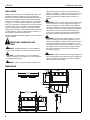
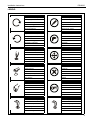
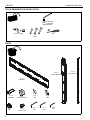
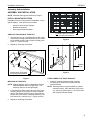
INSTALLATION INSTRUCTIONS
Instrucciones de instalación
Installationsanleitung
Instruções de Instalação
Istruzioni di installazione
Installatie-instructies
Instructions d´installation
Heavy Duty Fixed Wall Mount
Spanish Product Description
German Product Description
Portuguese Product Description
Italian Product Description
Dutch Product Description
French Product Description
PSH2000
PSH2000
DISCLAIMER
Milestone AV Technologies and its affiliated corporations and
subsidiaries (collectively "Milestone"), intend to make this
manual accurate and complete. However, Milestone makes no
claim that the information contained herein covers all details,
conditions or variations, nor does it provide for every possible
contingency in connection with the installation or use of this
product. The information contained in this document is subject
to change without notice or obligation of any kind. Milestone
makes no representation of warranty, expressed or implied,
regarding the information contained herein. Milestone assumes
no responsibility for accuracy, completeness or sufficiency of
the information contained in this document.
Chief® is a registered trademark of Milestone AV Technologies.
All rights reserved.
Installation Instructions
follow all instructions can result in serious personal injury,
damage to equipment, or voiding of factory warranty! It is the
installer’s responsibility to make sure all components are
properly assembled and installed using the instructions
provided.
WARNING: Failure to provide adequate structural strength
for this component can result in serious personal injury or
damage to equipment! It is the installer’s responsibility to
make sure the structure to which this component is attached
can support five times the combined weight of all equipment.
Reinforce the structure as required before installing the
component. The wall to which the mount is being attached
may have a maximum drywall thickness of 5/8" (1.6cm).
WARNING: Exceeding the weight capacity can result in
serious injury or death if you do not follow the instructions.
serious personal injury or damage to equipment! It is the
installer’s responsibility to make sure the combined weight of
all components located between the PSH2000 up to (and
including) the display does not exceed 300 lbs (137 kg). Use
with products heavier than the maximum weight indicated
may result in collapse of the mount and its accessories
causing possible injury.
CAUTION: A CAUTION alerts you to the possibility of
WARNING: Make sure the latches securing the display are
damage or destruction of equipment if you do not follow the
corresponding instructions.
fully closed at all times except when removing or installing the
display. The latches must be fully closed when installing or
removing cables from the display.
IMPORTANT WARNINGS AND
CAUTIONS!
WARNING: A WARNING alerts you to the possibility of
WARNING: Failure to read, thoroughly understand, and
DIMENSIONS
2
Installation Instructions
PSH2000
LEGEND
Tighten Fastener
Pencil Mark
Apretar elemento de fijación
Marcar con lápiz
Befestigungsteil festziehen
Stiftmarkierung
Apertar fixador
Marcar com lápis
Serrare il fissaggio
Segno a matita
Bevestiging vastdraaien
Potloodmerkteken
Serrez les fixations
Marquage au crayon
Loosen Fastener
Drill Hole
Aflojar elemento de fijación
Perforar
Befestigungsteil lösen
Bohrloch
Desapertar fixador
Fazer furo
Allentare il fissaggio
Praticare un foro
Bevestiging losdraaien
Gat boren
Desserrez les fixations
Percez un trou
Phillips Screwdriver
Adjust
Destornillador Phillips
Ajustar
Kreuzschlitzschraubendreher
Einstellen
Chave de fendas Phillips
Ajustar
Cacciavite a stella
Regolare
Kruiskopschroevendraaier
Afstellen
Tournevis à pointe cruciforme
Ajuster
Open-Ended Wrench
Remove
Llave de boca
Quitar
Gabelschlüssel
Entfernen
Chave de bocas
Remover
Chiave a punte aperte
Rimuovere
Steeksleutel
Verwijderen
Clé à fourche
Retirez
By Hand
Optional
A mano
Opcional
Von Hand
Optional
Com a mão
Opcional
A mano
Opzionale
Met de hand
Optie
À la main
En option
Hex-Head Wrench
Security Wrench
Llave de cabeza hexagonal
Llave de seguridad
Sechskantschlüssel
Sicherheitsschlüssel
Chave de cabeça sextavada
Chave de segurança
Chiave esagonale
Chiave di sicurezza
Zeskantsleutel
Veiligheidssleutel
Clé à tête hexagonale
Clé de sécurité
3
PSH2000
Installation Instructions
TOOLS REQUIRED FOR INSTALLATION
3/16" (included)
5/32" (included)
M5 (included)
7/32" (5.5mm)
#2
1/2"
13mm
PARTS
B (2)
[vertical bracket]
A (2)
[wall plate]
D (6)
M8x25mm
H (6)
M8
4
E (6)
[mounting button]
J (24)
5/16-18 x 1/2"
F (6)
M8
K (1)
M5
G (6)
M8
L (1)
3/16"
M (1)
1/8"
C (2)
[side support]
Installation Instructions
PSH2000
Assembly And Installation
ASSEMBLY AND INSTALLATION
NOTE: Read the Warnings and Cautions on page 2.
INSTALL MOUNTING BUTTONS
Installation of the mounting buttons is dependent on your
specific display. Three options are provided:
•
•
•
Akira 84" and Orion 84" displays
Modular 84" displays
Other large flat panel displays
Install buttons (E) at these
6 mounting hole locations.
AKIRA 84" AND ORION 84" DISPLAYS
1. Using M5 hex key (K), insert M8x25mm button head
cap screw (D) through mounting button (E) and install
into threaded mounting hole on back of display (See
Figure 1). Tighten securely.
Figure 2
2. Repeat for remaining five buttons.
(E)
(E)
Mounting Hole
(D)
(H)
(G)
(F)
Modular
Frame
(D)
Install buttons (E) at these
6 mounting hole locations.
Figure 1
MODULAR 84" DISPLAYS
NOTE: Modular displays are four independent displays
attached together within a single frame. The
assembly performs as a single display.
1. Insert M8x25mm button head cap screw (D) through
mounting button (E) and frame on back of modular
display (See Figure 2)(See Figure 3). Using M5 hex
key (K) and 13mm wrench, install M8 washer (F), M8
lock washer (G), and M8 nut (H). Tighten securely.
Figure 3
OTHER LARGE FLAT PANEL DISPLAYS
1. Install the optional interface bracket to display
according to the instructions provided with the
interface bracket.
NOTE: Mounting buttons are pre-installed on optional
interface bracket. PSH-2000 items (D) through
(H), and key (K)(See Figure 1), will not be used
with optional interface bracket.
2. Repeat for remaining five buttons.
5
PSH2000
Installation Instructions
ASSEMBLE SIDE SUPPORTS
1. Using 3/16" hex key (L), loosely install side support
(C) to wall plate (A) with 5/16-18 x 1/2" button head
cap screws (J) (See Figure 4). Ensure lip of support
(C) covers edge of plate (A).
16" studs
Centered between 2 studs
Lag Bolt &
Washer
(8 Places)
2. Repeat for other 3 corners.
3. Once all screws (J) are installed, tighten securely.
(J)
(A)
Centered between 3 studs
Lag Bolt &
Washer
(8 Places)
(C)
Figure 5
24" studs
Figure 4
Left of center installation
Lag Bolt & Washer
(8 Places)
INSTALL MOUNT TO WALL
1. Determine approximate mounting location, keeping in
mind the display size.
WARNING: The mount must be installed on two or
three wood studs (or other equivalent vertical or
horizontal supporting framework). Do not mount to
single wood studs. Failure to properly install unit can
result in serious personal injury or damage to
equipment!
2. Use a stud sensor to locate applicable wood studs.
Mark locations with a pencil.
3. Level mount at desired height per one of the
configurations below:
NOTE: Either configuration below provides ± 2" of lateral
shift.
•
•
16" on center studs: The mount is approximately
centered between two or three studs as shown.
(See Figure 5)
24" on center studs: The mount is offset to the left
or right of center between two studs as shown.
(See Figure 6)
4. Using mount as a template, mark the location of the
pilot holes. Ensure the following:
•
•
6
Marks are in the center of wood studs.
8 pilot holes are marked (one in each slot).
Right of center installation
Lag Bolt &
Washer
(8 Places)
Figure 6
NOTE: For 16" on center, 3 stud installation: Lag bolts
and washers on center stud are optional.
5. Drill pilot holes using a 7/32" drill bit. Ensure pilot
holes are straight.
6. Using 1/2" wrench, install eight 5/16" x 2 ½" lag bolts
and eight 5/16" washers through mounting holes and
into pilot holes. Tighten all lag bolts.
NOTE: Lag bolts and washers are not supplied.
Installation Instructions
PSH2000
INSTALL STATIC BRACKETS
AKIRA 84", ORION 84", AND MODULAR 84"
DISPLAYS
1. Using 3/16" hex key (L), loosely install vertical
brackets (B) to wall plates (A) with 5/16-18 x 1/2"
button head cap screws (J) (See Figure 7). Ensure
the following:
• Brackets (B) are installed to outside set of
mounting holes, closest to supports (C).
• Brackets (B) are installed so that latches are
towards top of mount.
2. Tighten all 16 screws (J) securely.
2. Using 3/16" hex key (L), loosely install vertical
brackets (B) to wall plates (A) with 5/16-18 x 1/2"
screws (J) according to dimension noted in previous
step. Ensure that brackets (B) are installed so that
the latches are towards the top of the mount.
•
•
•
14" horizontal dimension: Install brackets (B) to
inside set of mounting holes, closest to center of
mount. (See Figure 9)
24" horizontal dimension: Install brackets (B) to
middle set of mounting holes. (See Figure 10)
33" horizontal dimension: Install brackets (B) to
outside set of mounting holes, closest to supports
(C). (See Figure 7)
3. Tighten all 16 screws (J) securely.
(J)
(16 Places)
(J)
(16 Places)
Figure 7
Figure 9
OTHER LARGE FLAT PANEL DISPLAYS
(J)
(16 Places)
1. Determine horizontal dimension between mounting
buttons on back of display (or interface bracket, if
required). (See Figure 8)
Mounting Buttons
(6 buttons shown;
4 buttons similar)
Figure 10
Back of Display
Figure 8
7
PSH2000
Installation Instructions
INSTALL DISPLAY
WARNING: Exceeding the weight capacity can result in
serious personal injury or damage to equipment! It is the
installer’s responsibility to make sure the combined weight of
all components located between the PSH2000 up to (and
including) the display does not exceed 300 lbs (137 kg). Use
with products heavier than the maximum weight indicated
may result in collapse of the mount and its accessories
causing possible injury.
Six
Button
Installation
Four
Button
Installation
WARNING: Display is very heavy! Ensure display can be
safely lifted and maneuvered as required to install on mount.
Failure to take adequate precautions can result in serious
personal injury or damage to equipment!
1. Ensure latches are in fully open (raised) positions by
loosening Phillips screw on top of latch. (See Figure
11)
latch
open position
(B)
Figure 12
3. Lift and maneuver display such that all mounting
buttons (E) fit into button openings on brackets (B).
Lower display firmly into place. Ensure each button
(E) has fully seated in its button opening.
4. Using Phillips screwdriver, tighten Phillips screw until
latch slides into closed position. (See Figure 13)
closed position
Figure 11
2. Note button openings to be used on each bracket (B)
when installing display. (See Figure 12)
Figure 13
5. Repeat for second latch.
6. Connect cables to display as required.
8
Installation Instructions
PSH2000
REMOVE DISPLAY
WARNING: Display is very heavy! Ensure display can
be safely lifted and maneuvered as required to remove
from mount. Failure to take adequate precautions can
result in serious personal injury or damage to
equipment!
1. Disconnect all cables from display.
2. Using Phillips screwdriver, fully remove top Phillips
screw from threaded hole in bracket (B). (See Figure
14)
threaded hole
in bracket
threaded hole in latch
Figure 14
3. Re-install screw into threaded hole in latch. Turn
screw until latch slides into fully open position.
4. Repeat for second latch.
5. Lift and maneuver display mounting buttons (E) out of
button openings.
9
PSH2000
10
Installation Instructions
Installation Instructions
PSH2000
11
PSH2000
Installation Instructions
USA/International
Europe
Chief Manufacturing, a products division
of Milestone AV Technologies
8805-002017 Rev 00
2011 Milestone AV Technologies, a
Duchossois Group Company
www.chiefmfg.com
03/11
Asia Pacific
A
P
F
A
P
F
A
8401 Eagle Creek Parkway, Savage, MN 55378
800.582.6480 / 952.894.6280
877.894.6918 / 952.894.6918
Fellenoord 130 5611 ZB EINDHOVEN, The Netherlands
+31 (0)40 2668620
+31 (0)40 2668615
Office No. 1 on 12/F, Shatin Galleria
18-24 Shan Mei Street
Fotan, Shatin, Hong Kong
P 852 2145 4099
F 852 2145 4477