1
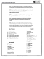
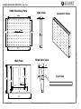
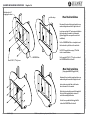
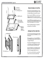
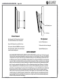
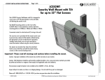
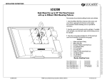
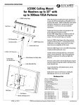
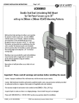
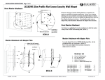
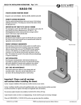
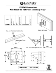
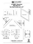
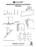
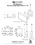
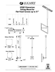
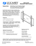
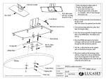
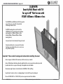
LC6X4WTM INSTALLATION INSTRUCTIONS Page 1 of 6
Protected under one or more of these U.S. Patent numbers: 3,291,432 3,559,942 3,724,798 DES.270,689 4,613,109 4,878,645 4,852,842 DES.309,5624,973,023 5,169,114 5,255,884 5,310,152 5,522,576 5,621,614 Re.35,677
DES.398,834 5,826,384 5,941,492 5,964,068 6,060,661 6,102,398 6,158,704 6,454,116B1 6,761,276B2 6,806,425B1
LC6X4WTM
Security Wall Mount with Tilt
for up to 60" Flat Screens with
VESA® 600mm x 400mm or less
The LC6X4WTM Security Wall Mount with Tilt is designed to
secure a flat screen, up to a 60", to the wall while
still allowing the monitor to tilt.
The VESA® mounting patterns on the front of the
LC6X4WT allow it to be mounted to monitors that have
mounting patterns of 600mm x 400mm or smaller
(including 400mm x 200mm and 200mm x 200mm
mounting patterns)
Convenient cutouts for electrical and A/V wiring in the wall.
Using the provided security screws prevents the monitor
from being removed without the use of a security screw
tool, purchased separately.
Important! Please read all warnings and cautions before installing the mount.
Caution: Improper installation of this mount may void the warranty on your monitor.
Caution: Wall attachment should be performed by qualified installers only, using construction methods prescribed
by authorized architects or engineers that comply to all applicable codes and standards.
The maximum weight of monitor to be installed on the LC6X4WTM is 150 Lbs. (68.2Kg.)
Inspect all parts to make sure there is no shipping damage. Do not install if any parts are damaged.
Please call 1-800-LUCASEY or 1-510-534-1435 if you have any questions about this installation.
LC6X4WTM (9/09)
©2009 Lucasey Manufacturing Corporation, Oakland, California
www.lucasey.com
WARNING: Improper installation can result in serious personal injury. It is the responsibility of the installer to ensure
that all safety precautions are taken during the installation and that all safety features of the mount are properly utilized.
WARNING: The structure to which the mount is attached needs to be capable of supporting five times the stated load limit.
Additional reinforcement of the structure may be necessary and a certified architect
or engineer is needed to make this determination.
WARNING: Take into consideration the combined weight of the mount, the monitor and any auxiliary equipment when
determining the total load on the wall and mount.
WARNING: Do not place your fingers between movable parts on the LC6X4WTM mount. The LC6X4WTM Back Plate
and VESA Mounting Plate, when adjusting the tilt or putting the monitor in place, create pinch points that can
cause injury.
WARNING: Make sure that the screws used to attach the monitor to the mount are the appropriate size and length. An
assortment of monitor attaching screws are provided for convenience. The appropriate screws to use for mounting the
monitor is determined by the monitor manufacturer. Failure to use the screws recommended by the monitor manufacturer
can result in the monitor dropping from the mount and/or damage to the electronic components inside the monitor.
Item List
Table of Contents
Page 1
Page 2
Page 3
Page 4
Page 5
Page 6
...
...
...
...
...
...
Title Page & Product Description
Warnings, Item List & Tools Required
Dimensional Drawings
Installation Instructions for LC6X4WTM Wall Plate
Installation Instructions for Monitor Attachment
Tilt Adjustment, Monitor Removal & Warranty
Tools Required
Stud Finder
Drill with 1/8"Drill Bit
Phillips Screw Driver
1/4" Socket Driver w/ 1/4" Socket
1/4"Socket Extension 12" - 16"
5/32" Hex Driver for 1/4" Socket
(optional security tool 5/32" Hex
Driver with hole for 1/4" Socket)
LC6X4WTM (9/09)
1 ...
1 ...
2 ...
8 ...
4 ...
6 ...
LC6X4WTM Wall Plate
LC6X4WTM VESA Mounting Plate
400mm Spacers
#10-24 x 1" Socket Head Cap Screws
#10-24 x 3/8" Button Head Screw with Security Pin
#14 x 2-1/2" HWH Lag Screws
Monitor Attaching Screw Assortment
4 ...
8 ...
4 ...
8 ...
4 ...
8 ...
4 ...
8 ...
24 ...
12 ...
12 ....
4mm x 40mm Set Screws
4mm Hex Nuts
5mm x 40mm Set Screws
5mm Hex Nuts
6mm x 40mm Set Screws
6mm Hex Nuts
8mm x 40mm Set Screws
8mm Hex Nuts
5mm Flat Washers
8mm Flat Washers
1/4" Flat Washers
©2009 Lucasey Manufacturing Corporation, Oakland, California
www.lucasey.com
Protected under one or more of these U.S. Patent numbers: 3,291,432 3,559,942 3,724,798 DES.270,689 4,613,109 4,878,645 4,852,842 DES.309,5624,973,023 5,169,114 5,255,884 5,310,152 5,522,576 5,621,614 Re.35,677
DES.398,834 5,826,384 5,941,492 5,964,068 6,060,661 6,102,398 6,158,704 6,454,116B1 6,761,276B2 6,806,425B1
LC6X4WTM INSTALLATION INSTRUCTIONS Page 2 of 6
VESA Mounting Plate
600mm
17.7"
17.5"
50mm
Wall Plate
13.75"
15.75"
LC6X4WTM (9/09)
Side View
12°
Max
Isometric View
2.5"
400mm
24.4"
Tilted Side View
6.0"
Tilt
©2009 Lucasey Manufacturing Corporation, Oakland, California
Top View
6.0"
16.0"
24.6"
www.lucasey.com
Protected under one or more of these U.S. Patent numbers: 3,291,432 3,559,942 3,724,798 DES.270,689 4,613,109 4,878,645 4,852,842 DES.309,5624,973,023 5,169,114 5,255,884 5,310,152 5,522,576 5,621,614 Re.35,677
DES.398,834 5,826,384 5,941,492 5,964,068 6,060,661 6,102,398 6,158,704 6,454,116B1 6,761,276B2 6,806,425B1
LC6X4WTM INSTALLATION INSTRUCTIONS Page 3 of 6
Page 4 of 6
Electrical and/or A/V
wiring plug box cutout
This end up.
Wood Stud Installation
Determine the best possible viewing location for your
monitor taking into account the tilt angle to be used.
Locate two wood studs 16" apart using a stud finder in
the location where the monitor is to be mounted.
(Optional Toggle Bolts are required for metal stud
installations)
Use the LC6X4WTM Back Plate as a template to mark
the locations for six pilot holes in the wood studs.
Drill 2-3/4" deep pilot holes using a 1/8" drill bit
in the six marked locations.
LC6X42WTM Back
#14 X 2-1/2" Lag Screws
Use the provided #14 x 2-1/2" Lag Screws to attach
the LC6X4WTM Back Plate to the wall.
Metal Stud Installation
(Using optional WMATB3 Toggle Bolt Kit)
Determine the best possible viewing location for your
monitor taking into account the tilt angle to be used.
Locate a stud using a stud finder in the location
where the monitor is to be mounted.
Follow the instructions that come with the toggle bolt
kit to install the toggle bolt plastic retainers at
each of the mounting hole locations.
Use the Screws provided with the toggle bolt kit
to attach the LC6X4WTM Back to the wall.
LC6X4WTM (9/09)
©2009 Lucasey Manufacturing Corporation, Oakland, California
www.lucasey.com
Protected under one or more of these U.S. Patent numbers: 3,291,432 3,559,942 3,724,798 DES.270,689 4,613,109 4,878,645 4,852,842 DES.309,5624,973,023 5,169,114 5,255,884 5,310,152 5,522,576 5,621,614 Re.35,677
DES.398,834 5,826,384 5,941,492 5,964,068 6,060,661 6,102,398 6,158,704 6,454,116B1 6,761,276B2 6,806,425B1
LC6X4WTM INSTALLATION INSTRUCTIONS
4PL. Hex Nuts
4PL. Flat Washers
4PL. 40mm Long Setscrews
4PL. Security Screws
Determine which type of monitor attaching hardware is required
for the monitor as specified by the monitor manufacturer. Various
sizes of monitor attaching screws are provided for convenience.
LC6X4WTM Front Plate
Make sure the top of the LC6X4WTM Front is oriented in the same
direction as the top of the monitor. The holes on the side of the
LC6X4WTM Front Plate are closer to the bottom edge than the top edge.
2PL. Spacers to allow
cord access and air flow
to vents on back of monitor
Align the LC6X4WTM front plate with the VESA mount pattern on the
back of the monitor. Attach the LC6X4WTM Front Plate to the back of
the monitor using the appropriate size screws and washers.
Monitor with
600mm Wide x
400mm Tall
Mounting Pattern
LC6X4WTM Back Plate
Monitor Attachment to Front Plate
Make sure all of the Monitor Attaching Screws are tight before
proceeding with the rest of the installation.
Attaching Front Plate to Back Plate
Screw four of the provided Socket Head Screws into the threaded
inserts closest to the monitor on the LC6X4WTM Front. Leave 1/2"
of thread exposed.
With two people, lift the monitor, with attached LC6X4WTM Front,
onto the LC6X4WTM Back making sure that the Socket Head Screws
are engaging the Mounting Slots.
Using a long extension and the appropriate security socket tool
or socket head driver, insert the Tilt Adjusting Screws and Pivot
Screws into the threaded inserts farthest from the monitor.
4PL. Socket Head Screws
LC6X4WTM (9/09)
Remove the Socket Head Screws, only after making sure the Tilt
Adjusting Screws and Pivot Screws are installed. Adjust the tilt
to the desired viewing angle and tighten all four screws.
Note: Security Screws and Socket Head Screws are provided for
convenience. Either can be used to safely install the mount.
©2009 Lucasey Manufacturing Corporation, Oakland, California
www.lucasey.com
Protected under one or more of these U.S. Patent numbers: 3,291,432 3,559,942 3,724,798 DES.270,689 4,613,109 4,878,645 4,852,842 DES.309,5624,973,023 5,169,114 5,255,884 5,310,152 5,522,576 5,621,614 Re.35,677
DES.398,834 5,826,384 5,941,492 5,964,068 6,060,661 6,102,398 6,158,704 6,454,116B1 6,761,276B2 6,806,425B1
LC6X4WTM INSTALLATION INSTRUCTIONS Page 5 of 6
Page 6 of 6
Tilt Adjusting Screws
Pivot Screws
Monitor Removal
Tilt Adjustment
Adjust the monitor tilt to 0 and insert four Socket Head
Screws into the threaded inserts closest to the monitor.
Loosen the Tilt Adjusting Screws
Remove the Tilt Adjustment Screws and the Pivot Screws.
Lift the monitor with attached LC6X4WTM Front and separate
the front from the back. Carefully set the monitor down and
remove the monitor attaching screws.
Tilt the monitor to the desired viewing angle.
Tighten the Tilt Adjusting Screws.
LIMITED WARRANTY
LUCASEY MANUFACTURING CORPORATION MAKES NO WARRANTY OF ANY KIND, EXPRESS OR IMPLIED except that the goods sold under this agreement
shall be free of defects in materials and workmanship for a period of one year from the user's date of purchase. User assumes all risk and liability
resulting from the use of the goods, whether used singly or in combination with other goods. Lucasey Manufacturing Corporation neither assumes
nor authorizes any person to assume for it any other liability in connection with the sale or use of the goods sold and there are no oral agreements
or warranties collateral to or affecting this limited warranty. Lucasey Manufacturing Corporation will repair or replace defective parts or equipment
within one year of the date of purchase, at its option, provided the part or equipment is returned pre-paid to Lucasey Manufacturing Corporation's
plant. The repaired or replaced part shall be shipped to the user, FOB Lucasey Manufacturing Corporation's plant. NO allowance for outside labor
charges are implied within the terms of this limited warranty. Under no circumstances will Lucasey Manufacturing Corporation be responsible for
special, indirect or consequential damages. The remedies set forth in this Limited Warranty are exclusive and the liability of Lucasey Manufacturing
Corporation with respect to any contract of sale or anything done in connection therewith, whether in contract, in tort, under any warranty or
otherwise shall not, except as expressly provided herein, exceed the price of the equipment or part on which such liability is based. Any damage
caused by the improper use, operation beyond capacity, substitution of parts or equipment not approved by Lucasey Manufacturing Corporation,
improper packaging, failure to observe installation or other instructions, transit, or repair by one other than Lucasey Manufacturing Corporation,
will not be covered by and shall void this Limited Warranty.
LC6X4WTM (9/09)
©2009 Lucasey Manufacturing Corporation, Oakland, California
www.lucasey.com
Protected under one or more of these U.S. Patent numbers: 3,291,432 3,559,942 3,724,798 DES.270,689 4,613,109 4,878,645 4,852,842 DES.309,5624,973,023 5,169,114 5,255,884 5,310,152 5,522,576 5,621,614 Re.35,677
DES.398,834 5,826,384 5,941,492 5,964,068 6,060,661 6,102,398 6,158,704 6,454,116B1 6,761,276B2 6,806,425B1
LC6X4WTM INSTALLATION INSTRUCTIONS