1
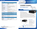
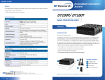
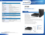
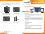
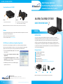
SA1350/ CA1350D/ DT135D
Digital Signage Appliance
Cloud Computing Appliance/ Thin Client
Embedded Controller/ System
Stand Installation for CA1350D
SA1350/ CA1350D/ DT135D
Step 1:
Step 2:
• Remove the two side screws.
• Place the stand, screw and tighten the two M3 x
10mm screws included in the package.
BASIC OPERATION GUIDE
NOTE: If your CA1350D comes with the smart card reader module, make sure the card slot faces up.
Options
This product is designed to work with a range of custom and off-the-shelf options to enhance its
applicability for various deployments.
• Built-in wireless LAN with external antenna
• Smart card reader module (except for SA1350)
SA1350 Server Installation and Appliance Registration
Please refer to the corresponding User Guides for server software installation instructions.
After turning on the SA1350 for the first time, a screen prompt is displayed for registering the
appliance. If the screen prompt is not shown, please follow the instructions below:
1. Press and hold “Control + Shift + Space” to exit the WCM
Player software.
2. Navigate to Start | All Programs | DT Research | WebDT
Signage Player
3. Select Register WebDT Signage Player Again. The Player
Registration screen should appear. Fill in all fields to register.
The required information is marked.
ENGLISH
INTRODUCTION
Thank you for acquiring the latest addition to DT Research’s product line - the SA1350/
CA1350D/ DT135D, featuring compact, robust designs and powered by the high-performance,
energy-efficient AMD Fusion processor. Combined with DT Research’s application-specific
software, these products provide digital signage, cloud computing, or embedded controller
computing solutions. These products also support major embedded operating systems such as
Linux, Microsoft® Windows® XP Embedded, Windows® CE, or Windows® Embedded Standard
7 for a variety of computing needs.
Package Contents
1 One SA1350/ CA1350D/ DT135D
2 AC/DC Power Adapter
3 VESA-compliant Mounting Bracket
4 Quick Start Guide
5 Basic Operation Guide
6 Stand for vertical placement (CA1350D only)
7 Software and User Guide (CA1350 Linux zero client and SA1350 only)
4. Click OK to register and connect to the WebDT Signage
Appliance Publish Server.
1
2000 Concourse Drive, San Jose, CA 95131
http://www.dtresearch.com
Copyright © 2012, DT Research, Inc. All Rights Reserved. DT Research is a registered trademark of DT Research, Inc.
BOG030912DT135ENG
signage dtri com
4
3
6
Note: The actual package contents may vary depending on the product acquired.
DT Research, Inc.
ENGLISH
2
P/N: 28-610-135010 OPERATION GUIDE
SA1350/ CA1350D/ DT135D
Precautions
Device Ports
• Always exercise care when operating and handling.
• Never disassemble any portion of the enclosure. It will void any product warranty.
• Do not use any AC/DC adapter other than the one provided with the device or
acquired from the manufacturer or its partners.
• In the unlikely event that smoke, abnormal noise, or strange odor is present,
immediately power down the product and disconnect all power sources.
The product features an optimal set of I/O ports while preserving the compact size of the
system. The DisplayPort and DVI-I connectors, COM ports, Network (10/100/1000 BaseT
Ethernet), and Power ports are supplemented by a set of four USB 2.0 and two Audio ports.
Through its USB ports, the product supports a wide range of USB-based peripherals. These
peripherals are applicable in providing the means for software installation, application storage,
data storage, and system software recovery and updates.
• Please report the problem to your device provider immediately.
VESA Mounting Bracket Installation Guide
I/O Ports
Front View
A
B
C
The product package includes a VESA-compliant mounting bracket (1) which mounts the
product (2) onto a VESA-compatible monitor or display.
Rear View
D
E
F
G
H
NOTE: The VESA Mounting Bracket is compatible with most displays and monitors that support
the VESA standard.
Step1:
• Locate the existing mounting holes on the monitor.
DC-in
B DisplayPort
C DVI-I port
A
Ethernet port
E Audio jacks (2)
D
Power button
G USB 2.0 (4)
H RS232 COM ports (2)
F
<1>
• Line the bracket holes up with the holes on the back of the
monitor, as shown to the right.
• Place the screws to hold the mounting bracket in place and
tighten the screws (do not over-tighten).
Powering ON and OFF
The Power Button is located in the front of the product. The Power Button may be configured
to function differently depending on the power options of the operating system. In general, to
turn on the product, push and release the Power Button on the front bezel. The adjacent power
LED will be lit (blue) and the corresponding interface will be displayed on the display monitor.
To turn off the device, again depending on software operating system, push and release the
Power Button or use a software shutdown interface. In the event of system lockup, the Power
Button may be used to perform a reset on the device. To do that, push and hold the Power
Button for at least 4 seconds. The system will shut down and all unsaved work may be lost.
Pushing on the Power Button again will restart the device.
NOTE: The SA1350 is programmed to Power On automatically when power is first applied or
re-established.
ENGLISH
2
Step2:
• Remove the two M3 screws (3) originally on the product.
• Place the product (2) on the bracket rail with the interface
ports side facing downwards so that the two mounting
holes on the appliance are aligned with the existing holes
on the rail (see picture).
Step 3:
<2>
<3>
• Apply and tighten the screws into their original locations
and make sure that the bracket and the product are
properly secured.
3
ENGLISH