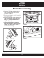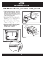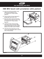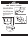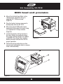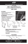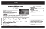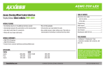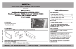
1
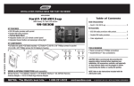
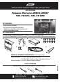
INSTALLATION INSTRUCTIONS FOR PART 99-7612
APPLICATIONS
Nissan Murano 2003-2007
99-7612A, 99-7612B
KIT FEATURES
• DDIN Head unit provisions
• ISO DIN Head unit provision with pocket
• 7612A-Coated with Brushed Aluminum look
• 7612B-Painted Matte Black
KIT COMPONENTS
• A) Radio Housing • B) Radio Housing Brackets • C) Pocket • D) (14) #8 x 3/8” Phillips screws
• E) (2) #8 x 1/2” Phillips screws • F) 7612 wire harness • G) Female 3.5mm Connector w/ Brown and Brown/White Wires
B
C
E
D
F
G
WIRING & ANTENNA CONNECTIONS (Sold Separately)
Wiring Harness: • 70-7550 1995-Up Nissan Harness
• 70-7551 1995-Up Nissan Amp Integration Harness
Antenna Adapter: • 40-NI10 Nissan Antenna Adapter
TOOLS REQUIRED
Panel Removal Tool • Phillips Screwdriver • Socket Wrench
METRA. THE WORLD’S BEST KITS.™
metraonline.com
1-800-221-0932
© COPYRIGHT 2004-2011 METRA ELECTRONICS CORPORATION
REV. 5/9/12
A
99-7612
Table of Contents
Dash Disassembly
– Nissan Murano 2003-2007
3-5
Kit Assembly
– ISO DIN head unit provision with pocket
– DDIN head unit provision
6-7
8-9
SWC Instructions
– Wiring instructions
– SWC button reassignment/remapping
Caution
10-11
12-13
Metra recommends disconnecting the negative battery terminal before beginning any
installation. All accessories, switches, and especially air bag indicator lights must be
plugged in before reconnecting the battery or cycling the ignition.
*NOTE: Refer also to the instructions included with the aftermarket radio.
KNOWLEDGE IS POWER
Enhance your installation and fabrication skills by
enrolling in the most recognized and respected
mobile electronics school in our industry.
Log onto www.installerinstitute.com or call
800-354-6782 for more information and take steps
toward a better tomorrow.
Metra recommends MECP
certified technicians
99-7612
Dash Disassembly
1. Unclip and remove the trim panel
surrounding the display and including
the a/c vents. (Figure A)
2. Remove (2) Phillips screws exposed
behind vent/display trim panel.
(Figure B)
3. Unclip and remove the lower trim panel
around the bottom of the radio panel.
(Figure C)
Continued on next page
(Figure A)
(Figure B)
(Figure C)
3
99-7612
Dash Disassembly
4. Remove (1) Phillips screw per side of
radio chassis exposed behind lower
trim panel. (Figure D)
5. Remove radio/climate control assembly
from the sub dash.
6. Remove (4) Phillips screws securing the
radio chassis to the factory radio trim
panel. Lift up slightly and proceed to
step 7. (Figure E)
7. Unlock the connector on the switch
panel and remove the cable joining the
chassis and switch panel. (Figure F)
(Figure E)
Continued on next page
(Figure F)
Left side
Right side
(Figure D)
4
99-7612
Dash Disassembly
8. Remove the unified meter a/c amp from
radio chassis assembly. (Figure G)
9. Remove (8) Phillips screws securing
the switch panel to the radio trim panel.
Unplug and keep the harness and trim
panel for Kit Assembly. (Figure H)
Continue to kit assembly
(Figure G)
(Figure H)
5
Kit Assembly 99-7612
ISO DIN head unit provision with pocket
1. Trim the shaded areas from the factory
radio trim panel. (Figure A) Do not cut
the locator and screw hole off as they
will be necessary to mount the 99-7612
radio housing. (See detail)
2. Attach the 99-7612 Radio Housing to
the Radio Trim Panel using (4) supplied
3/8” Phillips screws. (Figure B)
3. Mount the Radio Housing Brackets to
the head unit with the screws supplied
with the unit. (Figure C)
(Figure B)
4. Mount the pocket to the radio/bracket
assembly using (4) supplied 3/8”
Phillips screws. (Figure C)
Trim shaded areas
(Figure C)
(Figure A)
Detail
6
Kit Assembly 99-7612
ISO DIN head unit provision with pocket
5. Mount the Unified Amp Meter to the
radio/bracket assembly using
(2) supplied 3/8” Phillips screws.
(Figure D)
6. Plug the factory harness removed in
disassembly into the 99-7612.
7. Mount the whole radio/pocket/meter
assembly to the radio trim panel using
(4) supplied 3/8” Phillips screws.
(Figure E)
8. Locate the factory wiring harness
and antenna plug in the dash. Metra
recommends using the proper mating
adapters from Metra and/or AXXESS.
(Figure D)
9. Follow the wiring instructions in this
manual and reassemble dash in reverse
order of disassembly.
(Figure E)
7
Kit Assembly 99-7612
DDIN head unit provision
1. Trim the shaded areas from the factory
radio trim panel. (Figure A) Do not cut
the locator and screw hole off as they
will be necessary to mount the 99-7612
radio housing. (See detail)
2. Attach the 99-7612 Radio Housing to
the Radio Trim Panel using (4) supplied
3/8” Phillips screws. (Figure B)
3. Slide the Double DIN head unit into the
radio housing brackets and secure with
screws supplied with the unit.
(Figure C)
(Figure B)
Trim shaded areas
(Figure C)
(Figure A)
Detail
8
Kit Assembly 99-7612
DDIN head unit provision
4. Mount the Unified Amp Meter to the
radio/bracket assembly using (2)
supplied 3/8” Phillips screws.
(Figure D)
5. Plug the factory harness removed in
disassembly into the 99-7612.
6. Mount the whole DDIN radio/meter
assembly to the radio trim panel using
(4) supplied 3/8” Phillips screws.
(Figure E)
7. Locate the factory wiring harness in
the dash. Metra recommends using
the proper mating adapter from Metra
or AXXESS. Re-connect the negative
battery terminal and test the unit for
proper operation.
(Figure D)
8. Follow the wiring instructions in this
manual and reassemble dash in reverse
order of disassembly.
(Figure E)
9
99-7612
Wiring Instructions
From the included 7612 harness:
1. Plug the black 16-way connector into the 99-7612.
2. Plug the black 12-way connector into the 99-7612.
3. Plug the white 16-way connector into the factory harness.
Driver Information Center Button Control Note:
The metra kit button layout does not provide the MAINT or the E/M buttons from the factory
setup. MAINT button on the 99-7612 is accessed by pressing the DAY/NIGHT and HOUR
buttons simultaneously. The E/M button is done by pressing PREV and MIN simultaneously.
SWC Instructions
Plug the 3.5 jack into the aftermarket radio.
NOTE: If using an Eclipse or Kenwood radio, use supplied female 3.5 adaptor
For Kenwood/ late model JVC radios:
• Connect the Kenwood SWC wire (normally Blue/Yellow) to the Brown wire of the
3.5 jack. Isolate and tape the Brown/White wire, it will not be used.
For Eclipse radios:
• Connect the Eclipse SWC wires (normally Brown and Brown/Black) to the Brown
and Brown/White wires of the 3.5 jack. Brown goes to Brown and Brown/White
goes to Brown/Black.
Other model radios connect key one to Brown and key two is not used.
10
99-7612
Wiring Instructions
SWC Programming
After all connections are made, turn ignition and the 7612 buttons will flash the number of
times that correspond with the radio installed (See list below). After the LED goes out test
SWC functions.
Force mapping a radio type
Programming must take place within 20 seconds of turning the ignition on.
1. Hold the Volume Down button on the steering wheel for at least 25-seconds until the
lights on the kit start to flash.
2. Tap volume up to program the radio type. Note: Lights on kit will blink to
corresponding number of button presses. Use the following chart to choose
which type of radio you are programming.
1st LED flash is for Eclipse
2nd LED flash is for Kenwood
3rd LED flash is for Clarion
4th LED flash is for Sony and Dual
5th LED flash is for JVC
6th LED flash is for Pioneer and Jensen
7th LED flash is for Alpine
8th LED flash is for Visteon
9th LED flash is for Valor
10th LED flash is for Clarion 5V
11th LED flash is for Metra OE
3. Once you choose your radio type hold volume down for 5-seconds to finish programming
the steering wheel controls. Note: The kit will confirm the radio type by the number
of times the lights blink.
11
99-7612
SWC Button Reassignment/Remapping
Let’s say you have the 99-7612 programmed to your vehicle and your radio and you want to
change the button assignment for the steering wheel controls. For instance you would like
Seek Up to be Mute.
• The 99-7612 must have detected the vehicle and radio it is attached to before you can
remap any buttons.
• You can only start the remapping of the steering wheel controls process within the first
20-seconds of turning the ignition key on. If you wait longer then the 20-seconds you
will have to turn the ignition off then back on again.
• Within the first 20-seconds if any button other then Volume Up or Volume Down is
pushed, the remapping process will stop.
• If during the remapping process no button is pushed for 30-seconds the remapping
process is aborted and the original settings are reset.
So let’s begin the remapping process:
1. Turning off the radio is recommended.
2. Within the first 20 seconds of turning the ignition on, press and hold down the Volume Up
button for at least 25 seconds.
3. The lights on the 99-7612 will light up solid. Release Volume Up and the lights will go
out. Volume Up has now been programmed.
4. Follow the list below in order however pushing the steering wheel control button you
want for the function below. If you want to skip a command press the Volume Up on the
steering wheel, this will tell the 99-7612 to skip the command and go to the next one.
1. Volume Up
6. Mute
11. Play/Enter
16. Fan Down
2. Volume Down
7. Preset Up
12. PTT (Push To Talk)
17. Temp Up
3. Seek Up/Next
8. Preset Down
13. On Hook
18. Temp Down
4. Seek Down/Prev
9. Power
14. Off Hook
5. Source/Mode
10. Band
15. Fan Up
* Note: Remember not all radios will have all these commands. Please refer to
the radios’ owners manual for specific commands recognized by the radio.
Continued on next page
12
99-7612
SWC Button Reassignment/Remapping
For instance the next command to be mapped is the Volume Down command. Let’s say
you want the Mode button on your steering wheel to be the Volume Down command.
Hold down the Mode button till the LED lights up solid red, and then release it.
Now your Mode button on the steering wheel is Volume Down.
5. After the last button is programmed on your steering wheel (you do not have to go
through the whole list), hold down the Volume Up button for at least 10-seconds
then the led will go out.
Or
After the 18th button is programmed or skipped the LED will go out and the
remapping is completed.
13
Notes
Notes
REV. 5/9/12
INSTALLATION INSTRUCTIONS FOR PART 99-7612
METRA. THE WORLD’S BEST KITS.™
metraonline.com
1-800-221-0932
© COPYRIGHT 2004-2011 METRA ELECTRONICS CORPORATION