1
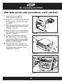
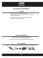
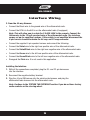
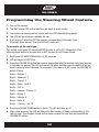
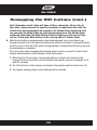
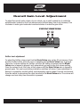
INSTALLATION INSTRUCTIONS FOR PART 99-3012
APPLICATIONS
Chevy Sonic 2012-up
99-3012G
KIT FEATURES
• ISO DIN Head unit provision with pocket
• DDIN Head unit provisions
• Painted Gray to match factory finish
• Interface included retains factory OnStar, Bluetooth,
steering wheel controls, and all warning chimes.
• Provides a 12-volt accessory power and VSS,
Parking Brake, and Reverse signals.
KIT COMPONENTS
• A) Radio Trim Panel • B) Radio Brackets • C) Pocket • D) (4) #8 x 3/8” Phillips truss-head screws • E) Panel Clips
• F) Interface • G) 20-pin harness • H) 4-pin harness w/stripped leads • I) 22-pin to 44-pin harness
• J) Female 3.5mm Connector w/ Brown and Brown/White Wires
B
C
D
G
H
E
F
I
J
4 pin
WIRING & ANTENNA CONNECTIONS (Sold Separately)
Wiring Harness: • Interface included
Antenna Adapter: • 40-EU55 multi-use antenna adapter
TOOLS REQUIRED
Panel Removal Tool • Phillips Screwdriver • Socket Wrench
METRA. THE WORLD’S BEST KITS.™
metraonline.com
1-800-221-0932
© COPYRIGHT 2004-2011 METRA ELECTRONICS CORPORATION
REV. 3/6/12
A
99-3012G
Table of Contents
Dash Disassembly
– Chevy Sonic 2012-up
3
Kit Assembly
– ISO DIN head unit provisions with pocket
– DDIN head unit provisions
4
5
Interface Installation
–
6-15
Caution
Metra recommends disconnecting the negative battery terminal before beginning any
installation. All accessories, switches, and especially air bag indicator lights must be
plugged in before reconnecting the battery or cycling the ignition.
*NOTE: Refer also to the instructions included with the aftermarket radio.
KNOWLEDGE IS POWER
Enhance your installation and fabrication skills by
enrolling in the most recognized and respected
mobile electronics school in our industry.
Log onto www.installerinstitute.com or call
800-354-6782 for more information and take steps
toward a better tomorrow.
Metra recommends MECP
certified technicians
99-3012G
Dash Disassembly
1. Using a panel removal tool, unsnap and
remove the panel surrounding the radio
(vents above radio included). (Figure A)
2. Unclip and remove the factory A/C vents
from the radio trim panel.
3. Remove four 7mm screws to remove
the radio. (Figure B )
Continue to kit assembly
(Figure A)
(Figure B)
3
Kit Assembly 99-3012G
ISO DIN head unit provision with pocket
1. Install factory vents into the
radio trim panel. (Figure A)
2. Install the four included panel clips onto
the appropriate locations of the radio
trim panel.
3. Mount the pocket to the radio brackets
with the (4) #8 x 3/8” Phillips screws
supplied. (Figure B)
4. Slide the head unit into radio brackets
and secure with screws supplied with
the radio. (Figure B)
(Figure A)
5. Locate the factory wiring harness
and antenna plug in the dash. Metra
recommends using the proper mating
adapters from Metra and/or AXXESS.
Test the unit for operation.
6. Mount the new radio assembly into
the dash, snap-in the radio panel, and
reassemble dash in reverse order of
disassembly. (Figure C)
(Figure B)
(Figure C)
4
Kit Assembly 99-3012G
Double DIN head unit provisions
1. Install factory vents into the
radio trim panel. (Figure A)
2. Install the four included panel clips onto
the appropriate locations of the radio
trim panel.
3. Slide the Double DIN head unit into the
radio housing brackets and secure with
screws supplied with the unit.
(Figure B)
4. Locate the factory wiring harness
and antenna plug in the dash. Metra
recommends using the proper mating
adapters from Metra and/or AXXESS.
Test the unit for operation.
(Figure A)
5. Mount the new radio assembly into
the dash, snap-in the radio panel, and
reassemble dash in reverse order of
disassembly. (Figure C)
(Figure B)
(Figure C)
5
99-3012G
Axxess Interface
FEATURES
• Retains amplified or non-amplified systems.
• Retains factory OnStar, Bluetooth, steering wheel controls,
and all warning chimes.
• Provides a 12 volt 10 amp accessory output and VSS,
Parking Brake, and Reverse signals.
INTERFACE COMPONENTS
Axxess interface • 4-pin harness with stripped leads
20-pin harness • 22-pin to 44-pin harness
Female 3.5mm connector with Brown and Brown/White wires
TOOLS REQUIRED
• Cutting tool • Crimping tool • Tape • Connectors (butt-connectors, bell caps, etc.)
ISO
M4
M3.5
IGNITION
TERMINALS
M2.6
M3
6
2.5
WIRE
CUTTER
1.5
M5
6
99-3012G
Interface Wiring
1. From the 20-pin harness
• Connect the Red wire to the ignition/accessory wire of the aftermarket radio.
• Connect the Orange/White wire to the illumination wire of the aftermarket radio. If the
aftermarket radio has no illumination wire just tape off the Orange/White wire.
• Connect the Blue/White wire to the amp turn on wire of the aftermarket radio.
• Connect the Brown wire to the mute wire of the aftermarket radio. If the aftermarket
radio does not have a Mute wire, tape up the Brown wire.
NOTE: If the radio shuts off when OnStar is activated even though the Mute wire
is connected, you may need to add a resistor between the switched 12V wire and
the mute line. We suggest 10K ohms. If the radio still shuts off, you may want to
reduce the resistor value. If the radio mutes at inappropriate times (such as when
the lights are switched on or off), the resistor value may need to be increased.
• The Black/Yellow wire will be discussed later on in the instructions.
For Non-amplified Systems
• Connect the White wire to the left front positive speaker output of the aftermarket radio.
• Connect the White/Black wire to the left front negative speaker output of the
aftermarket radio.
• Connect the Gray wire to the right front positive speaker output of the after market radio.
• Connect the Gray/Black wire to the right front negative speaker output of the
aftermarket radio.
7
99-3012G
Interface Wiring
For Amplified Systems
• Connect the White RCA to the left front low level output of the aftermarket radio.
• Connect the Gray RCA to the right front low level output of the aftermarket radio.
• Connect the Green RCA to the left rear low level output of the aftermarket radio.
• Connect the Violet RCA to the right rear low level output of the aftermarket radio.
The following wires are for NAV or media type aftermarket radios:
• Connect the Green wire to the parking brake wire of the aftermarket navigation radio.
• Connect the Blue/Pink wire to the VSS or speed sense wire of the aftermarket
navigation radio.
• Connect the Green/Purple wire to the reverse wire of the aftermarket navigation radio.
2. From the 22-way Harness
• Connect the Black wire with the ring terminal to the back of the aftermarket
radio chassis.
• Connect the 3.5mm jack to your aftermarket radios steering wheel control input
(if equipped).
Note: If using an Eclipse or Kenwood radio, use supplied female a 3.5 adaptor.
* For Kenwood radios: Connect the Kenwood SWC wire (normally Blue/Yellow) to the
Brown wire of the ASWC. Isolate and tape the Brown/White wire, it will not be used.
* For Eclipse radios: Connect the Eclipse SWC wires (Normally Brown and Brown/Black)
to the Brown and Brown/White wires of the ASWC. Brown connected to Brown and
Brown/White connected to Brown/Black.
8
99-3012G
Interface Wiring
3. From the 44-way Harness:
• Connect the Black wire to the ground wire of the aftermarket radio.
• Connect the RCA’s to the AUX in on the aftermarket radio (if equipped)
Note: This will allow you to retain the 3.5 AUX JACK in the console. Connect the
Yellow wire to the 12-volt constant wire of the aftermarket radio. The interface
comes set up for amplified systems. If the vehicle is not amplified disconnect the
4-pin harness located between the 44-way and 22-way connector.
• Connect the supplied 4-pin speaker harness and connect the following:
• Connect the Violet wire to the right rear positive wire of the aftermarket radio.
• Connect the Violet/Black wire to the right rear negative wire of the aftermarket radio.
• Connect the Green wire to the left rear positive wire of the aftermarket radio.
• Connect the Green/Black wire to the left rear negative wire of the aftermarket radio.
• Disregard the Pink wire. It is not used in this application.
Installing the Interface
1. With all the connections completed, plug the 20- and 22-pin harnesses
into the interface.
2. Reconnect the negative battery terminal.
3. Plug the 44-pin GM harness into the vehicle side harness, and plug the
aftermarket radio harness into the aftermarket radio.
Note: Continue to the TESTING THE INTERFACE section if you do not have factory
audio controls on the steering wheel.
9
99-3012G
Programming the Steering Wheel Controls
1. Turn on the ignition.
2. The SWC status LED on the interface will begin to blink rapidly.
3. Tap volume up steering wheel control until the LED stops blinking rapidly.
4. The LED will go off when it detects the car.
5. It will then will blink the LED the number corresponding to the radio type.
(See radio types below). Then the LED will remain off.
To manually set the radio type:
This action must begin 20-seconds AFTER the Key is set to ACC ON position OR a
steering wheel button is pressed that is NOT Volume Up nor Volume Down.
1. Hold Down VOLUME DOWN button for 30-seconds
2. LED will begin to FAST blink
3. Press the VOLUME UP button the number associated with the desired radio type (as seen
in the radio list below). The LED will remain ON while holding down the button & will go
back to blinking when released. For example: If the radio is a JVC, press the VOLUME UP
button 5 times.
Radio – Eclipse 1
Radio – Kenwood 2
Radio – Clarion 3
Radio – Sony – Dual 4
Radio – JVC 5
Radio – Jensen – Pioneer 6
Radio – Alpine 7
Radio – Visteon 8
Radio – Valor 9
Radio – Clarion – 5K 10
4. Press the VOLUME DOWN button to finish. The LED will then go off.
5. After a few seconds, the LED will then blink the number of times corresponding to the
radio ID type. This number should be the same number the user has just pressed the
VOLUME UP button.
10
99-3012G
To Force the unit to retry to
auto-detect the radio
This action must begin 20-seconds AFTER the key is set to ACC ON position OR a steering
wheel button is pressed that is NOT Volume Up nor Volume Down.
1. Hold Down VOLUME UP button for 30-seconds.
2. LED will go ON to indicate auto-detecting. (button can be released now)
3. After about 6-seconds, LED will go OFF indicating completion.
4. The LED will then blink the number of times corresponding to the radio ID type it has
detected. (See Radio chart above)
Note: Not every aftermarket radio will have all of the possible SWC commands on
the steering wheel. Aftermarket radios that do not have Bluetooth features will not
recognize the PTT (Push to Talk) or On Hook/Off Hook commands.
Please refer to the radios owners’ manual or wireless remote for specific
commands the radio will recognize.
Testing the Interface
With the vehicle battery re-connected, cycle the key on and off once and back on. Turn the
ignition on, and then turn the aftermarket radio on. Push the OnStar button, the radio should
turn off (radio will mute if mute wire is connected) and you should hear OnStar. Push the
OnStar cancel button and the radio should come back on. Cycle the a/c fan speed all the
way to high and back to low when you first install the kit.
Chime/Turn Signal Volume Adjustment
To adjust the chime volume, use a small screwdriver to rotate the potentiometer,
located on the 8-pin harness side of the interface (closest to 8-pin harness).
Turn clockwise to make the chime/turn signal louder and counterclockwise to
make the chime/turn signal softer.
Note: Turn signal will not be affected in non-amplified systems.
11
99-3012G
Remapping the SWC buttons
Let’s say you have the SWC programmed to your vehicle and your radio and you want to
change the button assignment for the steering wheel controls.
For instance you would like Seek Up to be Mute.
First a few notes:
• The SWC must have detected the vehicle and radio it is attached to before you can
remap any buttons.
• You can only start the remapping of the steering wheel controls process within the first
20-seconds of turning the ignition key on. If you wait longer than the 20-seconds you
will have to turn the ignition off then back on again.
• Within the first 20-seconds if any button other then Volume Up or Volume Down is
pushed, the remapping process will stop.
• If during the remapping process no button is pushed for 30-seconds the remapping
process is aborted and the original settings are reset.
So let’s begin the remapping process:
1. Ideally having the interface visible is recommended since you can see the
LED flashes to confirm button recognition.
2. Turning off the radio is recommended
3. Within the first 20-seconds of turning the ignition on, press and hold down the
Volume Up button for at least 25-seconds.
4. The led will light up solid red. Release Volume Up and the LED will go out. Volume Up
has now been programmed.
5. Follow the list below in order however pushing the steering wheel control button you
want for the function below. If you want to skip a command press the Volume Up on the
steering wheel, this will tell the interface to skip the command and go to the next one.
1. Volume Up
6. Mute
11. Play/Enter
2. Volume Down
7. Preset Up
12. PTT (Push To Talk)
3. Seek Up/Next
8. Preset Down
13. On Hook
4. Seek Down/Prev
9. Power
14. Off Hook
5. Source/Mode
10. Band
12
99-3012G
Remapping the SWC buttons (cont.)
Note: Remember not all radios will have all these commands. Please refer to
the radios’ owners manual for specific commands recognized by the radio. For
instance the next command to be mapped is the Volume Down command. Let’s
say you want the Mode button on your steering wheel to be the Volume Down
command. Hold down the Mode button till the led lights up solid red, and then
release it. Now your Mode button on the steering wheel is Volume Down.
6. After the last button is programmed on your steering wheel (you do not have to go
through the whole list), hold down the Volume Up button for at least 10 seconds then the
led will go out or after the 18th button is programmed or skipped the LED will go out and
the remapping is completed.
If for any reason after remapping the steering wheel controls you want to return to the
original steering wheel control settings, follow these steps:
1. Within the first 20-seconds of turning the ignition on. Press and hold down the
original Volume Down button (not the Volume Down button you just remapped) for at
least 25-seconds.
2. The LED will turn on then release the Volume Down button and the led will turn off.
3. The original steering wheel control settings will be restored.
13
99-3012G
Overall Gain Level Adjustment
To adjust the overall audio volume of your vehicle, use a small screwdriver to rotate the
potentiometer, located on the 8-pin harness side (furthest away from 8-pin harness). Turn
clockwise to make gain louder and counterclockwise to make the gain softer.
POTENTIOMETERS
OnStar level adjustment
To adjust the OnStar volume level find the Black/Yellow wire on the 20-pin harness. Push
the blue OnStar button, while the voice is speaking tap the Black/Yellow wire to ground.
There are 4 volume settings for OnStar; once the 4th setting is reached and the Black/
Yellow wire is tapped to ground it will automatically go back to the first volume setting.
Once the volume is set it will stay at that volume until the Black/Yellow wire is tapped to
ground again. This can be set during installation and then left alone. If user adjustment is
desired, a momentary contact switch (sold separately) can be added. Connect one terminal
from the switch to ground and the other terminal to the Black/Yellow wire. The volume will
change one level every time the switch is pressed.
14
99-3012G
Vehicle customization with optional LCD
(AXXESS part # XIA-LCD sold separately)
The OEM radio is used to customize certain features of the vehicle.
Use the optional lcd to adjust these features accordingly:
1. Press the ESC button and PRESS ENTER TO SET LANGUAGE will appear on the screen.
2. To change the LANGUAGE press the ENTER button then press then press the UP and
DOWN buttons to change the LANGUAGE.
3. Once you have chosen you LANGUAGE then press ESC to go back to be able to scroll
through the other settings.
4. If you do not wish to change the LANGUAGE you can scroll up and down through the
different settings with the UP and DOWN buttons.
5. Remember to press ENTER to change the desired setting.
15
REV. 3/6/12
INSTALLATION INSTRUCTIONS FOR PART 99-3012
METRA. THE WORLD’S BEST KITS.™
metraonline.com
1-800-221-0932
© COPYRIGHT 2004-2011 METRA ELECTRONICS CORPORATION