1
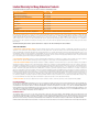
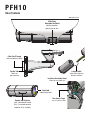
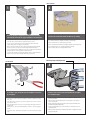
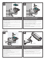
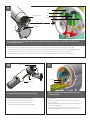
© 2012, Moog Videolarm, Inc. All Rights Reserved
PFH10
Outdoor Tubular Dust-Proof and Pressurized Environmental Housings
www.moogvideolarm.com
Installation and Operation Instructions for the following models:
PFH10C2W An Pressurized tubular housing, 24Vac or 12Vdc input, heater & blower with feed-thru wall / pole mount
PFH10C2WY
Pressurized tubular housing, 24Vac or 12Vdc input, heater & blower with feed-thru wall / pole mount, adjustable sunshield
PFH10C8WY
Pressurized tubular housing, PoE input with Dynamic Power Allocation, 30 watt
midspan included, heater & blower with feed-thru wall / pole mount, supports .af PoE cameras, adjustable sunshield
DFH10C2W Dust-Proof tubular housing, 24Vac or 12Vdc input, heater & blower with feed-thru wall / pole mount
DFH10C2WY Dust-Proof tubular housing, 24Vac or 12Vdc input, heater & blower with feed-thru wall / pole mount, adjustable sunshield
DFH10C8WY Dust-Proof tubular housing, PoE input with Dynamic Power Allocation, 30
watt midspan included, heater & blower with feed-thru wall / pole mount, supports .af PoE cameras, adjustable sunshield
Before attempting to connect or operate this product, please read these instructions completely.
81-IN5480
06-18-2012
IMPORTANT SAFEGUARDS
1
Read these instructions.
2
Keep these instructions.
3
Heed all warnings
4
Follow all instructions.
5
Do not use this apparatus near water.
6
Clean only with damp cloth.
7
CAUTION
RISK OF ELECTRIC SHOCK
DO NOT OPEN
Do not block any of the ventilation openings. Install in accordance with the
manufacturers instructions.
8
9
SAFETY PRECAUTIONS
Cable Runs- All cable runs must be within permissible distance.
CAUTION: TO REDUCE THE RISK OF
ELECTRIC SHOCK, DO NOT REMOVE
COVER ( OR BACK). NO USER- SERVICEABLE PARTS INSIDE. REFER SEVICING
TO QUALIFIED SERVICE PERSONNEL.
Mounting - This unit must be properly and securely mounted to a supporting
structure capable of sustaining the weight of the unit.
Accordingly:
a. The installation should be made by a qualified installer.
b. The installation should be in compliance with local codes.
c. Care should be exercised to select suitable hardware to install the unit, taking into
account both the composition of the mounting surface and the weight of the unit.
10 Do not install near any heat sources such as radiators, heat registers, stoves, or other
apparatus ( including amplifiers) that produce heat.
11 Do not defeat the safety purpose of the polarized or grounding-type plug. A
polarized plug has two blades with one wider than the other. A grounding type
plug has two blades and a third grounding prong. The wide blade or the third
prong are provided for your safety. When the provided plug does not fit into your
outlet, consult an electrician for replacement of the obsolete outlet.
12 Protect the power cord from being walked on or pinched particularly at plugs,
convenience receptacles, and the point where they exit from the apparatus.
13 Only use attachment/ accessories specified by the manufacturer.
14 Use only with a cart, stand, tripod, bracket, or table specified by the manufacturer,
or sold with the apparatus. When a cart is used, use caution when moving the cart/
apparatus combination to avoid injury from tip-over.
15 Unplug this apparatus during lighting storms or when unused for long periods of time.
16 Refer all servicing to qualified service personnel. Servicing is required when the
apparatus has been damaged in any way, such as power-supply cord or plug is
damaged, liquid has been spilled of objects have fallen into the apparatus, the
The lightning flash with an arrowhead symbol,
within an equilateral triangle, is intended to
alert the user to the presence of non-insulated
“dangerous voltage” within the product’s
enclosure that may be of sufficient magnitude
to constitute a risk to persons.
Este símbolo se piensa para alertar al usuario a la presencia
del “voltaje peligroso no-aisIado” dentro del recinto de los
productos que puede ser un riesgo de choque eléctrico.
Ce symbole est prévu pour alerter I’utilisateur à la presence
“de la tension dangereuse” non-isolée dans la clôture de
produits qui peut être un risque de choc électrique.
Dieses Symbol soll den Benutzer zum Vorhandensein der
nicht-lsolier “Gefährdungsspannung” innerhalb der
Produkteinschließung alarmieren die eine Gefahr des
elektrischen Schlages sein kann.
Este símbolo é pretendido alertar o usuário à presença “di
tensão perigosa non-isolada” dentro do cerco dos produtos
que pode ser um risco de choque elétrico.
Questo simbolo è inteso per avvertire I’utente alla presenza
“di tensione pericolosa” non-isolata all’interno della
recinzione dei prodotti che può essere un rischio di scossa
elettrica.
apparatus has been exposed to rain or moisture, does not operate normally, or
has been dropped.
Be sure to periodically examine the unit and the supporting structure to make sure that the integrity
of the installation is intact. Failure to comply with the foregoing could result in the unit separating
from the support structure and falling, with resultant damages or injury to anyone or anything struck
by the falling unit.
UNPACKING
Unpack carefully. Electronic components can be
damaged if improperly handled or dropped. If an item
appears to have been damaged in shipment, replace
it properly in its carton and notify the shipper.
Be sure to save:
1 The shipping carton and packaging material.
They are the safest material in which to make future
shipments of the equipment.
2 These Installation and Operating Instructions.
SERVICE
If technical support or service is needed, contact us at
the following number:
TECHNICAL SUPPORT
AVAILABLE 24 HOURS
1 - 800 - 554 -1124
The exclamation point within an equilateral
triangle is intended to alert the user to
presence of important operating and
maintenance (servicing) instructions in the
literature accompanying the appliance.
Este símbolo del punto del exclamation se piensa para
alertar al usuario a la presencia de instrucciones importantes
en la literatura que acompaña la aplicación.
Ce symbole de point d’exclamation est prévu pour alerter
l’utilisateur à la presence des instructions importantes dans
la littérature accompagnant l’appareil.
Dieses Ausruf Punktsymbol soll den Benutzer zum
Vorhandensein de wichtigen Anweisungen in der Literatur
alarmieren, die das Gerät begleitet.
Este símbolo do ponto do exclamation é pretendido alertar o
usuário à presença de instruções importantes na literatura
que acompanha o dispositivo.
Questo simbolo del punto del exclamaton è inteso per
avvertire l’utente alla presenza delle istruzioni importanti nella
letteratura che accompagna l'apparecchio.
Limited Warranty for Moog Videolarm Products
Moog Videolarm warrants these products to be free from defects in material or workmanship as follows:
PRODUCT CATEGORY
PARTS \ LABOR
AllEnclosuresandElectronics*
Five(5)Years
Poles/PolEvators™/CamEvator
Three(3)Years
WarriorSeries™/Q-View™/IRIlluminators
Five(5)Years
SViewSeries™
Five(5)Years**6monthsifusedinautoscan/touroperation
Controllers
Five(5)Years
PowerSupplies
Five(5)Years
EcoKit
Three(3)Years
AccessoryBrackets
Five(5)Years
LibertyDome
Three(3)Years
*DeputyDome™,NiteTrac™,IglooDome,PurgeDome™
Three(3)Years**6monthsifusedinautoscan/touroperation
During the labor warranty period, to repair the Product, Purchaser will either return the defective product, freight prepaid, or deliver it to Moog Videolarm
Inc. Decatur GA. The Product to be repaired is to be returned in either its original carton or a similar package affording an equal degree of protection with
a RMA # (Return Materials Authorization number) displayed on the outer box or packing slip. To obtain a RMA# you must contact our Technical Support
Team at 800.554.1124, extension 101. Moog Videolarm will return the repaired Product freight prepaid to Purchaser. Moog Videolarm is not obligated to
provide Purchaser with a substitute unit during the warranty period or at any time. After the applicable warranty period, Purchaser must pay all labor and/or
parts charges.
The limited warranty stated in these product instructions is subject to all of the following terms and conditions.
TERMS AND CONDITIONS
1. NOTIFICATION OF CLAIMS: WARRANTY SERVICE: If Purchaser believes that the Product is defective in material or workmanship, then written notice with an
explanation of the claim shall be given promptly by Purchaser to Moog Videolarm. All claims for warranty service must be made within the warranty period.
If after investigation Moog Videolarm determines the reported problem was not covered by the warranty, Purchaser shall pay Moog Videolarm for the cost of
investigating the problem at its then prevailing per incident billable rate. No repair or replacement of any Product or part thereof shall extend the warranty period
of the entire Product. The specific warranty on the repaired part only shall be in effect for a period of ninety (90) days following the repair or replacement of that
part or the remaining period of the Product parts warranty, whichever is greater.
2. EXCLUSIVE REMEDY: ACCEPTANCE: Purchaser’s exclusive remedy and Moog Videolarm’s sole obligation is to supply (or pay for) all labor necessary to repair any
Product found to be defective within the warranty period and to supply, at no extra charge, new or rebuilt replacements for defective parts.
3. EXCEPTIONS TO LIMITED WARRANTY:Moog Videolarm shall have no liability or obligation to Purchaser with respect to any Product requiring service during the
warranty period which is subjected to any of the following: abuse, improper use, negligence, accident, lightning damage or other acts of God (i.e., hurricanes,
earthquakes), modification, failure of the end-user to follow the directions outlined in the product instructions, failure of the end-user to follow the maintenance
procedures recommended by the International Security Industry Organization, written in product instructions, or recommended in the service manual for the
Product. Furthermore, Moog Videolarm shall have no liability where a schedule is specified for regular replacement or maintenance or cleaning of certain parts
(based on usage) and the end-user has failed to follow such schedule; attempted repair by non-qualified personnel; operation of the Product outside of the
published environmental and electrical parameters, or if such Product’s original identification (trademark, serial number) markings have been defaced, altered,
or removed. Moog Videolarm excludes from warranty coverage Products sold AS IS and/or WITH ALL FAULTS and excludes used Products which have not
been sold by Moog Videolarm to the Purchaser. All software and accompanying documentation furnished with, or as part of the Product is furnished “AS IS”
(i.e., without any warranty of any kind), except where expressly provided otherwise in any documentation or license agreement furnished with the Product. Any
cost associated with removal of defective product and installation of replacement product is not included in this warranty.
4. PROOF OF PURCHASE:The Purchaser’s dated bill of sale must be retained as evidence of the date of purchase and to establish warranty eligibility.
DISCLAIMER OF WARRANTY
EXCEPT FOR THE FOREGOING WARRANTIES, Moog Videolarm HEREBY DISCLAIMS AND EXCLUDES ALL OTHER WARRANTIES, EXPRESS OR IMPLIED,
INCLUDING, BUT NOT LIMITED TO ANY AND/OR ALL IMPLIED WARRANTIES OF MERCHANTABILITY, FITNESS FOR A PARTICULAR PURPOSE AND/OR
ANY WARRANTY WITH REGARD TO ANY CLAIM OF INFRINGEMENT THAT MAY BE PROVIDED IN SECTION 2-312(3) OF THE UNIFORM COMMERCIAL
CODE AND/OR IN ANY OTHER COMPARABLE STATE STATUTE. Moog Videolarm HEREBY DISCLAIMS ANY REPRESENTATIONS OR WARRANTY THAT
THE PRODUCT IS COMPATIBLE WITH ANY COMBINATION OF NON-Moog Videolarm PRODUCTS OR NON-Moog Videolarm RECOMMENDED PRODUCTS
PURCHASER MAY CHOOSE TO CONNECT TO THE PRODUCT.
LIMITATION OF LIABILITY
THE LIABILITY OF Moog Videolarm, IF ANY, AND PURCHASER’S SOLE AND EXCLUSIVE REMEDY FOR DAMAGES FOR ANY CLAIM OF ANY KIND
WHATSOEVER, REGARDLESS OF THE LEGAL THEORY AND WHETHER ARISING IN TORT OR CONTRACT, SHALL NOT BE GREATER THAN THE ACTUAL
PURCHASE PRICE OF THE PRODUCT WITH RESPECT TO WHICH SUCH CLAIM IS MADE. IN NO EVENT SHALL Moog Videolarm BE LIABLE TO PURCHASER
FOR ANY SPECIAL, INDIRECT, INCIDENTAL, OR CONSEQUENTIAL DAMAGES OF ANY KIND INCLUDING, BUT NOT LIMITED TO, COMPENSATION,
REIMBURSEMENT OR DAMAGES ON ACCOUNT OF THE LOSS OF PRESENT OR PROSPECTIVE PROFITS OR FOR ANY OTHER REASON WHATSOEVER.
PFH10
Value Features
Optional Accessory
Multi-Plane
Adjustable SunShield
position to protect
against glare on lens
Cable Feed Through
hides and protects cables
Pop Out Tabs
allows for
pole mounting Lanyard Cable
safely retains housing
during installation
Installers Connection Board
allows for easy hook-ups
Hand Hold
underlaid grip point
Durable and Attractive
“grite” color powder coated
finish. (increased corrosion
protection finish available)
Rear Access Panel
acts as internal J-Box
!
Electrical Specifications
Contents of Box
PFH10
Power 12VDC
Class 2 Only
24Vac
12Vdc
29W
11W
(No camera)
(No camera)
English
24Vac
12Vdc
29W
11W
(Ninguna cámara)
(Ninguna cámara)
24Vac
12Vdc
29W
11W
(Aucun appareil-photo)
(Aucun appareil-photo)
24Vac
12Vdc
29W
11W
(Keine Kamera)
(Keine Kamera)
24Vac
12Vdc
29W
11W
(Nenhuma câmera)
(Nenhuma câmera)
24Vac
12Vdc
29W
11W
Midspan
for
Some Models
Español
Français
Deutsch
Portuguese
(Nessuna macchina fotografica)
(Nessuna macchina fotografica)
Italiano
ADDITIONAL DETAIL TO BE UPDATED IN FUTURE REVISIONS
!
Proper Assembly of Mounting Bracket
CAUTION: When assembling the mounting bracket, make sure
all the wiring access holes are facing towards the rear of the
base mounts access portal.
• PRECAUCIÓN: Al montar la consola de montaje, cerciórese de que todos los agujeros
de acceso del cableado son revestimiento hacia la parte posterior del portal bajo del
acceso de los montajes.
• ATTENTION : En assemblant le support, assurez-vous que toutes les ouvertures
d'accès de câblage sont revêtement vers l'arrière du portail bas d'accès de bâtis.
• VORSICHT: Wenn Sie die Schienenplatte zusammenbauen, stellen Sie sicher, dass alle
VerdrahtungsZugangslöcher Einfassung in Richtung zur Rückseite des niedrigen
Einfassungszugangsportals sind.
Wiring Access Holes:
Must be rear facing
Recommended Hardware for the Mounting Holes:
• 5/16” - 18 (or M8 for metric) x minimum 1 ¼” Hex Head Bolt
• 5/16” Flat Washer
• 5/16” Lock Washer
• CUIDADO: Ao montar o suporte, certifique-se que todos os furos de acesso da fiação
são revestimento para a parte traseira do portal baixo do acesso das montagens.
• ATTENZIONE: Nel montare il montaggio - la staffa, si assicura che tutti i fori di
accesso dei collegamenti siano rivestimento verso la parte posteriore del portale
basso di accesso dei supporti.
WALL MOUNTING
1
2
If you are running a conduit to the housing instead of through
mount wiring, first install the appropriate fitting to the wall mount.
Attach mount to wall with suitable hardware (not provided).
• Si usted está funcionando con un conducto a la cubierta en vez del cableado directo
del montaje, primero instale la guarnición apropiada al montaje de la pared.
• Ate el montaje a la pared con el hardware conveniente (no proporcionado).
• Si vous courez un conduit au logement au lieu du câblage traversant de bâti, installez
d'abord l'ajustage de précision approprié sur le bâti de mur.
• Bringen Sie Einfassung zur Wand mit der verwendbaren Hardware an (nicht bereitgestellt).
• Wenn Sie ein Rohr zum Gehäuse anstelle von der durchgehenden Einfassungsverdrahtung
laufen lassen, bringen Sie zuerst die passende Befestigung zur Wandeinfassung an.
• Attachez le bâti au mur avec le matériel approprié (non fourni).
• Una a montagem à parede com a ferragem apropriada (não fornecida).
• Attacchi il supporto alla parete con fissaggi adatti (non forniti).
• Se você está funcionando uma canalização à carcaça em vez da fiação direta da montagem,
instale primeiramente o encaixe apropriado à montagem da parede.
• Se stiate facendo funzionare un condotto all'alloggiamento anziché i collegamenti diretti del
supporto, in primo luogo installi il montaggio adatto al supporto della parete.
Mounting Straps Sold Separately
POLE MOUNTING
4
3
TAB
Reference view of mount after removing the tabs and adding
the wall mount straps.
If attaching to pole, first break away tabs with pliers and remove
(4) strap plugs.
•
Refiérase a la vista del montaje después de quitar las lengüetas y de agregar las correas
del montaje de la pared .
•
Mettez en référence la vue du bâti après avoir enlevé les étiquettes et avoir ajouté les
courroies de bâti de mur.
• Bei der Befestigung zum Pfosten, brechen erste weg Vorsprünge mit Zangen und entfernen
(4) Bügelstecker.
• Se unindo ao pólo, o primeiros quebram afastado abas com alicates e removem (4) plugues
da cinta.
•
Beziehen Sie Ansicht der Einfassung, nachdem Sie die Vorsprünge entfernt haben und
die Wandeinfassungsbügel addiert haben.
•
Proveja a vista da montagem após ter removido as abas e ter adicionado as cintas da
montagem da parede.
• Se attaccando al palo, i primi rompono via le linguette con le pinze e rimuovono (4) la cinghia
tappa.
•
Riferisca la vista del supporto dopo l'eliminazione delle linguette e l'aggiunta delle cinghie
del supporto della parete .
• Si atan al poste, el primeros rompen lejos lengüetas con los alicates y quitan (4) los enchufes
de la correa.
• Si attachant au poteau, les premiers cassent loin des étiquettes avec des pinces et enlèvent
(4) des prises de courroie.
Pole Mount Option (Use Steel Straps to Mount)
5
6
Gasket Nipples
Crimp
Cable Ties
Cable
Cable
Feed cable through bracket, pierce the gasket nipples
(as needed). Place the gasket as shown.
Crimp the connectors as needed. Then use cable ties
on the nipples to secure device, leave extra cable.
•
Alimente el cable a través del soporte, perfore las entrerroscas de la junta (según lo necesitado).
Coloque la junta como se muestra.
•
Prense los conectadores según lo necesitado. Entonces utilice las ataduras de cables en las
entrerroscas para asegurar el dispositivo, dejan el cable adicional.
•
Alimentez le câble par la parenthèse, percez les mamelons de garniture (comme nécessaire).
Placez la garniture comme montrée.
•
Sertissez par replis les connecteurs comme nécessaires. Utilisez alors les serres-câble sur les
mamelons pour fixer le dispositif, laissent le câble supplémentaire.
•
Ziehen Sie Kabel durch Haltewinkel ein, durchbohren Sie die Dichtungsnippel (wie gebraucht).
Setzen Sie die Dichtung wie gezeigt.
•
Quetschverbinden Sie die Verbindungsstücke, wie gebraucht. Benutzen Sie dann Kabelbinder
auf den Nippeln, um Vorrichtung zu sichern, lassen Extrakabel.
•
Alimente o cabo através do suporte, perfure os bocais da gaxeta (como necessário). Coloc a
gaxeta como mostrada.
•
Frise os conectores como necessários. Use então cintas plásticas nos bocais para fixar o
dispositivo, deixam o cabo extra.
•
Alimenti il cavo tramite la staffa, perfori gli ugelli della guarnizione (come stato necessario).
Disponga la guarnizione come indicata.
•
Unisca i connettori come stati necessari. Allora utilizzi le fascette ferma-cavo sugli ugelli per
assicurare il dispositivo, lasciano il cavo supplementare.
Wall Mount Option
7
8
Crimp
(A-Tighten)
Cable
Entry
Cable
Entry
(B-Keep loose until step 6)
OR
Place the housing on the bracket, use the provided captive
screws and the key to mount.
Feed cable through back of bracket or bottom access point.
Then follow instructions from previous block.
•
Alimente el cable a través detrás del soporte o del punto de acceso inferior. Entonces siga las
instrucciones del bloque anterior.
•
Coloque la cubierta en el soporte, utilice los tornillos prisioneros proporcionados y la llave
al montaje.
•
Alimentez le câble à travers en arrière de la parenthèse ou du point d'accès inférieur. Suivez
alors les instructions du bloc précédent .
•
Placez le logement sur la parenthèse, employez les vis captives fournies et la clef au bâti.
•
Setzen Sie das Gehäuse am Haltewinkel, verwenden Sie die zur Verfügung gestellten
Sicherheitsschrauben und den Schlüssel zur Einfassung.
•
Coloc a carcaça no suporte, use os parafusos prisioneiros fornecidos e a chave à montagem.
•
Disponga l'alloggiamento sulla staffa, usi le viti prigioniere fornite e la chiave al supporto.
•
Ziehen Sie Kabel durch zurück des Haltewinkels oder des unteren Zugangspunktes ein.
Befolgen Sie dann Anweisungen vom vorhergehenden Block .
•
Seja o cabo completamente do suporte ou do ponto de acesso inferior. Siga então instruções
do bloco precedente.
•
Alimenti il cavo attraverso indietro della staffa o del punto di accesso inferiore. Allora segua le
istruzioni dal blocco precedente .
9
Communication
Power
(B- Completely loosen)
BNC
RJ45 (568B)
(A- Slightly loosen)
In order to rotate the rear cover, slightly loosen the screw marked (A) and completely loosen the screw marked (B). Then make all of the
nessecary wiring connections.
•
Para girar la cubierta posterior, afloje levemente el (a) marcado tornillo y afloje totalmente el (b) marcado tornillo. Entonces haga todas las conexiones nessecary del cableado.
•
Afin de tourner la couverture arrière, détachez légèrement le (a) marqué par vis et détachez complètement le (b) marqué par vis. Établissez alors tous les rapports nessecary de câblage.
•
Um die hintere Abdeckung zu drehen, lösen Sie etwas das Schraube signifikante (a) und lösen Sie vollständig das Schraube signifikante (b). Stellen Sie dann alle nessecary Verdrahtungsbeziehungen her.
•
A fim girar a tampa traseira, afrouxe ligeiramente o (a) marcado parafuso e afrouxe completamente o (b) marcado parafuso. Faça então todas as conexões nessecary da fiação.
•
Per girare la copertura posteriore, allenti un po'la vite contrassegnata (A) e completamente allenti la vite contrassegnata (B). Allora faccia tutti collegamenti nessecary dei collegamenti.
10
(A)
(A)
(A) 2 long screws
11
Key (B) 1 lower screw
Connectors
Lanyard Cable
Cable
Reference inside view for showing board, flying cables and
attached connectors.
Use provided Key to remove the front part of the housing.
•
El uso proporcionó llave para quitar la parte delantera de la cubierta.
•
L'utilisation a fourni la clef pour enlever la partie avant du logement.
•
Gebrauch lieferte Schlüssel, um das Vorderteil des Gehäuses zu entfernen.
•
O uso forneceu a chave para remover a parte dianteira da carcaça.
•
L'uso ha fornito la chiave per rimuovere la parte anteriore dell'alloggiamento.
•
Refiérase dentro de la visión para demostrar el tablero, los cables que vuelan y los
conectadores atados.
•
Mettez en référence à l'intérieur de la vue pour montrer le conseil, les câbles volants et
les connecteurs attachés.
•
Beziehen Sie innerhalb der Ansicht für das Zeigen des Brettes, der fliegenden Kabel und
der angebrachten Verbindungsstücke.
•
Proveja dentro da vista para mostrar a placa, cabos de voo e conectores unidos.
•
Riferimento all'interno della vista per la mostra bordo, i cavi volanti e dei connettori allegati.
Reference Block [15]
12
Reference Block [15]
13
NOTE:
The power distribution board is designed with a 24Vac / 12Vdc
selector switch. If the Switch is set at 24Vac, then voltage input
should be 24Vac. 24Vac will then be output to the camera. If the
Switch is set at 12Vdc, then voltage input should be 12Vdc, 12Vdc
will then be output to the camera. The selector switch is to allow
the housing to operate at either voltage.
•
•
•
El tablero de distribución de energía está diseñado con un selector de 24 Vac / 12 Vdc. Si el
interruptor se ha fijado en 24 Vac,entonces la tensión de entrada debe ser 24 Vac. 24 Vac será
entonces la salida de la cámara. Si el interruptor se ha fijado en 12 Vcc, entonces la tensión de
entrada debe ser de 12 Vdc, 12 Vdc a continuación será la salida a la camera. Selector es
permitir a la vivienda para operar a cualquier voltaje.
Le tableau de distribution électrique est conçu avec un interrupteur 24Vac / 12Vdc sélecteur.
Si le commutateur est fixé à 24Vac, puis la tension d'entrée doit être 24Vac. 24Vac sera alors
sortie de la caméra. Si le commutateur est fixé à 12 Vdc, puis la tension d'entrée doit être
12Vdc, 12Vdc sera alors la sortie de l'interrupteur de sélection camera. Est de permettre
le logement de fonctionner à la tension soit.
Die Stromverteilungsplatine wird mit einer 24 Vac / 12Vdc Wahlschalter konzipiert. Wenn
der Schalter auf 24Vac gesetzt ist, dann sollte Spannungseingang 24Vac. Wird 24Vac dann
an der Kamera sein. Wenn der Schalter auf 12Vdc eingestellt ist, dann sollte Spannungseingang
12Vdc, 12Vdc wird dann an den camera. Wahlschalter ist es, dass das Gehäuse entweder
an Spannung zu betreiben sein.
•
O quadro de distribuição de energia é projetado com um interruptor 24Vac / 12 Vdc selector.
Se o interruptor está fixado em 24Vac, depois da tensão de entrada deve ser 24Vac. 24Vac,
então, ser a saída para a câmera. Se o interruptor estiver na 12Vdc, em seguida, entrada de
tensão deve ser 12Vdc, 12Vdc será então a saída para o comutador selector camera. é permitir
que o invólucro para operar em qualquer tensão.
•
La scheda di distribuzione dell'alimentazione è progettato con una 24Vac / 12Vdc selettore. Se
l'interruttore viene fissato a 24 Vac, quindi tensione di ingresso deve essere 24Vac. 24Vac sarà
quindi uscita alla fotocamera. Se l'interruttore viene fissato a 12Vdc, quindi tensione di ingresso
deve essere 12Vdc, 12Vdc sarà poi uscita allo switch camera. Di selezione è quello di permettere
l'alloggiamento di funzionare sia a tensione.
14
WARNING!
Make sure that the Voltage Selector Switch is set for the
correct input and camera supply voltage before power is
supplied. Failure to do this may result in damage to the
housing and void all warranties.
•
Asegúrese de que el selector de tensión está ajustado para la entrada correcta y tensión
de alimentación de la cámara antes de la alimentación se suministra. No hacer esto puede
resultar en daños a la vivienda y anulará todas las garantías.
•
Assurez-vous que le sélecteur de tension est réglé pour l'entrée et la tension d'alimentation
appareil photo avant de l'alimentation est fournie. Le défaut de ce faire peut entraîner des
dommages au logement et annulera toutes les garanties.
•
Stellen Sie sicher, dass der Spannungswahlschalter für die richtige Eingabe und Kamera
Versorgungsspannung eingestellt ist, bevor Strom versorgt wird. Wenn Sie dies nicht tun,
kann es zu Schäden am Gehäuse führen und erlischt jegliche Gewährleistung.
•
Certifique-se de que o seletor de tensão é definido para a entrada correta e tensão de
alimentação da câmera antes de alimentação é fornecida. Não fazer isso pode resultar
em danos à carcaça e anular todas as garantias.
•
Assicurarsi che il selettore di tensione sia impostato per l'ingresso corretto e tensione di
alimentazione della fotocamera prima che l'alimentazione viene fornita. In caso contrario
si possono causare danni al corpo e invalidare tutte le garanzie.
15
24Vac /12Vdc
selector switch
24Vac /12Vdc
selector switch
24Vac
Selectable
24Vac or 12Vdc
power out
to camera
12Vdc
Analog
Video
Alarm / analog
communication
Heater
Network
Data
(-) Input (+)
(-) Output (+)
(-) Fan (+)
} Factory Wiring
The power distribution board is designed with a 24Vac/12Vdc
selector switch. Select the desired input voltage. No other
customer input is needed for this board.
•
The power distribution board is located inside the housing at
the rear.
•
•
El cuadro de distribución de alimentación se encuentra dentro de la carcasa en la parte trasera.
•
•
Le tableau de distribution électrique est situé à l'intérieur du boîtier à l'arrière.
•
Die Stromverteilungsplatine innerhalb des Gehäuses auf der Rückseite.
•
A placa de distribuição de energia está localizado no interior do invólucro na parte traseira.
•
La scheda di distribuzione di potenza è situato all'interno dell'alloggiamento sul retro.
•
•
El tablero de distribución de energía está diseñado con un interruptor selector de 24Vac/12Vdc.
Seleccione el voltaje de entrada deseada. No hay entrada de otro cliente que se necesita para
este foro.
Le tableau de distribution de puissance est conçu avec un commutateur sélecteur de
24Vac/12Vdc. Sélectionnez la tension d'entrée souhaitée. Aucun autre client d'entrée est
nécessaire pour ce conseil.
Die Stromverteilungsplatine ist mit einem Wahlschalter 24Vac/12Vdc- konzipiert. Wählen Sie die
gewünschte Eingangsspannung. Kein anderer Kunde Eingang ist für dieses Board benötigt.
O quadro de distribuição de energia é projetado com um interruptor 24Vac/12Vdc selector.
Seleccionar a tensão de entrada desejado. Nenhuma entrada de outro cliente é necessário para
este fórum.
La scheda di distribuzione di potenza è progettato con un interruttore 24Vac/12Vdc selettore.
Selezionare la tensione di ingresso desiderato. Nessun ingresso altro cliente è necessario per
questa scheda.
17
16
Camera Sled Ring
Screw
Camera Sled
Loosen the screws shown on the picture and turn the camera
sled ring to the desired angle and re-tighten.
Install the camera using provided screws and rubber spacer, to
center lens (if needed).
•
Instale la cámara usando los tornillos proporcionados y el espaciador de goma, a la lente de
centro (si es necesario).
•
Afloje los tornillos demostrados en el cuadro y dé vuelta al anillo del trineo de la cámara
al ángulo deseado y vuélvalo a apretar.
•
Installez l'appareil-photo utilisant les vis fournies et l'entretoise en caoutchouc, sur l'objectif
central (si nécessaire).
•
Desserrez les vis montrées sur l'image et tournez l'anneau de traîneau d'appareil-photo
à l'angle désiré et le resserrez.
•
Bringen Sie die Kamera unter Verwendung der zur Verfügung gestellten Schrauben und der
Gummidistanzscheibe, zum Mittelobjektiv an (wenn erforderlich).
•
Lösen Sie die Schrauben, die auf der Abbildung gezeigt werden und drehen Sie den
Kameraschlittenring zum gewünschten Winkel und ziehen Sie wieder an.
•
Instale a câmera usando os parafusos fornecidos e o espaçador de borracha, à lente center
(se necessário).
•
Afrouxe os parafusos mostrados no retrato e gire o anel do trenó da câmera para o ângulo
desejado e reaperte-o.
•
Stalli la macchina fotografica usando le viti fornite ed il distanziatore di gomma, all'obiettivo
concentrare (se necessario).
•
Allenti le viti indicate sull'immagine e giri l'anello della slitta della macchina fotografica
nell'angolo voluto e riserri.
Pressurize the Unit (NOT required for the Dust Tight Unit)
Future Maintenance
18
19
100
580
Fitting
50
0
150
Air Chuck
200
250
PSI 300
Hose
Regulator
Nitrogen
Tank
HAND HOLD
When pressurizing unit be sure to set the gauge or regulator
slightly above the housing pressure target of 5-7psi (0.35-0.5bar).
The front window can be removed in case the lens
requires adjustment.
•
La ventana delantera puede ser quitada en caso de que la lente requiera el ajuste.
•
La fenêtre avant peut être enlevée au cas où l'objectif exigerait l'ajustement.
•
Das vordere Fenster kann entfernt werden, falls das Objektiv Justage erfordert.
•
A janela dianteira pode ser removida caso que a lente exige o ajuste.
•
La finestra anteriore può essere rimossa nel caso l'obiettivo richieda la registrazione.
•
Al presurizar la unidad esté seguro de fijar el calibrador o el regulador levemente
sobre la blanco de la presión de la cubierta de 5-7psi (0.35-0.5bar).
•
En pressurisant l'unité soyez sûr de placer la mesure ou le régulateur légèrement
au-dessus de la cible de pression de logement de 5-7psi (0.35-0.5bar).
•
Wenn Sie Maßeinheit unter Druck setzen, seien Sie sicher, die Lehre oder den
Regler über das Gehäusedruckziel von 5-7psi (0.35-0.5bar) etwas einzustellen.
•
Ao pressurizar a unidade seja certo ajustar ligeiramente o calibre ou o regulador
acima do alvo da pressão da carcaça de 5-7psi (0.35-0.5bar).
•
Nel pressurizzare l'unità sia sicuro regolare un po'il calibro o il regolatore sopra
l'obiettivo di pressione dell'alloggiamento di 5-7psi (0.35-0.5bar).
Pressurize the Unit Cont.
20
Place the air chuck on the fill valve
and begin filling until pressure relief
valve opens.
•
Coloque la tirada del aire en la válvula del tanque y
comience a llenar hasta que la válvula de descarga
de presión se abra.
•
Placez le mandrin d'air sur la valve de réservoir et
commencez à remplir jusqu'à ce que la valve de
décompression s'ouvre.
•
Setzen Sie die Luftklemme auf das Behälterventil
und fangen Sie an zu füllen, bis Druckablassventil
sich öffnet.
•
Coloc o mandril do ar na válvula do tanque e
comece a encher-se até que a válvula de escape de
pressão abra.
•
Disponga il mandrino dell'aria sulla valvola del carro
armato e cominci a riempire fino a che la valvola
limitatrice della pressione non si apra.
Over Relief Valve
(5-7psi)
Pressure Fill Schraeder Valve
Air Chuck
21
Depress the fill valve. Drain all air
from the housing and repeat 3 times
to remove all moisture.
Pressure Fill Schraeder Valve
Depress to Purge
•
Presione la válvula del terraplén. Salga todo el aire
de la cubierta y de la repetición 3 veces de quitar
toda la humedad.
•
Enfoncez la valve de suffisance. Évacuez tout l'air le
logement et la répétition 3 fois d'enlever toute
l'humidité.
•
Drücken Sie das Fülleventil nieder. Lassen Sie alle
Luft aus dem Gehäuse und der Wiederholung 3mal,
alle Feuchtigkeit zu entfernen ab.
•
Comprima a válvula da suficiência. Saia todo o ar da
carcaça e da repetição 3 vezes remover toda a
umidade.
•
Deprima la valvola del materiale di riempimento.
Tolga tutta l'aria dall'alloggiamento e dalla
ripetizione 3 volte rimuovere tutta l'umidità.
22
After purging and refilling, check
the housings pressure. It should be
around 5-7psi (0.35-0.5bar).
Connectors
Over - Pressure Relief Valve
10
5
0
Fill Valve
15
•
Después de purgar y de rellenar, compruebe la
presión de las cubiertas. Debe estar alrededor de
5-7psi (0.35-0.5bar).
•
Après la purge et le remplissage, vérifiez la pression
de logements. Elle devrait être autour de 5-7psi
(0.35-0.5bar).
•
Nachdem Sie bereinigt haben und wieder gefüllt
haben überprüfen Sie den Gehäusedruck. Er sollte
um 5-7psi (0.35-0.5bar) sein.
•
Após a remoção e o reenchimento, verific a pressão
das carcaças. Deve ser em torno de 5-7psi
(0.35-0.5bar).
•
Dopo l'eliminazione dell'inceppo ed il riempimento,
controlli la pressione degli alloggiamenti. Dovrebbe
essere intorno a 5-7psi (0.35-0.5bar).
20
25
PSI 30
Pressure Gauge
NOT INCLUDED
Air Chuck
Replacement Parts List
16
PFH10
15
7
11
12
4
2
3
1
17
13
8
11
14
6
PART #
5
9
10
1 RPVL3857
2 RPVL3863
3 RPVALV12
4 RPCA3682
5 RPPFHPCK
6 RPVALV08
7 RPVL2968
8 RPGK3880
9 RPVL3858
10 RPFTM2425G
11 RPRSORG24
12 RPVL3860
13 RP76VL2015
14 RPVL2969
15 RPVL2965
16 RPVL3888
17 RPVL2972
DESCRIPTION
BACK COVER
BACK COVER GASKET
TANK VALVE
CONNECTION BOARD
HARDWARE PACKET
PRESSURE RELIEF VALVE
HOUSING BODY
WALL MOUNT GASKET
HOUSING BRACKET
WALL MOUNT BRACKET
HOUSING ORING
HOUSING NUT
PC BOARD
CAMERA SLED ASSEMBLY
HOUSING ASSEMBLY
LANYARD SLED
FRONT WINDOW ASSEMBLY
Product Registration/Warranty
Thank you for choosing Moog Videolarm. We value your patronage and are solely committed to providing you with the highest
quality products available and superior customer service. Should a problem arise, rest assure that Moog Videolarm stands behind its products by offering impressive warranty plans: 3 Years on all Housings, Poles, Power Supplies, and Accessories and 5 Years on camera systems (SView, QView, Warriors), and InfraRed Illuminators.
Register Your Products Online
Take a few moments and validate your purchase via the Online Product Registration Form at
www.videolarm.com/productregistration.jsp
Register your recent Moog Videolarm purchases and benefit from the following:
• Simple and Trouble-Free RMA process
• Added into customer database to receive product updates / news
• Eliminate the need to archive original purchase documents:
Receipts, Purchase Orders, etc…
15