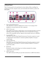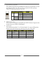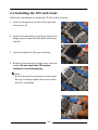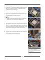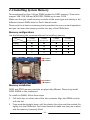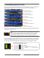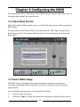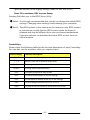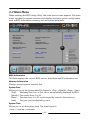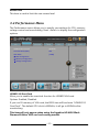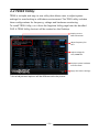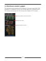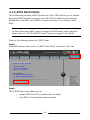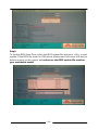
1
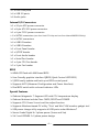
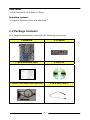
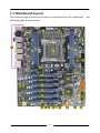
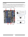
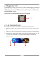
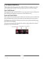
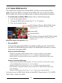
User’s Manual Sapphire Pure Black X79N Intel X79 / LGA 2011 Mainboard TRADEMARK All products and company names are trademarks or registered trademarks of their respective holders. These specifications are subject to change without notice. Manual Revision 1.0 November 14, 2011 Federal Communications Commission (FCC) Statement This device has been tested and found to comply with the limits for a Class B digital device, pursuant to Part 15 of FCC Rules. These limits are designed to provide reasonable protection against harmful interference in a residential installation. This equipment generates, uses and can radiate radio frequency energy and, if not installed and used in accordance with instructions contained in this manual, may cause harmful interference to radio and television communications. However, there is no guarantee that interference will not occur in a particular installation. If this product does cause harmful interference to radio or television reception, which can be determined by turning the equipment off and on, the user is encouraged to try to correct the interference by one or more of the following measures: Reorient or relocate the receiving antenna. Increase the separation between the equipment and receiver. Connect the product into an outlet on a circuit different from that to which the receiver is connected. Consult the dealer or an experienced radio/TV technician for help. ÍNote1: Connecting this device to peripheral devices that do not comply with Class B requirements, or using an unshielded peripheral data cable, could also result in harmful interference to radio or television reception Note2: The user is cautioned that any changes or modifications not expressly approved by the party responsible for compliance could void the user’s authority to operate this product. Note3: To ensure that the use of this product does not contribute to interference, it is necessary to use shielded I/O cables CE: Radiation of EN 55022 & Immunity of EN 55024 Waste Electrical and Electronic Equipment (WEEE) Statement To protect the global environment, this product must be sent to separate collection facilities for recovery and recycling. DISPOSAL Do not dispose of this product as unsorted municipal waste. Collect such waste separately for special treatment. ~ ii ~ Table of Contents Chapter 1 Introduction .............................................................. 1 1-1 Mainboard Specifications ........................................................... 1 1-2 Package Contents ..................................................................... 4 1-3 Mainboard Layout ...................................................................... 5 Chapter 2 Installation ................................................................ 9 2-1 Before You Begin ....................................................................... 9 2-2 Installing the I/O Shield .............................................................. 9 2-3 Securing to the Chassis ............................................................. 9 2-4 Installing the CPU and Cooler .................................................. 10 2-5 Installing System Memory ........................................................ 11 Memory configurations ............................................................. 12 Memory Installation .................................................................. 12 2-6 Installing Expansion Cards ...................................................... 13 2-7 Connecting Cables .................................................................. 15 Connecting Power Supply Cables ............................................ 15 Connecting Serial ATA (SATA) Cables ...................................... 16 Connecting to the Internal Headers and Connectors ............... 17 Front Panel Header ............................................................ 17 USB2.0 Headers ................................................................. 18 USB3.0 Headers ................................................................. 18 CFPA Header ...................................................................... 19 S/PDIF Header ................................................................... 19 Serial Port Header .............................................................. 19 2-8 Diagnostics LED ...................................................................... 21 2-9 LED Status Indicators .............................................................. 21 2-10 Onboard Buttons .................................................................... 21 Clear CMOS Button ................................................................. 22 Reset and Power Button .......................................................... 22 2-11 Dual BIOS Switch ................................................................... 23 Chapter 3 Configuring the BIOS ............................................ 24 3-1 Select Boot Device .................................................................. 24 3-2 Enter BIOS Setup .................................................................... 24 ~ iii ~ 3-3 Main Menu ............................................................................... 26 3-4 Performance Menu .................................................................. 27 CPU Configuration ................................................................... 29 Memory Configuration .............................................................. 30 Voltage Configuration ............................................................... 32 3-5 Advanced Menu ....................................................................... 34 ACPI Settings ........................................................................... 35 CPU Configuration ................................................................... 36 CPU Information ....................................................................... 37 SATA Configuration .................................................................. 38 USB Configuration ................................................................... 39 Super IO Configuration ............................................................. 40 Serial Port 0 Configuration ....................................................... 40 H/W Monitor ............................................................................. 41 Smart Fan Configuration .......................................................... 42 Onboard Device Configuration ................................................. 43 3-6 Chipset Menu ........................................................................... 45 3-7 Boot Menu ............................................................................... 46 3-8 Security Menu .......................................................................... 47 3-9 Save & Exit Menu .................................................................... 48 Chapter 4 Driver Installation ................................................ 50 4-1 Driver Install ............................................................................. 50 4-2 TRIXX Utility ............................................................................ 51 4-3 Hardware monitor gadget ........................................................ 52 4-4 S_BIOS Flash Utility ................................................................ 53 Chapter 5 POST Code .......................................................... 58 ~ iv ~ Chapter 1 Introduction 1-1 Mainboard Specifications CPU Supports Intel® Core i7 3900 and 3800 series processor in LGA2011 package Supports Intel® Turbo Boost technology, Hyper-Threading technology Chipset Intel® X79 with NVIDIA nF200 PCI-E bridge System Memory Four 240-pin DDR3 SDRAM DIMM sockets Supports 1.5v DDR3-1066/ 1333/ 1600+ DIMMs with quad channel architecture Supports x16 and x8 DIMMs, non-ECC, unbuffered DIMMs Supports up to 32GB system memory USB Ports From Intel® X79 chipset: - Ten USB 2.0 ports (six at rear panel, four onboard headers), supporting transfer speed up to 480Mbps From Asmedia USB 3.0 controller: - Six USB 3.0 ports (four at rear and two onboard headers) backward compatible with USB 2.0, supporting transfer speeds up to 4.8Gbps Supports wake-up from S1, S3 and S4 modes Support power charge function - Front panel 2 USB 3.0 ports also support power charge function under S5 mode SATA Ports From Intel® X79 chipset: - Two SATA3 ports with 6Gb/s data transfer rate and four SATA2 ports with 3Gb/s data transfer rate - Supports RAID 0, 1, 10 and 5 functions - Supports AHCI (Advanced Host Controller Interface) ~1~ From Marvell 88SE9128 controller: - Two SATA3 ports with 6Gb/s data transfer rate with RAID 0 and 1 - Supports AHCI (Advanced Host Controller Interface) From Marvell 88SE9172 controller: - Two eSATA3 ports at rear port - Supports AHCI (Advanced Host Controller Interface) Onboard LAN Dual Gigabit Ethernet from Marvell 88E8057 Gigabit controller Bluetooth Atheros AR3011 is a highly integrated, all-CMOS, single chip with Bluetooth® 2.1 + EDR supported Onboard Audio Supports 8-channel High-Definition audio from Realtek ALC892 codec Supports rear panel Optical S/PDIF output Supports Jack-detection function Expansion Slots Six PCI-Express 2.0 x16 slots with PCI-E Slot Disable/Enable Jumper PCI-E slot 1 and PCI-E slot 2 are PCI-E Gen3 ready Supports ATI® CrossFireXTM Technology * Please refer to detail configuration at 2-6 Installing Expansion Cards I/O Onboard Fintek F71889A LPC bus I/O controller Supports Hardware Monitoring for fan speed, CPU and system temperature Back Panel I/O Ports 1 x PS/2 Keyboard/Mouse port 6 x USB 2.0 ports 1 x Coaxial S/PDIF Out connector 1 x Optical S/PDIF Out connector 1 x Bluetooth 2 x eSATA ports ~2~ 2 x RJ45 LAN ports 4 x USB 3.0 ports 6 Audio jacks Internal I/O Connectors 1 x 24-pin ATX power connector 1 x 8-pin ATX 12V power connector 1 x 6-pin PCI-E power connector 4 x SATA3 connectors (two from Intel X79 chip and two from Marvell 88SE9128 chip) 4 x SATA2 connectors 4 x USB2.0 headers 2 x USB3.0 headers 1 x Front Panel header 1 x S/PDIF header 1 x Front Audio header 1 x Serial Port header 1 x 4-pin CPU Fan header 5 x 3-pin Fan header BIOS 64Mb SPI Flash with AMI based BIOS User Friendly graphics interface QBIOS (Quick Control UEFI BIOS) S_BIOS easily update and back up at BIOS control panel Supports ACPI (Advanced Configuration and Power Interface) Dual BIOS switch with on board indicator LEDs Special Features Onboard diagnostic 7-Segment LED with CPU temperature display Onboard buttons include Clear CMOS, RESET and POWER Supports CPU Power Vcore Load-line adjust function Supports Windows based OC utility “Trixx” and Win7 HW monitor gadget tool USB power charge utility supports all USB ports under Windows 7 Server Grade Digital 6+1 phase power (Vcore and Vsa) Vtt 2 and VDIMM 2+2 phase power design ~3~ Form Factor ATX form factor of 305mm x 245mm Operating systems: Supports Windows Vista and Windows 7 1-2 Package Contents Your Sapphire mainboard comes with the following accessories. 1. Mainboard 2. I/O Shield 3. Quick Installation Guide 4. Driver CD 5. USB3.0 Front Panel Cable (Optional) 6. SATA Data Cable *8 ~4~ 1-3 Mainboard Layout The following figure shows the location of components on the mainboard. following page for description. ~5~ See Item Component description 1 CPU Socket 2011 2 Intel X79 Chip 3 NVIDIA nF200 Chip 4 DDR3 DIMM Slots 1-4 5 PCI-E 2.0 x16 Slot *6 6 24-Pin ATX Power Connector 7 8-pin ATX_12V Power Connector 8 6-pin PCI-E Power Connector 9 SATA3 Connectors *4 10 SATA2 Connectors *4 11 Front Panel Header 12 USB 3.0 Header *2 13 USB 2.0 Header *4 14 Power Button 15 Reset Button 16 Clear CMOS Button 17 Serial port Header 18 Front Panel Audio Header 19 S/PDIF Header 20 PCI-E Slot Control Jumper 21 CPU Fan Header 22 3-pin Fan Header *5 23 Mainboard Battery 24 PC Speaker 25 Debug LED Display 26 64Mb SPI Flash 27 Dual BIOS Switch 28 Back Panel Connectors (see below for detail) ~6~ I/O Back Panel The I/O back panel for this mainboard is shown below. When installing the mainboard into the computer case, use the bundled I/O shield to protect this back panel. 1. PS/2 Keyboard/Mouse Port This connector is used for a keyboard or mouse. You can plug a PS/2 keyboard or mouse directly into this connector. 2. USB 2.0 Ports (six) The mainboard provides an OHCI (Open Host Controller Interface) Universal Serial Bus root for attaching USB devices such as a keyboard, mouse or other USB-compatible devices. Supports data transfer rates up to 480Mb/s. 3. Coaxial S/PDIF-Out This SPDIF (Sony & Philips Digital Interconnect Format) connector is used for digital audio transmission to external speakers/amplifier through a coaxial cable. 4. Optical S/PDIF-Out This SPDIF (Sony & Philips Digital Interconnect Format) connector is used for digital audio transmission to external speakers/amplifier through an optical fiber cable. 5. Bluetooth Bluetooth wireless technology is an interface intended for wireless control/data communication 6. eSATA Port (two) The eSATA (External SATA) port provides connection to eSATA hard drives. ~7~ 7. Dual LAN Ports with LEDs The mainboard provides two standard RJ-45 jacks for connecting to a Local Area Network (LAN). Two LEDs are built into the RJ-45 LAN connector. These LEDs indicate the status of the LAN. LED LED Color LED state Off A B Green Indicates LAN link is not established On LAN link is established Blinking LAN activity is occurring N/A Off 10 Mb/s data rate Green On 100 Mb/s data rate Yellow On 1000 Mb/s data rate 8. USB 3.0 ports (four) USB 3.0 ports are backward compatible with USB 2.0 devices. Supports data transfer rates up to 4.8Gb/s (SuperSpeed). 9. Audio ports This mainboard provides 2, 6 or 8 channel audio. It is easy to differentiate between the audio functions by referring to the color of the jacks. Ports Blue 2 channel 6 channel 8 channel Line-In Line-In Line-In Lime Line-Out Front Stereo-Out Front Stereo-Out Pink Min-In Min-In Min-In Center/Subwoofer Orange -- Center/Subwoofer Black -- Rear Stereo-Out Rear Stereo-Out Gray -- -- Side Stereo-Out ~8~ Chapter 2 Installation 2-1 Before You Begin Please take note of all precautions before you install anything on to the mainboard or change any of the mainboard settings. Turn off the power to your system and discharge your body’s static electric charge by touching a grounded surface—for example, the metal surface of the power supply—before performing any hardware procedure. The manufacturer assumes no liability for any damage, caused directly or indirectly, by improper installation of any components by unauthorized service personnel. If you do not feel comfortable performing the installation, consult a qualified computer technician. Damage to system components, the mainboard, and injury to you may result if power is applied during installation. 2-2 Installing the I/O Shield The mainboard comes complete with an I/O shield. When installed in the chassis, the shield blocks radio frequency transmissions, protects internal components from dust and foreign objects, and promotes correct airflow within the chassis. Install the I/O shield before installing the mainboard in the chassis. Place the shield inside the chassis. Press the shield into place so that it fits tightly and securely. If the shield does not fit, obtain a properly sized shield from the chassis supplier. 2-3 Securing to the Chassis When installing the mainboard, you have to secure the mainboard into the chassis by fastening with nine screws. Please refer to your chassis manual for instructions. ~9~ 2-4 Installing the CPU and Cooler Follow the steps below to install the CPU & cooler correctly. 1. Open the hinge lever (a) then fully open the active lever (b). 1 (a) 2. Open the load plate by pushing down on the hinge lever to raise the load plate and Grasp the tab. (b) 2 3. Open load plate to fully open position. 4. Remove the protective socket cover from the socket. Do not touch the CPU socket contacts to avoid damaging. 3 ÍNote: Do not discard the protective socket cover. Be sure to always replace the cover unless the CPU is installed. 4 ~ 10 ~ 5. Align the CPU pin one (small triangle marking) and CPU notches. Place CPU straight down without tilting or sliding it. 5 6. Close the load plate and close the active lever (b) then close the hinge lever (a). ÍNote: Apply some thermal paste onto the surface of the CPU for better heat dispersion. 7. To install the fan cooler, align the four holes on the CPU socket. Fasten the cooler onto the nut with four screws. If in doubt, always refer to the CPU cooler manual for further instructions. 6 (a) (b) 7 8. Connect the 4-wire fan cable to the 4-pin CPU FAN header on the mainboard. 8 Note: Pictures are for installation reference only, actual boards may be slightly different. ~ 11 ~ 2-5 Installing System Memory This mainboard has four 240-pin DIMM sockets for DDR3 memory. These slots support 1GB, 2GB, 4GB and 8GB DDR3 DIMMs up to max. 32GB Make sure that you install memory modules of the same type and density in the different channel DIMM slots for Dual-Channel mode. There must be at least one memory bank populated to ensure normal operation and you can insert the memory module into any of the DIMM slots. Memory configurations Use the following the recommendations for installing memory. DIMM Quantity 1 DIMM 2 DIMMs 3 DIMMs 4 DIMMs (Single Channel) (Dual Channel) (Triple Channel) (Quad Channel) DIMM#1 V V V V DIMM#2 -- -- V V DIMM#3 -- V V V DIMM#4 -- -- -- V Location ( “ V” = Memory installed, “--“ = No memory installed) DIMM#1 DIMM#2 DIMM#4 DIMM#3 Memory Installation DDR3 and DDR2 memory modules are physically different. Please only install DDR3 DIMMs in this mainboard. To install the DIMM, follow these steps: 1. 2. Pull both clips on either side of the slot outwards. Align the DIMM module with the slot. Press modules straight down until the plastic clips close and the module fits tightly into the DIMM slot. Push clips inwards to make sure they are in place and the memory is securely fitted. ~ 12 ~ 2-6 Installing Expansion Cards The mainboard provides six PCI Express 2.0 x16 slots that comply with the PCI Express specifications. The PCI-E slot 1 and 2 are PCI-E Gen3 ready. PCIE1_X16 (Gen3 ready) PCI-E2.0 x16 slot (with x16 link) PCIE2_X8 (Gen3 ready) PCI-E2.0 x16 slot (with x8 link) PCIE3_X16/X8 PCI-E2.0 x16 slot (with x16/x8 link) PCIE4_ X8 PCI-E2.0 x16 slot (with x8 link) PCIE5_X16/X8 PCI-E2.0 x16 slot (with x16/x8 link) PCIE6_X8 PCI-E2.0 x16 slot (with x8 link) These PCI-E slots with LED indicating the activity status. When the PCI-E slot is powered on, the LED is on. Note: When installing multiple graphic cards in PCIE3 to PCIE6, you must connect power supply to 6-pin PCI-E power connector to ensure sufficient power supply to the PCI-E slots, otherwise they don’t work. This motherboard has a special PCI-E slot control jumper, allows you to quickly enable or disable specific PCI-E slot action, do not remove the PCI-E slot. This jumper also with LED indicates the activity status of accordingly PCI-E slot. PCI-E Slot Disable/Enable Jumper Settings: 1-2: Enable (Default) (PCI-E slot is active) 2-3: Disable (PCI-E slot is not active) ~ 13 ~ Please refer to PCI Express card configuration table. Slot Channel PCIE1 CPU x16 Bandwidth G2 x16 (Gen3 ready) PCIE2 CPU x8 G2 x8 (Gen3 ready) PCIE3 nF200 CHA x16/x8 G2 x16/x8 PCIE4 nF200 CHA x8 G2 x8 PCIE5 nF200 CHB x16/x8 G2 x16/x8 PCIE6 nF200 CHB x8 G2 x8 The design of this motherboard supports AMD CrossFireXTM technology for support of multiple graphic cards. Please refer to the location of slots and recommended configuration table for PCI-E operating mode to get the best performance possible. Recommended configuration table Slot location VGA card PCIE1_x16 1 VGA card x16 2 VGA cards x16 3 VGA cards x16 PCIE3_x16/x8 PCIE5_x16/x8 x16 x16 x16 Installing a PCI Express card: 1. Place the card in an available PCI Express slot and press down on the card until it is completely seated in the slot. If the card is not seated properly, it could cause a short across the pins. 2. Secure the card’s metal bracket to the back panel of the chassis with a screw. ~ 14 ~ 2-7 Connecting Cables This section takes you through all the necessary connections on the mainboard. Connecting Power Supply Cables 24-pin ATX Power PW2 is the main power supply connector. Make sure that the power supply cable pins are properly aligned with the connector on the mainboard. Firmly plug the power supply cable into the connector and make sure it is secure. ÍNote: If you’d like to use 20-pin ATX power supply, please plug in your power supply cable aligned with pins 1 & 13. The 24-pin main power connector is backwardly compatible with ATX power supplies with 20-pin connectors. 8-pin ATX 12V Power PW3, the 8-pin ATX 12V power connector, is used to provide power to the CPU. Align the power plug to the connector and press firmly until seated. 6-pin PCI-E Power PW1, the 6-pin PCI-E power connector, is used to provide extra 12V power for PCI-E slots PCIE3 to PCIE6. When installing multiple graphic cards in PCIE3 to PCIE6, you must connect power supply here to ensure sufficient power supply to the PCI-E slots, otherwise they won’t work. 24-pin ATX Power connector 8-pin ATX Power connector ~ 15 ~ 6-pin PCI-E Power connector Connecting Serial ATA (SATA) Cables SATA cables support the Serial ATA protocol. Each cable can be used to connect one SATA drive to the mainboard. The S1 to S3 connectors are controlled by the Intel X79 chip and support RAID 0, 1, 10, 5 functions. S1 works at speeds of up to 6 Gb/s, S2 and S3 works at speeds of up to 3 Gb/s. The S6 connectors are controlled by the Marvell 88SE9128 chip and work at speeds of up to 6 Gb/s. S3: SATA 2.0 SATA 4 (bottom) SATA 5 (top) S2: SATA 2.0 SATA 2 (bottom) SATA 3 (top) S1: SATA 3.0 SATA3 0 (bottom) SATA3 1 (top) S6: SATA 3.0 SATA3 A (bottom) SATA3 B (top) Attach one end of the SATA cable to one of the SATA connectors on board and attach the other end of the cable to the SATA drive ~ 16 ~ Connecting to the Internal Headers and Connectors Front Panel Header The front panel header on this motherboard is used to connect the front panel switches and LEDs. PWR_LED Attach the front panel power LED cable to these two pins of the connector. The Power LED indicates the system’s status. System Status On Off S1 S3 S4 Power LED indicates The LED is on The LED is off The LED is on The LED will blink The LED is off PW_ON Attach the power button cable from the case to these two pins. Pressing the power button on the front panel turns the system on and off rather than using the onboard button. HD_LED Attach the hard disk drive indicator LED cable to these two pins. The HDD indicator LED indicates the activity status of the hard disks. RESET Attach the Reset switch cable from the front panel of the case to these two pins. The system restarts when the RESET switch is pressed. Header HD_LED PWRLED RESET 1 Signal HD_PWR 3 HD Active 2 PWR LED+ 4 PWR LED- 5 Ground 7 RST BTN 6 PWR BTN 8 Ground No Connect 9 +5V Empty 10 Empty PWRSW ~ 17 ~ Pin USB2.0 Headers This mainboard contains four (4) USB 2.0 ports that are exposed on the rear panel of the chassis. This mainboard also contains four 10-pin onboard header connectors that can be used to connect to eight (8) external USB 2.0 devices. Refer to the following steps: 1. Secure the bracket to either the front or rear panel of your chassis (not all chassis are equipped with the front panel option). 2. Connect the cable(s) to the USB 2.0 header on the mainboard. 1 2 V CC US B 0- US B 1- US B 0+ US B 1+ Ground E mpt y Ground No Connec t USB3.0 Headers This mainboard contains Two (2) USB 3.0 ports that are exposed on the rear panel of the chassis. This mainboard also contains one onboard header connectors that can be used to connect to two (2) external USB 3.0 devices. This mainboard is provided optional USB3.0 front panel cable accessories For real panel, refer to the following steps: 1. Secure the bracket to rear panel of your chassis. 2. Connect the cable(s) to the USB 3.0 header on the mainboard. For front panel, refer to the following steps: 1. Remove the cover plate from the selected drive bay. 2. Push the USB3.0 cable into the drive bay. Align the screw holes with the appropriate holes in the drive bay and tighten the mounting screws. 3. Connect the USB3.0 connector of cable to the USB3.0 header on the mainboard. ~ 18 ~ CFPA Header This header allows you to connect the front panel audio. The audio connector supports HD audio standard. S/PDIF Header This header is used to connect S/PDIF (Sony & Philips Digital Interconnect Format) interface for digital audio transmission. Serial Port Header The Serial port header (COM1) can provide one serial port via an optional COM port cable. ~ 19 ~ Fan Headers There are six fan headers (CPUFAN, SYSFAN, SYSFAN1, PWRFAN, CHAFAN, AUXFAN) on the motherboard. Three of these fans (CPUFAN, PWRFAN, CHAFAN) can be speed detected/controlled and displayed in the Hardware Health Configuration section of the CMOS Setup. The fans are automatically turned off after the system enters S3, S4 or S5 mode. CPUFAN PWRFAN SYSFAN1 CPUFAN Note: The CPU fan cable can be either a 3-pin or a 4-pin connector. Connect a 3-pin connector to pins 1, 2, and 3on the mainboard connector. PWRFAN / CHAFAN SYSFAN / SYSFAN1 / AUXFAN CHAFAN SYSFAN AUXFAN ~ 20 ~ 2-8 Diagnostics LED This mainboard provides a two-digit POST code to show why the system may be failing to boot. It is useful during a troubleshooting situation. This Debug LED will also display the current CPU temperature after the system has fully booted into the operating system. Please find a list of debug codes at the end of this manual. Debug LED 2-9 LED Status Indicators This mainboard provides three LEDs to indicate the system’s status. DIMM LED (LED10, Yellow): When the Memory slot is functional: This LED is on. POWER LED (LED11, Green): When the System is powered on: This LED is on. STANDBY LED (LED12, Blue): When the System is in Standby Mode: This LED is on. This LED will remain on as long as the motherboard is receiving constant power. Standby LED Power LED DIMM LED ~ 21 ~ 2-10 Onboard Buttons These onboard buttons include Clear CMOS, RESET and POWER, which allow you to easily clear the CMOS, reset the system and turn on/off the system. Clear CMOS Button The mainboard uses the CMOS RAM to store some of the system configuration. The CMOS can be cleared by pressing the Clear CMOS button. Reset and Power Button These onboard buttons allow you to easily turn on/off the system and allow for easy debugging and testing of the system during troubleshooting situations. The Reset button with LED indicates the activity status of the hard disk drives and will blink accordingly. The Power button with LED indicates the system’s status. When the system is powered on, the LED blinks red. Clear CMOS Button Reset Button ~ 22 ~ Power Button 2-11 Dual BIOS Switch This mainboard includes dual onboard BIOS, (Primary and Secondary BIOS), When the primary BIOS is corrupted or has failed, you can use the secondary BIOS to take over on the next system boot to ensure normal system operation. To enable the secondary BIOS, please refer to the following steps: 1. Turn off the system power. 2. Change the BIOS select switch from “P” to “S” position. 3. Turn on the system power. LED indicator of Primary BIOS (LED19, Green) (When the Primary BIOS is in operation, the LED indicator is on.) Primary BIOS Secondary BIOS LED indicator of Secondary BIOS (LED20, Yellow) (When the Secondary BIOS is in operation, the LED indicator is on.) BIOS Select Switch (The default is “P”) Recover BIOS: If the primary (secondary) BIOS is corrupted or failed, you can use the USB pen drive or AMI Windows flash utility to do flashing BIOS process to recover the primary (secondary) BIOS. Recover primary BIOS steps: - Enable the secondary BIOS following steps 1-3 above to power on the system. - Change the BIOS select switch from “S” to “P” position before flashing BIOS. - Flash the BIOS using either USB pen drive under DOS or AMI Windows flash utility under Windows. Recover secondary BIOS steps: - Enable the primary BIOS following steps 1-3 above to power on the system, except move the BIOS select switch from “S” to “P” position. - Change the BIOS select switch from “P” to “S” position before flashing BIOS. - Flash the BIOS using either USB pen drive under DOS or AMI Windows flash utility under Windows. - Change the BIOS select switch from “S” to “P”, back to the original default. You also can use S_BIOS Flash Utility to flash BIOS. Please refer to “4-4 S_BIOS Flash Utility” section for detail. ~ 23 ~ Chapter 3 Configuring the BIOS This chapter provides information on the BIOS Setup program and allows you to configure the system for optimum use. 3-1 Select Boot Device Select Boot Device Menu allows you to set the first boot device without entering BIOS Setup. During Power On Self Test (POST), you can press the <F7> key to enter select boot device menu. The system will directly boot from the device configured in Boot Menu. Please Select boot device: P1: DVDRW STA 24X24X12X P0: WDC WD3200AAKS-00VV3A0 Enter Setup and to move selection ENTER to select boot device ESC to boot using defaults 3-2 Enter BIOS Setup The BIOS is the communication bridge between hardware and software. Correctly setting the BIOS parameters is critical to maintain optimal system performance. Use the following procedure to change BIOS settings. 1. Power on the computer. 2. Press the <Del> or <F2> key when the following message briefly shows ~ 24 ~ upon the bottom of the display during Power On Self Test (POST). Press F1 to continue, DEL to enter Setup. Pressing Del takes you to the BIOS Setup Utility. ÍNote1: It is strongly recommended that you do not change the default BIOS settings. Changing some settings could damage your computer. ÍNote2: The BIOS options in this manual are for reference only. BIOS screens in manuals are usually the first BIOS version when the board is released and may be different from your purchased motherboard. Users are welcome to download the latest BIOS version from our official website ControlKeys Please check the following table for the function description of each Controlkey. You can also use the mouse to click your required item. Control Key(s) / Function Description Moves cursor left or right to select Screens / Moves cursor up or down to select items +/- To change option for the selected items <Enter> To bring up the selected screen <F1> To display the General Help Screen <F2> To load previous values for all the settings <F3> To load optimal default values for all the settings <F4> To save changes and exit the SETUP UTILITY <ESC> To jump to the Exit Screen or exit the current screen ~ 25 ~ 3-3 Main Menu When entering the BIOS Setup Utility, the main menu screen appears. This main menu includes the system overview and displays the basic system configuration, such as BIOS information, memory size and system date/time. BIOS Information BIOS Vendor Core Version Compliance Project Version Build Date and Time American Megatrends 4.6.4.1 UEFI 2.1 SAX79 0.52 x64 11/09/2011 11:38:13 Memory Information Total Memory 8192 MB (DDR3) System Date System Time [Wed 11/09/2011] [13:33:51] Access Level Administrator 100 3341 8192 1600 1.128 1.512 1.512 1.048 Set the Date. Use Tab to switch between Data 55 60 40 BIOS Information This field displays the current BIOS version, build date and ID information etc.. Memory Information Displays current system memory size. System Date Allows you to set the system date.The format is <Day><Month><Date><Year>. [Day] Weekday from Sun. to Sat., this is automatically displayed by BIOS. [Month] The month from 1 to 12. [Date] The date from 1 to 31 can be keyed by numeric function keys. [Year] The year can be adjusted by users. System Time Allows you to set the system time. The time format is <hour>:<minute>:<second>. ~ 26 ~ Access Level This item is used to limit the user access level. 3-4 Performance Menu The Performance menu allows you to specify your settings for CPU, memory, voltage control and overclocking. Press <Enter> to display the configuration options. HD6850 1G OverClock CPU Host Clock (Mhz) Gear Ratio CPU Configuration Memory Configuration Voltage Configuration [Enabled] 100 [1.000] 100 3341 8192 1600 1.128 1.512 1.512 1.048 55 60 40 HD6850 1G OverClock Allow you to enable the overclock function for HD6850 VGA card. Options: Enabled, Disabled. If you use 2G memory of VGA card, the BIOS item will be shown “HD6850 2G OverClock”. The default GPU clock is 800MHz, it will go to 820MHz after overclocking. This item will only appear when using the Sapphire HD 6850 Black Diamond Edition VGA card and coming models. ~ 27 ~ Note: This function doesn’t support overclocking, when using CrossFireX technology to support multiple graphic cards. After overclocking, the GPU Clock is 820 MHZ. CPU Host Clock (Mhz) This item allows you to select the CPU host clock (in MHz). Options: 100 ~ 110. Gear Ratio This item allows you to select the Gear Ratio. Options: 1.000, 1.250, 1.667, 2.500. ~ 28 ~ CPU Configuration Non Turbo Ratio Override Enhanced Intel SpeedStep Technology CPU C6 Report Turbo Mode 1 Core Ratio Limit 2 Core Ratio Limit 3 Core Ratio Limit 4 Core Ratio Limit 5 Core Ratio Limit 6 Core Ratio Limit Non Turbo Ratio Override 33 [Enabled] [Enabled] [Enabled] 39 39 37 37 36 36 100 3341 8192 1600 1.128 1.512 1.512 1.048 55 61 40 Non Turbo Ratio Override This is used to select the Ratio or Multiplier of the CPU, this varies depending on what CPU you have. Enhanced Intel SpeedStep Technology ® Enables the Intel SpeedStep technology (EIST). Options: Enabled, Disabled. CPU C6 report Enable/Disable CPU C6 (ACPI C3) report to OS Options: Enabled, Disabled. Turbo Mode Enables the processor cores to run faster than marked frequency in specification condition. Options: Enabled, Disabled. 1/2/3/4/5/6 Core Ratio Limit Displays the 1/2/3/4/5/6 core ratio limit of CPU. ~ 29 ~ Memory Configuration XMP Profile 1 XMP Profile 2 DDR SPD Type Supported Not Supported [Standard SPD] Memory Current Status Speed tCL, tRCD, tRP, tRAS, tWR tRFC, tWTR, tRRD, tRTP, tFAW 1600 MHz 9, 9, 9, 28, 12 128, 6, 5, 6, 24 Memory Frequency (MHz) Memory Timing Setting [1333 MHz (100*1.33)] [Auto] 100 3341 8192 1600 DDR SPD Type 1.128 1.512 1.512 1.048 55 61 40 XMP Profile 1/2 These items display the current status of the X.M.P support information. DDR SPD Type Allows the BIOS to read the SPD data on memory module to enhance memory performance or select manually configuring timings. Options: Standard SPD, User defined. Memory Frequency (MHz) Allows you to select the system memory Frequency. Options: 1067 MHz (100*1.06), 1333 MHz (100*1.33), 1600 MHz (100*1.60), 1867 MHz (100*1.86), 2133 MHz (100*2.13), 2400 MHz (100*2.40). Memory Timing Setting Setting to [Auto] enables timings to be determined by BIOS based on the SPD. Setting to [Manual] allows users to configure the DRAM timings. CAS# Latency (tCL) Set the CAS latency time. Options: Auto(9), 3 ~ 15. ~ 30 ~ RAS# to CAS# Delay(tRCD) Set the RAS to CAS Delay time for Read/Write commands to the same bank. Options: Auto(9), 3 ~ 15. Row Precharge Time(tRP) Set the Row Precharge time. This is the Precharge-to-Active or Auto-to-Refresh of the same bank. Options: Auto(9), 3 ~ 15. RAS# Active Time(tRAS) Set the minimum RAS# active time. Options: Auto(28), 9 ~ 63. Write Recovery Time(tWR) Set the internal Write to Read recovery time. Options: Auto(12), 3 ~ 31. Row Refresh Cycle Time(tRFC) Set the minimum refresh recovery time. Options: Auto(128), 15 ~ 255. Write to Read Delay(tWTR) Set the internal Write to Read command delay. Options: Auto(6), 3 ~ 31. Active to Active Delay(tRRD) Set the Row Active to Row Active delay. Options: Auto(5), 4 ~ 15. Read CAS# Precharge(tRTP) Set the Read to Precharge delay. Options: Auto(6), 4 ~ 15. Four Active Windows Delay(tFAW) Set the Four Active Windows Delay. Options: Auto(24), 4 ~ 63. ~ 31 ~ Voltage Configuration Voltage Configuration Loadline Control Internal CPU PLL Overvoltage CPU VCORE CPU VSA DIMM 1 / 2 Voltage DIMM 3 / 4 Voltage CPU VTT PCH CPU PLL PCH_PBG CPU PWM Frequency DIMM1/2 PWM Frequency DIMM3/4 PWM Frequency VTT PWM Frequency Loadline Control [Enabled] [Disabled] [+000mV] [[+000mV] [Auto] [Auto] [Auto ] [Auto] [Auto] [Auto] [620KHz] [330KHz] [330KHz] [330KHz] 1.128 1.512 1.512 1.048 100 3341 8192 1600 Loadline Control Loadline Control function is a safety measure to protect the CPU. Options: Enabled, Disabled. Internal CPU PLL Overvoltage Allows you to enable the Internal CPU PLL Overvoltage. Options: Enabled, Disabled. CPU VCORE Allows you to adjust the CPU Vcore voltage. Options: +000mv ~+800mV in 10mV increments. CPU VSA Allows you to adjust the CPU VSA Voltage. Options: +000mv ~+630mV in 10mV increments. DIMM 1 / 2 Voltage Allows you to adjust the DIMM1 and DIMM2 Slots voltage. Options: Auto, 1.10V ~2.50V in 0.01V. ~ 32 ~ 55 61 40 DIMM 3 / 4 Voltage Allows you to adjust the DIMM3 and DIMM4 Slots voltage. Options: Auto, 1.10V ~2.50V in 0.01V. CPU VTT Allows you to adjust the CPU VTT voltage. Options: Auto, 1.050V ~2.000V in 0.025V increment PCH Allows you to adjust the Intel PCH VCore Voltage. Options: Auto, 1.10V ~1.72V in 0.01 increments. CPU PLL Allows you to adjust the CPU PLL VCore Voltage . Options: Auto, 1.050V ~2.800V in 0.025V. PCH_PBG Allows you to adjust the Intel PCH_PBG VCore Voltage. Options: Auto, 1.500V ~2.800V in 0.025V. CPU PWM Frequency Allows you to adjust the CPU PWM Frequency. Options: 620KHz, 950KHz. DIMM1/2 PWM Frequency Allows you to adjust the DIMM1/2 PWM Frequency. Options: 330KHz, 500KHz. DIMM3/4 PWM Frequency Allows you to adjust the DIMM3/4 PWM Frequency. Options: 330KHz, 500KHz. VTT PWM Frequency Allows you to adjust the VTT PWM Frequency. Options: 330KHz, 500KHz. ~ 33 ~ 3-5 Advanced Menu The Advanced menu items allow you to change the settings for the CPU, USB and other system devices. Press <Enter> to display the configuration options. Legacy OpROM Support Launch PXE OpROM Launch Storage OpROM Enables or disable Boot option for legacy network devices [Disabled] [Enabled] ACPI Settings CPU Configuration Onboard Device SATA Configuration USB Configuration Super IO Configuration H/W Monitor Onboard Device Configuration 100 3341 8192 1600 1.128 1.512 1.512 1.048 Launch PXE OpROM Enables the Boot option for legacy network devices. Options: Enabled, Disabled. Launch Storage OpROM Enables the Boot option for mass storage devices with option ROM. Options: Enabled, Disabled. ~ 34 ~ 55 61 40 ACPI Settings ACPI Settings Enable Hibernation ACPI Sleep State EuP Function Restore AC Power Loss [Enabled] [S3 (Suspend to RAM)] [Enabled] [Power Off] Enables or Disables system ability to Hibernate (OS/S4 Sleep Sate). This option may be not effective with some OS. 1.128 1.512 1.512 1.048 100 3341 8192 1600 55 61 40 Enable Hibernation Enables system ability to Hibernate (OS/S4 Sleep Sate). This option may be not effective with some OS. Options: Enabled, Disabled. ACPI Sleep State Selects the power saving modes for ACPI function. Options: Suspend Disabled, S1 (CPU Stop Clock), S3 (Suspend to RAM). EuP Function Enables the EuP (Energy Using Products) function, allows BIOS to switch off some power at S5 state to get system ready for the EuP requirement to reduce power consumption. Options: Enabled, Disabled. Restore on AC Power Loss Enables your computer to automatically restart or return to its last operating status after power returns from a power failure. Options: Power off, Power on, Last State. ~ 35 ~ CPU Configuration CPU Configuration CPU Configuration CPU Information CPU Speed 64-bit 3300 MHz Supported Hyper-threading Active Processor Cores Limit CPUID Maximum Execute Disable Bit Hardware Prefetcher Adjacent Cache Line Prefetch Intel Virtualization Technology [Enabled] [All] [Disabled] [Enabled] [Enabled] [Enabled] [Enabled] 200 3027 8192 1332 1.352 1.479 1.104 11.880 50 49 30 Hyper-threading This item enables the Intel Hyper-Threading technology. Options: Enabled, Disabled. Active Processor Cores Use this item to select the number of cores to enable in each processor package. Options: All, 1, 2, 3, 4, 5. Limit CPUID Maximum We recommend leaving it disabled, unless you are using a very old OS or experiencing problems related to CPU identification/compatibility. Options: Enabled, Disabled. Execute Disable Bit When this function is disabled, it forces the XD feature flag to always return to zero (0). Options: Enabled, Disabled. Hardware Prefetcher This item enables L2 Cache (Mid Level Cache) stream prefetcher for tuning performance of the specific application. ~ 36 ~ Options: Enabled, Disabled. Adjacent Cache Line Prefetch This item enables Adjacent Cache Line Prefetch function. Options: Enabled, Disabled. Intel Virtualization Technology When this function is enabled, it allows a VMM to utilize the additional hardware capabilities provided by Intel Virtualization Technology. Options: Enabled, Disabled. CPU Information Displays the CPU related information. CPU Information Intel(R) Core(TM) i7-3960X CPU @ 3.3GHz CPU Signature Microcode Patch Max CPU Speed Min CPU Speed Processor Cores Intel HT Technology Intel VT-X Technology 206d6 60c 3300 MHz 1200 MHz 6 Supported Supported L1 Data Cache L1 Code Cache L2 Data Cache L3 Data Cache 32 KB x 6 32 KB x 6 256 KB x 6 15360 KB ~ 37 ~ SATA Configuration SATA Configuration SATA Port0 SATA Port1 SATA Port2 SATA Port3 SATA Port4 SATA Port5 WDC WD5000AAKX Not Present Not Present Not Present Not Present Not Present SATA Mode [AHCI Mode] Port 0 Hot Plug Port 1 Hot Plug Port 2 Hot Plug Port 3 Hot Plug Port 4 Hot Plug Port 5 Hot Plug [Disable] [Disable] [Disable] [Disable] [Disable] [Disable] 100 3341 8192 1600 1.128 1.512 1.512 1.048 (1)IDE Mode. (2) AHCI Mode. (3) RAID Mode. 55 61 40 SATA Port0 ~ SATA Port5 This filed show SATA ports connection state. SATA Mode Allows you to set the onboard Serial SATA type. Options: Disabled, RAID Mode, AHCI Mode, IDE Mode. IDE Mode: Use the SATA hard disk drivers as Parallel ATA storage devices. RAID Mode: Create a RAID 0, 1, 0+1, 5 configuration AHCI Mode: Use the AHCI (Advanced Host Controller Interface) to enable advanced SATA features for improved performance with NCQ and Hot-plug features Port 0 Hot Plug ~ Port 5 Hot Plug Allows you to enable the SATA port hot plug support. Options: Enabled, Disabled. ~ 38 ~ USB Configuration Enable/Disable USB3.0 (XHCI) Controller Support. USB Configuration USB Devices: 1 Keyboard, 1 Mouse USB3.0 Support [Enabled] USB Hardware delays and time-outs: USB transfer time-out Device reset time-out Device power-up delay [1 sec] [20 sec] [Auto] 100 3341 8192 1600 1.128 1.512 1.512 1.048 55 61 40 USB3.0 Support Enables USB3.0 (XHCI) controller support. Options: Enabled, Disabled. USB transfer time-out The time-out value for control, bulk, and interrupt transfers. Options: 1 sec, 5 sec, 10 sec, 20 sec. Device reset time-out Sets USB mass storage devices start unit command time-out. Options: 10 sec, 20 sec, 30 sec, 40 sec. Device power-up delay Maximum time the device will take before it properly reports itself to the Host controller. ‘Auto’ uses default values; for a Root port it is 100ms, for a Hub port the delay is taken from Hub descriptor. Options: Auto, Manual. ~ 39 ~ Super IO Configuration Set Parameters of Serial Port 0 (COMA) Super IO Configuration Super IO Chip Serial Port 0 Configuration Fintek F71889 1.128 1.512 1.512 1.048 100 3341 8192 1600 Serial Port 0 Configuration Serial Port Enables the Serial Port support. Options: Enabled, Disabled. Change Settings Select an optimal setting for super I/O device. Options: Auto, IO=3F8H; IRQ=4; IO=3F8h; IRQ=3,4,5,6,7,10,11,12; IO=2F8h; IRQ=3,4,5,6,7,10,11,12; IO=3E8h; IRQ=3,4,5,6,7,10,11,12; IO=2E8h; IRQ=3,4,5,6,7,10,11,12; ~ 40 ~ 55 61 40 H/W Monitor PC Health Status Smart Fan Configuration CPU Temperature VREG Temperature System Temperature CPU Fan Speed Power Fan Speed Chassis Fan Speed VCC3V CPU VCore CPU VTT PCH 1.1V DIMM 1/2 DIMM 3/4 CPU PLL VSB3V VBAT : +55 C : +61 C : +40 C : 1930 RPM : N/A : N/A : +3.184 V : +1.128 V : +1.048 V : +1.096 V : +1.512 V : +1.512 V : +1.816 V : +3.328 V : +3.424 V 100 3341 8192 1600 1.128 1.512 1.512 1.048 55 61 40 CPU / VREG/ System Displays the current CPU, onboard regulator and system temperature. CPU /Power /Chassis Fan Speed Displays the current CPU, Power and Chassiss Fan Speed VCC3V/CPU VCore/CPU VTT/PCH 1.1V/DIMM 1/2/ DIMM 3/4 /CPU PLL/ VSB3V/VBAT The current voltages are automatically detected and displayed by the system. Note: Due to the length limit, the memory voltage of description has been shortened. It means DIMM1 and DIMM2 Voltage. It means DIMM3 and DIMM4 Voltage. ~ 41 ~ Smart Fan Configuration SmartFan Configuration CPU Fan Type CPU Fan Mode Setting Temperature Limit of Highest Temperature Limit of Lowest Fan Highest setting Fan Lowest setting Power Fan Mode Setting Temperature Limit of Highest Temperature Limit of Lowest Fan Highest setting Fan Lowest setting Chassis Fan Mode Setting Temperature Limit of Highest Temperature Limit of Lowest Fan Highest setting Fan Lowest setting [PWM FAN (4 pin)] [SmartFan] 060 030 100 050 [SmartFan] 060 030 100 050 [SmartFan] 060 030 100 050 CPU Fan Type Allows you to select the CPU Fan type. Options: PWM FAN (4 pin), Linear FAN (3 pin) CPU Fan Mode Setting This item controls the speed of the various fans on the motherboard. Choose [SmartFan] when you want the speed of the fans automatically controlled based on temperature. To set the fan speed to a constant rate, select [Manual Mode] and then enter the speed from 0% to 100%. Set the desired speed for the Power and Chassis fans from 0% to 100%. The system defaults to 100%. ~ 42 ~ Onboard Device Configuration Marvell 88SE9128 SATA3 Controller (SATA3 A/B) Gigabit Ethernet Controller (LAN1) Gigabit Ethernet Controller (LAN2) eSATA Controller (BP) USB3.0 Controller (BP) USB3.0 Controller (BP) USB3.0 Controller (FP) Azalia HD Audio Bluetooth C80P Show CPU Temperature [Auto] [Auto] [Auto] [Auto] [Auto] [Auto] [Auto] [Enabled] [Enabled] [Enabled] 100 3341 8192 1600 Enabled/Disabled SATA A/B Port 1.128 1.512 1.512 1.048 Marvell 88SE9128 SATA3 Controller (SATA3 A/B) Enables the onboard Marvell SATA3 controller (SATA3 A/B). Options: Auto, Enabled, Disabled. Gigabit Ethernet Controller (LAN1/LAN2) Enables the onboard Giga Lan 1 / 2 function for LAN. Options: Auto, Enabled, Disabled eSATA Controller (BP) Enables the onboard eSATA controller of back panel. Options: Auto, Enabled, Disabled. USB3.0 Controller (BP) Enables the onboard one of two USB 3.0 controller of back panel. Options: Auto, Enabled, Disabled. USB3.0 Controller (BP) Enables the onboard one of two USB 3.0 controller of back panel. Options: Auto, Enabled, Disabled. ~ 43 ~ 55 61 40 USB3.0 Controller (FP) Enables the onboard USB 3.0 controller of front panel. Options: Auto, Enabled, Disabled. Azalia HD Audio Enables the onboard High Definition Audio controller. Options: Enabled, Disabled. Bluetooth Enables Bluetooth function. Options: Enabled, Disabled. C80P Show CPU Temperature Enables the onboard POST Port LED to display CPU temperature. Options: Enabled, Disabled. ~ 44 ~ 3-6 Chipset Menu The chipset menu items allow you to change the advanced chipset settings. Press <Enter> to display the sub-menu. Intel(R) VT-d Intel(R) I/OAT [Disabled] [Disabled] 100 3341 8192 1600 Enable/Disable Intel(R) Virtualization Technology for Directed I/O. 1.128 1.512 1.512 1.048 Intel(R) VT-d Enables the Intel (R) Virtualization Technology for directed I/O. Options: Enabled, Disabled. Intel(R) I/OAT Enables the Intel (R) I/O Acceleration Technology (I/OAT). Options: Enabled, Disabled. ~ 45 ~ 55 61 40 3-7 Boot Menu The Boot menu is used to configure the boot settings and the boot priority. Number of seconds to wait for setup activation key. 65535(0xFFFF) means indefinite waiting. Boot Configuration Setup Prompt Timeout Bootup NumLock State 1 [On] Boot Option Priorities Boot Option #1 Boot Option #2 [P2: ST3250318AS] [P4: PIONEER DVD-RW...] CD/DVD ROM Drive BBS Priorities Hard Drive BBS Priorities 100 3341 8192 1600 1.128 1.512 1.512 1.048 55 61 40 Setup Prompt Timeout This is used to set an additional time the POST should wait for the operator to press the key to enter setup. The time is entered in seconds. Bootup NumLock State Selects the state of the keyboard’s numlock function after POST. Options: On, Off. Boot Option Priorities These options are used to form the boot order and are dynamically generated. CD/DVD ROM Drive BBS Priorities Allows configure the boot order for a specific CD/DVD ROM device class. Hard Drive BBS Priorities Allows configure the boot order for a specific Hard Drive device class. ~ 46 ~ 3-8 Security Menu The Security menu allows you to change the system security settings. Password Description Set setup Administrator Password. If ONLY the Administrator’s password is set, then this only limits access to Setup and is only asked for when entering Setup. If ONLY the User’s password is set, then this is a power on password and must be entered to boot or enter setup. In Setup the user will have Administrator rights. The password must be 3 to 20 characters long. Administrator Password User Password 1.128 1.512 1.512 1.048 100 3341 8192 1600 55 61 40 Administrator Password This function is used to set, change or delete the Administrator password. If there is already a password installed, the system asks for this first. To clear a password, simply enter nothing and acknowledge by pressing Return. To set a password, enter it twice and acknowledge by pressing Return. The password must be 3 to 20 characters long. User Password This function is used to set, change or delete the User password. If there is already a password installed, the system asks for this first. To clear a password, simply enter nothing and acknowledge by pressing Return. To set a password, enter it twice and acknowledge by pressing Return. The password must be 3 to 20 characters long. ~ 47 ~ 3-9 Save & Exit Menu The Save & Exit menu allows you to load the optimal default values for BIOS, and save or discard your changes to the BIOS items. Save Changes and Reset Discard Changes and Reset Reset the system after saving the changes. Restore Defaults Save as User Defaults Restore User Defaults Boot Override P2: DVDRW SATA 24X24X12X P4: WDC WD5000AAKX-001CA0 ------------------------------------------------------------------S_BIOS Flash Utility 100 3341 8192 1600 1.128 1.512 1.512 1.048 55 61 40 Save Changes and Reset This resets system after saving the changes. Discard Changes and Reset This resets system without saving the changes. Restore Defaults The restore defaults are the factory settings of this motherboard. Save as User Defaults This is used to save all current settings as user default. The current setup state can later be restored using Restore User Defaults. Restore User Defaults This is used to restore all tokens to settings previously stored by Save as User Defaults. ~ 48 ~ Boot Override This group of functions includes a list, each of them corresponding to one device within the boot order. Select a drive to immediately boot that device regardless of the current boot order. S_BIOS Flash Utility This utility allows you to update the system BIOS in embedded BIOS. Please refer to "4-4 S_BIOS Flash Utility" for details. ~ 49 ~ Chapter 4 Driver Installation After the operating system has been installed, you need to install drivers for this mainboard. The support CD that came with the motherboard contains necessary drivers and useful utilities that enhance the motherboard features. 4-1 Driver Install Insert the bundled driver CD into your optical drive and the main menu will be displayed on your PC screen. Click each item button and select the item you want to install. <Main Page> The Mainboard Drivers item shows the available device drivers. Install the necessary drivers to use the devices. <Mainboard Drivers page> ÍNote: If Autorun function is not enabled in your computer, browse the contents of the support CD to locate the file autorun.exe, and click this file to run the CD. ~ 50 ~ 4-2 TRIXX Utility TRIXX is a simple and easy-to-use utility that allows users to adjust system settings for overclocking in a Windows environment. The TRIXX utility includes three configurations for frequency, voltage and hardware monitoring. To install TRIXX Utility, run it from the Sapphire Utility page from the bundled DVD. A TRIXX Utility shortcut will be created on the Desktop. Display current CPU information Adjust frequency for CPU. Adjust voltage for CPU, DIMM etc. Displays system hardware monitor status Apply the chosen settings. * Actual adjustment options will be different with the picture ~ 51 ~ 4-3 Hardware monitor gadget This Hardware monitor gadget directly appears in windows screen after TriXX installation is completed. It can be used to help keep track of temperatures of CPU, System and fan speed of CPU, System and voltages of CPU, System. Displays hardware monitor temperature. Displays fan speeds. Displays voltages of system. ~ 52 ~ 4-4 S_BIOS Flash Utility This mainboard provides a BIOS update tool. The S_BIOS allows you to update the system BIOS without having to enter MS-DOS or Windows environment. Embedded in the BIOS, the S_BIOS is simple and easy-to-use utility to flash BIOS. Note: To Flash Secondary BIOS, need to change the BIOS select switch position. Please refer to “2-11 Dual BIOS Switch” section on page 23 for details. Refer to the following steps for S_BIOS Flash. Setp1: Enter BIOS setup screen, select “S_BIOS Flash Utility” item from “Exit” tab. Save Changes and Reset Discard Changes and Reset Restore Defaults Save as User Defaults Restore User Defaults Boot Override P2: DVDRW SATA 24X24X12X P4: WDC WD5000AAKX-001CA0 ------------------------------------------------------------------S_BIOS Flash Utility Setp2: The S-BIOS flash utility allows you to: • Update BIOS form Drive (please refer to setp3) • Save BIOS to Drive (please refer to setp6) ~ 53 ~ Setp3: To Update BIOS form Drive, select the BIOS update file and press <OK> to start update. If the BIOS file stored in USB device, please must first insert USB device before turning on the system and make sure the BIOS update file matches your mainboard model. ~ 54 ~ Setp4: The update BIOS processing screen appears. Setp5: The BIOS update is completed. Please press any key to restart the system. ~ 55 ~ Setp6: Save BIOS to Drive, allows you to save the current BIOS file. If the BIOS file stored in USB device, please must first insert USB device before turning on the system. Setp7: To Save BIOS to Drive, Select the stored location and press <OK> to start saving BIOS file. ~ 56 ~ Setp8: After saving BIOS file is completed. Select <Ese> to return “Exit” tab of BIOS setup. ~ 57 ~ Chapter 5 POST Code This chapter provides the Aptio POST Codes List for the mainboard during the BIOS pre-boot process. The POST Codes are displayed on the Debug LED readout located directly onboard the mainboard. Please refer to following “boot phases”, which may apply to various status code & checkpoint descriptions: ♦ Security (SEC) – initial low-level initialization ♦ Pre-EFI Initialization (PEI) – memory initialization ♦ Driver Execution Environment (DXE) – main hardware initialization ♦ Boot Device Selection (BDS) – system setup, pre-OS user interface & selecting a bootable device (CD/DVD, HDD, USB, Network, Shell,.. ) Checkpoint Ranges Status Code Range 01 – 0B 0C – 0F 10 – 2F 30 – 4F 50 – 5F 60 – 8F 90 – CF D0 – DF E0 – E8 E9 – EF F0 – F8 F9 – FF Description SEC execution SEC errors PEI execution up to and including memory detection PEI execution after memory detection PEI errors DXE execution up to BDS BDS execution DXE errors S3 Resume (PEI) S3 Resume errors (PEI) Recovery (PEI) Recovery errors (PEI) Standard Checkpoints SEC Phase Status Code 00 Progress Codes 01 02 03 04 Description Not used Power on. Reset type detection (soft/hard). AP initialization before microcode loading North Bridge initialization before microcode loading South Bridge initialization before microcode loading ~ 58 ~ 05 OEM initialization before microcode loading 06 Microcode loading 07 AP initialization after microcode loading 08 North Bridge initialization after microcode loading 09 South Bridge initialization after microcode loading 0A OEM initialization after microcode loading 0B Cache initialization SEC Error Codes 0C – 0D Reserved for future AMI SEC error codes 0E Microcode not found 0F Microcode not loaded PEI Phase Status Code Progress Codes 10 11 12– 14 15 16 17 18 19 1A 1B 1C 1D – 2A 2B 2C 2D 2E 2F 30 31 32 33 34 35 36 37 38 39 3A 3B Description PEI Core is started Pre-memory CPU initialization is started Pre-memory CPU initialization (CPU module specific) Pre-memory North Bridge initialization is started Pre-Memory North Bridge initialization (North Bridge module specific) Pre-Memory North Bridge initialization (North Bridge module specific) Pre-Memory North Bridge initialization (North Bridge module specific) Pre-memory South Bridge initialization is started Pre-memory South Bridge initialization (South Bridge module specific) Pre-memory South Bridge initialization (South Bridge module specific) Pre-memory South Bridge initialization (South Bridge module specific) OEM pre-memory initialization codes Memory initialization. Serial Presence Detect (SPD) data reading Memory initialization. Memory presence detection Memory initialization. Programming memory timing information Memory initialization. Configuring memory Memory initialization (other). Reserved for ASL (see ASL Status Codes section below) Memory Installed CPU post-memory initialization is started CPU post-memory initialization. Cache initialization CPU post-memory initialization. Application Processor(s) (AP) initialization CPU post-memory initialization. Boot Strap Processor (BSP) selection CPU post-memory initialization. System Management Mode (SMM) initialization Post-Memory North Bridge initialization is started Post-Memory North Bridge initialization (North Bridge module specific) Post-Memory North Bridge initialization (North Bridge module specific) Post-Memory North Bridge initialization (North Bridge module specific) Post-Memory South Bridge initialization is started ~ 59 ~ 3C 3D 3E 3F-4E 4F PEI Error Codes 50 51 52 Post-Memory South Bridge initialization (South Bridge module specific) Post-Memory South Bridge initialization (South Bridge module specific) Post-Memory South Bridge initialization (South Bridge module specific) OEM post memory initialization codes DXE IPL is started Memory initialization error. Invalid memory type or incompatible memory speed Memory initialization error. SPD reading has failed Memory initialization error. Invalid memory size or memory modules do not match. 53 Memory initialization error. No usable memory detected 54 Unspecified memory initialization error. 55 Memory not installed 56 Invalid CPU type or Speed 57 CPU mismatch 58 CPU self test failed or possible CPU cache error 59 CPU micro-code is not found or micro-code update is failed 5A Internal CPU error 5B reset PPI is not available 5C-5F Reserved for future AMI error codes S3 Resume Progress Codes E0 S3 Resume is stared (S3 Resume PPI is called by the DXE IPL) E1 S3 Boot Script execution E2 Video repost E3 OS S3 wake vector call E4-E7 Reserved for future AMI progress codes S3 Resume Error Codes E8 S3 Resume Failed E9 S3 Resume PPI not Found EA S3 Resume Boot Script Error EB S3 OS Wake Error EC-EF Reserved for future AMI error codes Recovery Progress Codes F0 Recovery condition triggered by firmware (Auto recovery) F1 Recovery condition triggered by user (Forced recovery) F2 Recovery process started F3 Recovery firmware image is found F4 Recovery firmware image is loaded F5-F7 Reserved for future AMI progress codes Recovery Error Codes F8 Recovery PPI is not available F9 Recovery capsule is not found FA Invalid recovery capsule FB – FF Reserved for future AMI error codes ~ 60 ~ DXE Phase Status Code 60 61 62 63 64 65 66 67 68 69 6A 6B 6C 6D 6E 6F 70 71 72 73 74 75 76 77 78 79 7A – 7F 80 – 8F 90 91 92 93 94 95 96 97 98 99 9A 9B 9C 9D 9E – 9F A0 Description DXE Core is started NVRAM initialization Installation of the South Bridge Runtime Services CPU DXE initialization is started CPU DXE initialization (CPU module specific) CPU DXE initialization (CPU module specific) CPU DXE initialization (CPU module specific) CPU DXE initialization (CPU module specific) PCI host bridge initialization North Bridge DXE initialization is started North Bridge DXE SMM initialization is started North Bridge DXE initialization (North Bridge module specific) North Bridge DXE initialization (North Bridge module specific) North Bridge DXE initialization (North Bridge module specific) North Bridge DXE initialization (North Bridge module specific) North Bridge DXE initialization (North Bridge module specific) South Bridge DXE initialization is started South Bridge DXE SMM initialization is started South Bridge devices initialization South Bridge DXE Initialization (South Bridge module specific) South Bridge DXE Initialization (South Bridge module specific) South Bridge DXE Initialization (South Bridge module specific) South Bridge DXE Initialization (South Bridge module specific) South Bridge DXE Initialization (South Bridge module specific) ACPI module initialization CSM initialization Reserved for future AMI DXE codes OEM DXE initialization codes Boot Device Selection (BDS) phase is started Driver connecting is started PCI Bus initialization is started PCI Bus Hot Plug Controller Initialization PCI Bus Enumeration PCI Bus Request Resources PCI Bus Assign Resources Console Output devices connect Console input devices connect Super IO Initialization USB initialization is started USB Reset USB Detect USB Enable Reserved for future AMI codes IDE initialization is started ~ 61 ~ A1 IDE Reset A2 IDE Detect A3 IDE Enable A4 SCSI initialization is started A5 SCSI Reset A6 SCSI Detect A7 SCSI Enable A8 Setup Verifying Password A9 Start of Setup AA Reserved for ASL (see ASL Status Codes section below) AB Setup Input Wait AC Reserved for ASL (see ASL Status Codes section below) AD Ready To Boot event AE Legacy Boot event AF Exit Boot Services event B0 Runtime Set Virtual Address MAP Begin B1 Runtime Set Virtual Address MAP End B2 Legacy Option ROM Initialization B3 System Reset B4 USB hot plug B5 PCI bus hot plug B6 Clean-up of NVRAM B7 Configuration Reset (reset of NVRAM settings) B8 – BF Reserved for future AMI codes C0 – CF OEM BDS initialization codes DXE Error Codes D0 CPU initialization error D1 North Bridge initialization error D2 South Bridge initialization error D3 Some of the Architectural Protocols are not available D4 PCI resource allocation error. Out of Resources D5 No Space for Legacy Option ROM D6 No Console Output Devices are found D7 No Console Input Devices are found D8 Invalid password D9 Error loading Boot Option (Load Image returned error) DA Boot Option is failed (Start Image returned error) DB Flash update is failed DC Reset protocol is not available ~ 62 ~