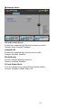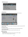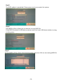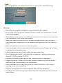
1
UserManual Sapphire EDGE VS Series Mini PC -1 1. Product Specifications Item Description AMD® APU Trinity A4 AMD® APU Trinity A8 AMD® RadeonTM HD7400G AMD® RadeonTM HD7600G CPU Graphics Chipset AMD® Hudson‐M3 (A70M) Chip RAM 4GB – DDR3 Storage 2.5'' SATA 320GB / 500GB / 750GB HDD LAN Built‐in Ethernet supporting 10/100/1000 Mbps WIFI / BT Built‐in WIFI supporting IEEE 802.11 b/g/n ; BT 3.0 I/O 1x Mini DisplayPort, 1x HDMI, 1x RJ45, 2x USB 3.0 Ports, 4x USB 2.0 Ports, 1x Audio‐out, 1x MIC‐in, 1x SPDIF‐out Power AC100~240V 50/60Hz, DC19V 3.42A 65W Dimensions 197.5(L) X 182.5(W) X 31.6(H) mm Weight 660g Operating System Pre‐installed with FREE DOS; Supports Win8/Win7/Vista Important information for your safety and comfort Please read these instructions carefully before using the product and save for future reference. Ensure that the Mini‐PC is turned off and disconnected from the mains supply before cleaning Do not use liquid or aerosol cleaners, a damp cloth should suffice Insert the power connector into the Mini PC before plugging the mains cable into the AC power outlet. When you need to disconnect power to the equipment, unplug the power cord from the AC power outlet before removing the power connector from the Mini PC. -2 2. Product Overview Features No. Item Description 1 Power Switch To switch the Mini PC ON or OFF. 2 Front USB3.0 Ports (remove cover) To connect USB devices. 3 SD/MMC Connector To insert SD/MMC memory cards 4 Power Indicator light and HDD / Wi‐Fi Activity Indicator The light will glow (white) when the power is on and will flash when the hard disk (orange) / Wi‐Fi (green) is in use 5 Mini Display port To connect display devices 6 HDMI port To connect display devices 7 Rear USB 2.0 Ports To connect USB devices 8 LAN Port To connect to an Ethernet LAN 9 DC Input To connect the power supply 10 Audio out jack To connect headphones or speakers 11 Microphone in jack To connect a microphone or other audio source 12 Optical S/PDIF To connect digital audio devices -3 3. Mini PC Setup and Connections To attach the desktop stand Align stand with the base of the Mini PC and fix with screw provided. To connect to a display Connect a display device to the mini display connector located at the rear of the unit. To connect to an HDMI display / TV Connect the display device to the HDMI connector located at the rear of the unit. To connect to a DVI display (1). Connect the HDMI to DVI adapter included with the Mini PC to the HDMI port located at the rear of the unit. (2). Connect the DVI monitor to the female DVI port on the adapter. To connect USB devices Connect USB devices to the USB ports located both at the rear of the unit and under the cover at the front of the unit. -4 To connect to a network Connect the Ethernet cable from your network switch / router to the RJ45 LAN connector located at the back of the unit. To connect the power adapter Connect the power connector from the supplied power supply to the DC – In connector located at the rear of the unit BEFORE attaching the mains power cable to an AC outlet. To connect speakers or headphones Connect the 3.5mm audio cable to the Audio Out jack located at the rear of the unit. To connect a microphone or other audio source Connect the 3.5mm audio cable to the Line In jack located at the rear of the unit. To connect digital speakers or other digital audio devices Connect the S/PDIF cable to the S/PDIF jack located at the rear of the unit. To read media files from an SD/MMC memory card Insert the SD/MMC card into the SD/MMC Connector. -5 Note1: This Mini PC provides one standard RJ‐45 jack for connecting to a Local Area Network (LAN). Two LEDs are built into the RJ‐45 LAN connector. These LEDs indicate the status of the LAN. LED LED Color LED state Indicates A Note2: B Yellow Off LAN link is not established On LAN link is established Blinking LAN activity is occurring N/A Off 10 Mb/s data rate Green On 100 Mb/s data rate Orange On 1000 Mb/s data rate The system provides a Clear CMOS function, which may be helpful once the system is not working normally as usual and can’t be fixed by even rebooting the system. You can use a small object such as a paperclip pushing into the hole and pressing the button hidden inside for at least five seconds. Once the system state is cleared via above operations, you need to set up the correct system state by loading BIOS default. Another use of this button is when BIOS is updated, you need to press this button to clear original settings and then load BIOS default to complete the BIOS update procedure. Clear CMOS -6 4. Mainboard Layout The following figure shows the location of components on the mainboard. Cooler Hard Drive Memory Module Note: Picture is for reference only, actual board may be slightly different. -7 5. Configuring the BIOS This chapter provides information on the BIOS Setup program and allows you to configure the system for optimum use. 5‐1 Select Boot Device Select Boot Device Menu allows you to set the first boot device without entering BIOS Setup. During Power On Self Test (POST), you can press the <F7> key to enter select boot device menu. The system will directly boot from the device configured in Boot Menu. Please Select boot device: P1: DVDRW STA 24X24X12X P0: WDC WD3200AAKS‐00VV3A0 Enter Setup and to move selection ENTER to select boot device ESC to boot using defaults 5‐2 Enter BIOS Setup The BIOS is the communication bridge between hardware and software. Correctly setting the BIOS parameters is critical to maintaining optimal system performance. Use the following procedure to change BIOS settings. 1. Power on the computer. 2. Press the Del key when the following message briefly shows upon the bottom of the display during Power On Self Test (POST). Press F1 to continue, DEL to enter Setup. Pressing Del takes you to the BIOS Aptio Setup Utility. Note1: It is strongly recommended that you do not change the default BIOS settings. Changing some settings could damage your computer. Note2: The BIOS options in this manual are for reference only. BIOS screens in manuals are usually the first BIOS version when the board is released and may be different from your purchased motherboard. Users are welcome to download the latest BIOS version from our official website. (www.sapphiretech.com) -8 Control Keys Please check the following table for the function description of each Control key. You can also use the mouse to click your required item. Control Key(s) Function Description / Moves cursor left or right to select Screens / Moves cursor up or down to select items + / ‐ To change option for the selected items <Enter> To bring up the selected screen <F1> To display the General Help Screen <F2> To load previous values for all the settings <F3> To load optimal default values for all the settings <F4> To save changes and exit the SETUP UTILITY <ESC> To jump to the Exit Screen or exit the current screen -9 5‐3 Main Menu When entering the Aptio Setup Utility, the main menu screen appears. This main menu includes the system overview and displays the basic system configuration, such as BIOS information, memory size and system date/time. BIOS Information BIOS Vendor Core Version Compliancy Project Version Build Date and Time Memory Information Total Memory System Date System Time Access Level 100 2124 4096 1333 Set the Date. Use Tab to switch between Data American Megatrends 4.6.5.3 UEFI 2.3; PI 1.2 FP2M3 0.32 x64 09/26/2012 16:25:43 4096 MB (DDR3) [Fri 09/28/2012] [13:33:51] Administrator 1.152 0.960 1.504 3.200 51 39 BIOS Information This field displays the current BIOS version, build date and ID information etc. Memory Information Able to display current system memory size. System Date Allows you to set the system date. The format is <Day><Month><Date><Year>. [Day] Weekday from Sun. to Sat., this is automatically displayed by BIOS. [Month] The month from 1 to 12. [Date] The date from 1 to 31 can be keyed by numeric function keys. [Year] The year can be adjusted by users. System Time Allows you to set the system time. The time format is <hour>:<minute>:<second>. - 10 5‐4 Advanced Menu The Advanced menu items allow you to change the settings for the CPU, USB and other system devices. Press <Enter> to display the configuration options. RTC Wake Settings ACPI Settings CPU Configuration SATA Configuration USB Configuration H/W Monitor Onboard Device Enable system to wake from S5, S4, S3 using RTC alarm 1.152 0.960 1.504 3.200 100 2124 4096 1333 51 39 RTC Wake Settings Wake systems with Fixed Time Wake system with Dynamic Time Enable or Disable System wake on alarm event. When enabled, System will wake on the hr::min::sec specified. [Disabled] [Disabled] 100 2124 4096 1333 1.152 0.960 1.504 3.200 51 39 Wake system with Fixed Time Enable or disable system wake on alarm event. When enabled, system will wake on the hr:min:sec specified. Options: Enabled, Disabled. Wake system with Dynamic Time Enable or disable system wake on alarm event. When enabled, system will wake on the S5, S4, S3 time + Increase minutes(s). Options: Enabled, Disabled. - 11 ACPI Settings ACPI Settings Enable Hibernation ACPI Sleep State EuP Function Restore AC Power Loss [Enabled] [S3 only (Suspend to RAM)] [Disabled] [Power Off] 100 2124 4096 1333 Enables or Disables system ability to Hibernate (OS/S4 Sleep Sate). This option may be not effective with some OS. 1.152 0.960 1.504 3.200 51 39 Enable Hibernation Enables system ability to Hibernate (OS/S4 Sleep Sate). This option may be not effective with some OS. Options: Enabled, Disabled. ACPI Sleep State Selects the power saving modes for ACPI function. Options: Suspend Disabled, S3 only (Suspend to RAM). EuP Function Enables the EuP (Energy Using Products) function, allows BIOS to switch off some power at S5 state to get system ready for the EuP requirement to reduce power consumption. Options: Enabled, Disabled. Restore on AC Power Loss Enables your computer to automatically restart or return to its last operating status after power returns from a power failure. Options: Power off, Power on, Last State. - 12 CPU Configuration CPU Configuration Module Version: 4.6.5.1 TrinityPI 017 AGESA Version: 1.0.0.7 AMD Cool’n’ Quiet PSTATE Adjustment PPC Adjustment NX Mode SVM Mode AMD Core Performance Boost C6 Mode CPU Information 100 2124 4096 1333 Enable/disable the generation of ACPI_PPC, _PPS, and _PCT objects. [Enabled] [PState 0] [PState 0] [Enabled] [Enabled] [Auto] [Enabled] 1.152 0.960 1.504 3.200 51 39 AMD Cool’n’ Quiet Cool'n'Quiet is a CPU speed throttling and power saving technology by AMD. Options: Enabled, Disabled. PSTATE Adjustment Allows you to adjust startup P‐state level. Options: PState 0, PState 1, PState 2, PState 3, PState 4, PState 5, PState 6, PState 7. PPC Adjustment Allows you to adjust PPC object. Options: PState 0, PState 1, PState 2, PState 3, PState 4. NX Mode Enable or disable No‐execute page protection function. Options: Enabled, Disabled. SVM Mode Enables the CPU SVM( Secure Virtual Machine) function. Options: Enabled, Disabled. AMD Core Performance Boost Allows you to disable AMD Core Performance Boost. Options: Auto, Disabled. C6 Mode Allows you to select C6 State for processor. Options: Enabled, Disabled. - 13 CPU Information Displays the CPU related information. Socket0: AMD A8‐4555M APU with Radeon(tm) HD Graphics Quad Core Running @ 1634 MHz 375 mV Max Speed:1600 MHZ Intended Speed:1600 MHz Min Speed: 900MHZ Microcode Patch Level: 6001116 ‐‐‐‐‐‐‐‐‐‐‐‐‐‐ Cache Per Core ‐‐‐‐‐‐‐‐‐‐‐‐‐‐‐‐‐‐‐‐ L1 Instruction Cache: 32 KB/2‐way L1 Data Cache: 16 KB/4‐way L2 Cache: 1024 KB/16‐way No L3 Cache Present SATA Configuration SATA Configuration OnChip SATA Type [AHCI] AHCI Legacy IDE TOSHIBA MK5065... SATA Port0 100 2124 4096 1333 1.152 0.960 1.504 3.200 51 39 OnChip SATA Type Allows you to set the onboard Serial SATA type. Options: AHCI, Legacy IDE. Legacy IDE Mode: Use the SATA hard disk drivers as Parallel ATA storage devices. AHCI Mode: Use the AHCI (Advanced Host Controller Interface) to enable advanced SATA features for improved performance with NCQ and Hot‐plug features. SATA Port 0 This field shows SATA port connection state. - 14 USB Configuration Enables Legacy USB support. AUTO option disables legacy support if no USB devices are connected. DISABLE option will keep USB devices available only for USB Configuration USB Devices: 1 Keyboard, 1 Mouse Legacy USB Support USB3.0 Support XHCI Hand‐off EHCI Hand‐off [Enabled] [Enabled] [Enabled] [Disabled] USB Hardware delays and time‐outs: USB transfer time‐out [1 sec] Device reset time‐out [10 sec] Device power‐up delay [Auto] Mass Storage Devices: PIONEER DVD‐RW DVR‐XD101.00 100 2124 4096 1333 [Auto] 1.152 0.960 1.504 3.200 51 39 Legacy USB Support Allows you select legacy support for USB devices. Enabled: Enables Legacy USB support. Disabled: Keep USB devices available only for EFI application. Auto: Disables legacy support if no USB devices are connected. USB 3.0 Support Enables USB3.0 (XHCI) controller support. Options: Enabled, Disabled. XHCI Hand‐off This is a workaround for OSs’ without XHCI hand‐off support. The XHCI ownership change should be claimed by XHCI driver. Options: Enabled, Disabled. EHCI Hand‐off This is a workaround for OSs’ without EHCI hand‐off support. The XHCI ownership change should be claimed by EHCI driver. Options: Enabled, Disabled. USB transfer time‐out The time‐out value for control, bulk, and interrupt transfers. Options: 1 sec, 5 sec, 10 sec, 20 sec. Device reset time‐out Sets USB mass storage devices start unit command time‐out. Options: 10 sec, 20 sec, 30 sec, 40 sec. Device power‐up delay Maximum time the device will take before it properly reports itself to the Host controller. ‘Auto’ uses default values; for a Root port it is 100ms, for a Hub port the delay is taken from Hub descriptor. Options: Auto, Manual. - 15 Mass Storage Devices Mass storage device emulation type. 'Auto' enumerates devices according to their media format. Optical drives are emulated as 'CD‐ROM', drives with no media will be emulated according to a drive type. Options: Auto, Floppy, Forced FDD, Hard Disk, CD‐ROM. H/W Monitor PC Health Status CPU Temperature SYSTEM Temperature CPU Fan Speed VCC3V CPU VCore FCH POWER VDIMM CPU NB CPU VDDP VSB3V VBAT : +51 C : +39 C : 4918 RPM : +3.328 V : +1.096 V : +1.096 V : +1.504 V : +0.960 V : +1.208 V : +3.360 V : +3.200 V CPU Fan Mode Setting Temperature Limit of Highest Temperature Limit of Lowest Fan Highest setting Fan Lowest setting [SmartFan] 80 30 100 20 100 2124 4096 1333 1.152 0.960 1.504 3.200 51 39 CPU/ SYSTEM Displays the current CPU and system temperature. CPU Fan Speed Displays the current CPU Fan Speed. VCC3V/ CPU VCore/ FCH POWER/ VDIMM/ CPU NB/ CPU VDDP/ VSB3V/ VBAT The current voltages are automatically detected and displayed by the system. CPU Fan Mode Setting This item controls the speed of the various fans on the motherboard. SmartFan: When you want the speed of the fans automatically controlled based on temperature. Manual By DutyCycle: To set the fan speed to a constant rate, the speed from 0% to 100%. Manual By RPM: This item can manual RPM count setting. - 16 Onboard Device HD Audio Azalia Device Onboard LAN WLAN Module SD Card Reader Mode 100 2124 4096 1333 [Enabled] [Enabled] [Enabled] [ADMA] 1.152 0.960 1.504 3.200 51 39 HD Audio Azalia Device Enables the onboard High Definition Audio controller. Options: Auto, Enabled, Disabled. Onboard LAN Enables the onboard Giga Lan function for LAN. Options: Enabled, Disabled WLAN Module Control onboard Wireless function. Options: Enabled, Disabled. SD Card Reader Mode This item allows you to select SD Card Reader Mode. Options: Disabled, ADMA, DMA, PIO. - 17 5‐5 Chipset Menu The chipset menu items allow you to change the advanced chipset settings. Press <Enter> to display the sub‐menu. South Bridge North Bridge South Bridge Parameters 100 2124 4096 1333 1.152 0.960 1.504 3.200 51 39 South Bridge AMD Reference code Version SB USB Configuration SB SD Configuration 100 2124 4096 1333 Trinity PI 1.0.0.7 Options for SB USB Configuration 1.152 0.960 1.504 3.200 51 39 SB USB Configuration XHCI Controller 0 Enables USB3.0 (XHCI) controller support. Options: Enabled, Disabled. SB SD Configuration SD Trace Length This item allows you to select the SD trace length (inches). Options: Less 6, Between 6 and 11, Greater 11. - 18 SD SPEED This item allows you to select the SD speed. Options: Low, High. SD Bitwidth This item allows you to select the SD bit width. Options: 32Bit, 64Bit. North Bridge GFX Configuration North Bridge Configuration GFX Configuration Memory Information Total Memory: 16384 MB (DDR3) Memory Information DIMM Information 100 2124 4096 1333 1.152 0.960 1.504 3.200 51 39 GFX Configuration Integrated Graphics This item allows you to control Integrated Graphics controller. Options: Auto, Force. UMA Frame buffer Size This item will only appear when “Integrated Graphics” item is set to “Force” option. It controls the amount of system memory that is allocated to the integrated graphics processor. Options: 32M, 64M, 128M, 256M, 512M. Memory Configuration Memory Clock This item allows you to select different memory clock. Options: Auto, 800MHz, 1066MHz, 1333MHz. - 19 DIMM Information This filed displays the related memory information. DIMM Information Starting Address: 0 KB Ending Address: 4194303 KB Dimm0: size=2048 MB, Speed=667 MHz Dimm1: size=2048 MB, Speed=667 MHz 5‐6 Boot Menu The Boot menu is used to configure the boot settings and the boot priority. Boot Configuration Bootup NumLock State Boot Option Priorities Boot Option #1 Hard Drive BBS Priorities CSM Parameters Select the keyboard NumLock state [On] [P0: TOSHIBA MK5065…] 100 2124 4096 1333 1.152 0.960 1.504 3.200 51 39 Bootup NumLock State This item allows you to selects the state of the keyboard’s numlock function after POST. Options: On, Off. Boot Option Priorities These options are used to form the boot order and are dynamically generated. Hard Drive BBS Priorities Allows configure the boot order for a specific Hard Drive device class. CSM Parameters Boot option filter This option controls what devices system can boot to UEFI or Legacy. Options: UEFI and Legacy, Legacy only, UEFI only. - 20 Launch PXE OpROM policy This option controls the execution of UEFI and Legacy PXE OpROM. Options: Do not launch, Legacy only, UEFI only. 5‐7 Security Menu The Security menu allows you to change the system security settings. Password Description If ONLY the Administrator’s password is set, then this only limits access to Setup and is only asked for when entering Setup. If ONLY the User’s password is set, then this is a power on password and must be entered to boot or enter setup. In Setup the user will have Administrator rights. The password must be in the following range: Minimum length 3 Maximum length 20 Set setup Administrator Password. Administrator Password User Password 100 2124 4096 1333 1.152 0.960 1.504 3.200 51 39 Administrator Password If ONLY the Administrator’s password is set, then this only limits access to Setup and is only asked for when entering Setup. The password must be 3 to 20 characters long. User Password If ONLY the User’s password is set, then this is a power on password and must be entered to boot or enter setup. In Setup the user will have Administrator rights. The password must be 3 to 20 characters long. - 21 5‐8 Save & Exit Menu The Exit menu allows you to load the optimal default values for BIOS, and save or discard your changes to the BIOS items. Reset the system after saving the changes. Save Changes and Reset Discard Changes and Reset Restore Defaults Save as User Defaults Restore User Defaults Boot Override P0: TOSHIBA MK5065GSX ‐‐‐‐‐‐‐‐‐‐‐‐‐‐‐‐‐‐‐‐‐‐‐‐‐‐‐‐‐‐‐‐‐‐‐‐‐‐‐‐‐‐‐‐‐‐‐‐‐‐‐‐‐‐‐‐‐‐‐‐‐‐‐‐‐‐‐ S_BIOS Flash Utility 100 2124 4096 1333 1.152 0.960 1.504 3.200 51 39 Save Changes and Reset This resets system after saving the changes. Discard Changes and Reset This resets system without saving the changes. Restore Defaults The restore defaults are the factory settings of this motherboard. Save as User Defaults This is used to save all current settings as user default. The current setup state can later be restored using Restore User Defaults. Restore User Defaults This is used to restore all tokens to settings previously stored by Save as User Defaults. Boot Override This group of functions includes a list, each of them corresponding to one device within the boot order. Select a drive to immediately boot that device regardless of the current boot order. S_BIOS Flash Utility This utility allows you to update the system BIOS in embedded BIOS. Refer to the following steps for S_BIOS Flash. - 22 Step1: Enter BIOS setup screen, select “S_BIOS Flash Utility” item from “Exit” tab. Step2: The S‐BIOS flash utility allows you to: Update BIOS form Drive (please refer to setp3) Save BIOS to Drive (please refer to setp6) Step3: To Update BIOS form Drive, select the BIOS update file and press <OK> to start update. If the BIOS file stored in USB device, please must first insert USB device before turning on the system and make sure the BIOS update file matches your mainboard model. Step4: The update BIOS processing screen appears. - 23 Step5: The BIOS update is completed. Please press any key to restart the system. Step6: Save BIOS to Drive, allows you to save the current BIOS file. If the BIOS file stored in USB device, please must first insert USB device before turning on the system. Step7: To Save BIOS to Drive, Select the stored location and press <OK> to start saving BIOS file. - 24 Step8: After saving BIOS file is completed. Select <Esc> to return “Exit” tab of BIOS setup. Warnings Do not use this product near water or a heat source such as a radiator. Do not place this product on an unstable stand or surface. If the product falls, it could be seriously damaged. The ventilator on the enclosure is used for air convection and to prevent the equipment from overheating. Do not cover the ventilator Never push objects of any kind into this product through cabinet slots as they may touch dangerous voltage points or short‐out parts that could result in a fire or electric shock. Never spill liquid of any kind onto or into the product. To avoid damage of internal components and to prevent battery leakage, do not place the product on a vibrating surface. Keep this equipment away from humidity and high temperature Do not operate the product in a location that is subject to an ambient temperature above 35oC (95oF) or below 0oC (32oF). Avoid using a cleaner containing alcohol or acetone to clean the equipment. Danger of explosion if battery is incorrectly replaced. Replace only with the same or equivalent type recommended by the manufacturer. Route the power cord in a way that people are unlikely to step on it. Do not place anything on top of the power cord. Keep any strong magnetic or electrical objects away from the equipment. Your device and its accessories may contain small parts. Keep them out of the reach of small children. - 25 REACH Complying with the REACH (Registration, Evaluation, Authorization, and Restriction of Chemicals) regulatory framework. RoHS Complying with the RoHS (Restriction of Hazardous Substances) regulatory framework. Lithium‐Ion Battery Warning Danger of explosion if battery is incorrectly replaced. Replace only with the same or equivalent type recommended by the manufacturer. Dispose of used batteries according to the manufacturer’s instructions. CE Mark Warning This is a Class B product, in a domestic environment, this product may cause radio interference, in which case the user may be required to take adequate measures. CE marking for devices without wireless LAN/Bluetooth The shipped version of this device complies with the requirements of the EEC directives 2004/108/EC “Electromagnetic compatibility” and 2006/95/EC “Low voltage directive”. R&TTE Directive 1999/5/EC as attested by conformity with the following harmonized standard: •Article Safety •EN60950 •Article EMC •EN301 489‐1/‐17 •Article Spectrum Usages •EN300 328 WEEE Statement Under the European Union (“EU”) Directive on Waste Electrical and Electronic Equipment, Directive 2002/96/EC, effective from August 13, 2005, states products of “electrical and electronic equipment” no longer may be discarded as municipal waste. Please refer to your original point of purchase for instruction on the correct procedure of discarding as municipal waste. It is the sole responsibility/obligation of the local authorized reseller/distributor of such covered electronic equipment to take back such products at the end of their useful life. For better environmental protection, waste batteries should be collected separately for recycling or special disposal. - 26 FCC Statement This device complies with Part 15 of the FCC Rules. Operation is subject to the following two conditions: (1) This device may not cause harmful interference, and (2) This device must accept any interference received, including interference that may cause undesired operation. Note: The manufacturer is not responsible for ANY interference, for example RADIO or TV interference, caused by unauthorized modifications to this equipment. Such modifications could void the user’s authority to operate the equipment. - 27