1
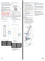
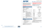
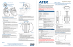
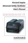
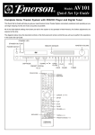
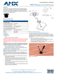
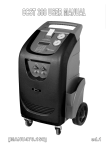
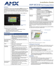
Installation Guide
5) Install the System Into The Mounting Surface
6) Install the System Into the Mounting Surface
1.
2.
Install the unit into the cutout in the mounting surface.
1.
•
Make sure that all cables from the backside terminations pass through
the cutout.
Terminate the backside connections as required for each cable exiting
the HPX system.
2.
•
For terminations for which the far end of the cable is not accessible
(either because the cable has been run under carpet, in a conduit or
structure, or is otherwise fixed), the cable must be placed through the
cutout in the table prior to installation, as indicated in FIG. 5.
Secure these cables and the power cable to either of the end caps
using the supplied wire ties (FIG. 8).
Overview
Product Specifications
The HPX-600/900/1200 family of HydraPort Connection Ports (FG560-xxcc) are built to accommodate the diverse connection needs of conference
and meeting room visitors.
The HPX-600/900/1200 is designed to be mounted into a horizontal
surface such as a conference room table or lectern in order to provide
connectivity for power, networking, Audio/Video and control.
Open the door and rotate the four mounting screws located inside and
at each end of the HPX base assembly in order to rotate the retaining
tabs out under the mounting surface.
Specific connectivity is accomplished by populating the HPX Base
Assembly with various modules.
Note: Make sure that the retaining tabs are down and folded out of the
way prior to installing the unit in the mounting surface.
3.
HPX-600/900/1200 6, 9 and 12 Module Connection Ports
Continue to tighten the mounting screws until the mounting tabs
contact the backside of the mounting surface to retain the HPX
Assembly (FIG. 6).
Number of Modules
Supported:
Module sizes are provided in "HydraPort units".
Modules range in size from 1/2 to 4 1/2 HydraPort units
• HPX-600 - six (6) single-space modules
• HPX-900 - nine (9) single-space modules
• HPX-1200 - twelve (12) single-space modules
Enclosure
• Black anodized metal frame with matte black plastic end
caps (HPX-600/900/1200-BL - FG560-xx-BL).
• Clear anodized metal frame with matte black plastic end
caps (HPX-600/900/1200-SL - FG560-xx-SL).
• Matte black module face plates on all I/O modules.
Optional Accessories:
Compatible HPX Modules and Panels (see below)
Dimensions (HWD):
FIG. 8 Bottom view with cables exiting and secured
3.
HPX-600/900/1200 Specifications
Secure the cables in at least one additional location after they have
been secured to the system so as to prevent undue stress on the
system if the cables are inadvertently kicked, snagged or pulled.
Note: The socket-outlet (Connection to Mains Power branch circuit) shall
be installed near the equipment and shall be easily accessible.
Max above mounting
surface:
• 0.31" (7mm) with lid open
• 0.13" (3mm) with lid closed
Max below mounting
surface:
6.94" (175 mm)
Mounting surface
footprint:
• HPX-600 - 8.19" x 5.44" (208mm x 138mm)
• HPX-900 - 11.16" x 5.44" (283mm x 138mm)
• HPX-1200 - 14.09" x 5.44" (358mm x 138mm)
Min. mounting
surface thickness:
• Min: 0.75" (19mm)
• Max: 2.0" (51 mm)
Table Cutout
Dimensions:
• HPX-600 - 7.64" x 4.84" (194mm x 123mm)
• HPX-900 - 10.59" x 4.84" (269mm x 123mm)
• HPX-1200 - 13.54" x 4.84" (344mm x 123mm)
Additional Documentation
For more detailed installation instructions with additional drawings, please
refer to the HPX-600/900/1200 Installation Guide, available to view or
download from www.amx.com.
Weight:
Base Assembly only:
• HPX-600 - 1.8lbs (0.82Kg)
• HPX-900 - 2.4lbs (1.1Kg)
• HPX-1200 - 2.8lbs (1.3Kg)
Typical Installation:
• HPX-600 = 2.6lbs (1.2Kg)
• HPX-900 = 3.3lbs (1.5Kg)
• HPX-1200 = 4lbs (1.8Kg)
Certifications:
UL 962A
Compatible HPX Modules and Panels
FIG. 1 HPX-600/900/1200 Hydraport Base Assembly
AMX offers 6 versions of the HPX-600/900/1200 Hydraport Base
Assemblies with a variety of compatible modules:
FIG. 6 Mounting Screws & Mounting Tabs
HPX-600/900/1200 Hydraport Base Assemblies
Note: For surfaces less than ¾" (19mm) thick, use the supplied plastic
spacers by fixing them to each end of the cutout using the supplied double
sided tape (FIG. 7).
FIG. 7 Optional spacer and mounting tabs deployed
93-0560-01
Single HDMI Module with Integrated Cable
HPX-AV101-DVI+A
FG552-22
DVI with Stereo Module with Integrated Cables
Single DVI Module with Integrated Cable
HPX-AV101-RGB+A FG552-21
RGB with Stereo Module with Integrated Cables
Hydraport Base Assembly, 6M Capacity,
Black Trim
HPX-600-SL
FG560-01-SL
Hydraport Base Assembly, 6M Capacity,
Silver Trim
HPX-C5400-VGA+A FG552-51-BL-K RGBHV with Stereo UPX Cat5 Kit with HPX
Carrier Module
HPX-900-BL
FG560-02-BL
Hydraport Base Assembly, 9M Capacity,
Black Trim
HPX-C5400-CN+A
FG552-52-BL-K Component with Stereo UPX Cat5 Kit with HPX
Carrier Module
HPX-900-SL
FG560-02-SL
Hydraport Base Assembly, 9M Capacity,
Silver Trim
HPX-N100-RJ45
FG553-01
Single RJ-45 Module
HPX-N102-RJ45
FG553-02
Dual RJ-45 Module
HPX-N100-USB
FG553-11
Single USB Module
HPX-CPT200-W
FG562-41
HydraPort Cable Pass-Thru Module
HPX-U200-MOD
FG554-81
Modero Connection Module
HPX-P200-PC-US
FG561-01
Power Outlet (US) Module
HPX-P250-PC-UK
FG561-11
Power Outlet (UK) Module
HPX-P200-PC-EU
FG561-21
Power Outlet (EU) Module
HPX-P200-PC-AU
FG561-31
Power Outlet (AU) Module with Cord
HPX-P250-PC-IN
FG561-41
Power Outlet (IN) Module
HPX-B050
FG558-01
1/2 M Blank Panel
HPX-B100
FG558-02
1 M Blank Panel
HPX-B200
FG558-03
2 M Blank Panel
HPX-B050-L
FG558-11
1/2 M Custom Label Panel
HPX-B100-L
FG558-12
1 M Custom Label Panel
FG560-03-BL
FG560-03-SL
Hydraport Base Assembly, 12M Capacity,
Black Trim
Hydraport Base Assembly, 12M Capacity,
Silver Trim
ATTENTION: Only a professional, AMX-qualified installer should
perform this installation. Installation must conform to all local codes.
This product may not be installed by the end-user.
4/12
©2012 AMX. All rights reserved. AMX and the AMX logo are registered trademarks of AMX.
AMX reserves the right to alter specifications without notice at any time.
3000 RESEARCH DRIVE, RICHARDSON, TX 75082 • 800.222.0193 • fax 469.624.7153 • technical support 800.932.6993 • www.amx.com
FG552-24
HPX-AV101-DVI
FG560-01-BL
HPX-1200-SL
For full warranty information, refer to the AMX Instruction Manual(s) associated with your Product(s).
HPX-AV101-HDMI
HPX-600-BL
HPX-1200-BL
page 4 of 4
HPX-600/900/1200 Hydraport Base Assemblies are compatible with the
following HPX Modules and Panels:
HPX-C5400-CS+A
FG552-50-BL-K Composite with Stereo UPX Cat5 Kit with HPX
Carrier Module
REV: B
page 1 of 4
Installation of the HPX Base Assembly
Note that very little clearance exists between the HPX Base Assembly and
the hole cutout in the mounting surface.
FIG. 3 indicates the dimensions above the table:
The following sections describe the preparation, installation and setup of
the HPX-600/900/1200 Hydraport Base Assembly. A typical installation will
include several various HPX modules (see Compatible HPX Modules and
Panels above).
Each HPX module has specific instructions for terminating their
connections. Refer to each HPX Module’s Installation Guide during the
installation of the Hydraport system.
Note: Read these instructions in their entirety before beginning the
installation. The installation requires specific steps to be performed
in specific order.
CAUTION: This installation requires specific woodworking skills. This
installation should be performed by an experienced person,
comfortable with these types of woodworking operations. Improper
installation may result in damage to the mounting surface. AMX is not
responsible for damage caused by improper installation.
1) Select a Suitable Location for the HPX Base Assembly
The following figures indicate the space requirements for installing the HPX
Base Assembly:
FIG. 2 indicates the dimensions above the table:
FIG. 3 Dimensions of the HPX Base Assembly (below the table)
•
The Hydraport system requires a mounting surface from 0.5” (13mm)
to 2” (51mm) thick.
•
The Hydraport system requires at least 6 15/16" (175 mm) below the
mounting surface.
Note: Care should also be taken to ensure that the Hydraport system does
not interfere with the normal use of the work space. For example, on a table
or work surface, ensure that the system does not interfere with the user's
legs when they are seated at the table.
2) Cut the Hole In the Mounting Surface
FIG. 4 provides the Hole cutout dimensions for the HPX Base Assembly:
4) Insert the HPX Modules
•
Take care to align the cutout carefully with the edges or other
appropriate features in the table or mounting surface.
Note the orientation of each HPX Module - a small tab exists on one side of
the faceplate of each module. Ensure all tabs are facing the same direction
(see FIG. 5).
•
If the cutout is misaligned, the installed unit will be misaligned.
1.
•
Take care to ensure that the top surface of the mounting surface is not
damaged beyond the width of the trim bezel as the cutout is made.
Remove one end cap of the HPX Base Assembly by removing the six
sheet metal screws and one pivot screw and pivot pawl assembly.
2.
•
Use an appropriate drill and drill bit to make a starting hole within the
boundary of the cutout. Use an appropriate saw, such as a jigsaw to
finish the cutout.
Slide the pre-terminate modules one at a time into the HPX Base
Assembly.
3.
Rout the cables from each module out the bottom of the HPX Base
Assembly.
•
Make sure cutting tool used is appropriate for the material to be cut
and will not tear or chip the top surface.
4.
Use cable ties and one or more of the sliding clips to secure the
cables as needed to the HPX Base Assembly.
•
Note that the process of making the cutout will create substantial dust
and prepare the environment appropriately.
5.
Reinstall the end cap of the HPX Base Assembly by installing the six
sheet metal screws and one pivot screw and pivot pawl assembly.
3) Prepare the Terminations
Some modules that are included in the final system require some type of
backside termination.
Note: Do not over-tighten the pivot pawl screw (i.e., do not use a highpowered drill to tighten this screw).
Note: Refer to the installation guide for each module to determine the
required backside termination.
•
The backside termination for each module can and should be
completed before the module is installed into HPX Base Assembly.
•
For terminations for which the far end of the cable is not accessible
(either because the cable has been run under carpet, in a conduit or
structure, or is otherwise fixed), the cable must be placed through the
cutout in the table prior to installation, as indicated in FIG. 5.
HPX Base Assembly
See table below for the
length of “B” for each
HPX model
See table below for the
length of “A” for each
HPX model
Interlocking tab
Cables
FIG. 2 Dimensions of the HPX Base Assembly (above the table)
Model
Length of “B”
HPX-1200 (Holds up to 12 HPX Modules) 14.09” (358 mm)
HPX-900 (Holds up to 9 HPX Modules)
11.14” (283 mm)
HPX-600 (Holds up to 6 HPX Modules)
8.19” (208 mm)
page 2 of 4
End Cap
FIG. 4 HPX Base Assembly - Hole cutout dimensions
Model
Length of “A”
Mounting Surface
HPX-1200 (Holds up to 12 HPX Modules) 13.54 (344 mm)
HPX-900 (Holds up to 9 HPX Modules)
10.59 (269 mm)
HPX-600 (Holds up to 6 HPX Modules)
7.64 (194 mm)
1.
Carefully measure the tabletop or other mounting surface to locate the
desired position of the HPX Base Assembly.
2.
Use the cutout template supplied with the HPX Base Assembly to
mark the edges of the cutout.
FIG. 5 Inserting the Modules into the Assembly
page 3 of 4