1
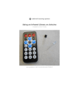
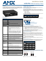
Installation Guide
AXB-IRS4 IR/Serial Interface, 4 Ports
Overview
Configuration and Installation
The AXB-IRS4 (FG5914) operates as an AxLink bus device or as an independent RS-232to-IR interface. The four IR ports can be set up for IR or wired serial operation. Any two ports
can send commands at the same time; internal firmware stacks any remaining IR pulses and
executes them in sequence. Each unit emulates four AxLink devices.
Setting the DIP Switches
Note: Use the DIPSwitch 2.0 application available for free download from AMX to quickly
figure out DIP Switch settings for all types of DIP Switches.
Setting the DEVICE DIP Switch
Set the device number on DEVICE DIP switch, located on the front of the AXB-IRS4. The
device can be 1 of the 255 devices in an Axcess control system. The device number must
match the device assignment in the Axcess program. Device numbers are assigned into the
following three segments:
• Cards 1 through 95
• Boxes 96 through 127
• Panels 128 through 255
Set the device number by setting the device DIP switches. The device number is the total of
all of the switches in the ON position, and take effect by cycling the power.
DEVICE DIP Switch Settings
FIG. 1 AXB-IRS4
AXB-IRS4 Specifications
Control
Controls up to four IR or serial devices
Memory
28K bytes (total); stores up to 200 control commands in each port.
Power requirement
12 VDC
Power consumption
125 mA
Supported baud rates
300, 600, 1,200, 2,400, 4,800, 9,600, 19,200
Front Panel Components
The AxLink LED blinks when there is AxLink or RS-232
communication activity or a memory error. If an AMX system
controls the AXB-IRS4, the green AxLink LED indicates the
following power and data activity, or memory errors:
• One blink per second: Power is active and the AxLink is
functional.
• Full on: Power is active and AxLink communication is not
functional.
• Fast blink: There is a memory error. A memory error can be
caused by a power-deficient battery. Follow the instructions
under Replacing the Lithium Battery section. If the error
continues, contact AMX technical support for assistance.
• If a PC system controls the AXB-IRS4, the green AxLink LED
blinks when RS-232 data is received or transmitted.
DEVICE
DIP switch
8-position DIP switch that sets the AXB-IRS4's device number so
that the Central Controller sends the proper control commands to
the correct device. See Setting the Device DIP Switch for details.
CARRIER/BAUD
DIP switch
8-position DIP switch that sets the carrier/No Carrier (NC) option
on the AXB-IRS4 ports, and the data transmission speed.
See Setting the Carrier/BAUD DIP switch for details.
IR/Serial LEDs
(1-4)
The red IR/SERIAL LEDs blink when the AXB-IRS4 transmits IR
or serial data on ports 1 through 4.
Rear Panel Components
4 IR/Serial
connectors
2-pin captive wire connector for each IR/serial port.
AxLink/RS232
connector
4-pin captive wire connector that supports AxLink or RS-232 data
communications.
• If you have an AMX system, use an AxLink cable to connect to
the control system.
• If you have a PC, use a DB-9 or DB-25 RS-232 cable to connect
to the PC. See Wiring the AXB-IRS4 for details.
PWR connector
1
2
3
4
5
6
7
8
Value
1
2
4
8
16
32
64
128
Setting the Carrier/BAUD DIP Switch
Specifications
AxLink LED
Position
2-pin captive wire connector connects an external 12 VDC power
supply to the AXB-IRS4. An external power supply should be used
when the distance between the AXB-IRS4 and control system
exceeds the wiring guidelines described under Wiring Guidelines.
The CARRIER/BAUD DIP switch sets the carrier signals and baud rates for the AXB-IRS4.
FIG. 2 shows the DIP switch positions.
1
2 3
4 5
6 7
8
NC
Baud rate settings
RS232/PCTouch mode select
Carrier signal enable/disable
FIG. 2 CARRIER/BAUD DIP switch
Positions 1-4: Carrier Signal Enable/Disable
DIP Switch positions 1-4 on the CARRIER/BAUD DIP switch determine wether the
AXB-IRS4 transmits carrier signals along with the IR equipment codes.
• If DIP switch positions 1 through 4 are set to the up position, the carrier signal is
enabled and the AXB-IRS4 transmits IR equipment codes at device-specific signal frequencies.
• If DIP switch positions 1 through 4 are set to NC (down), the carrier signal is disabled
and the IR equipment codes transmit without the carrier signal.
Set the DIP switch positions 1 through 4 when you determine the port assignments and
signal requirements for the IR and serial devices in your system.
Position 5: RS-232/PCTouch Mode
DIP switch position 5 on the CARRIER/BAUD DIP switch sets either RS-232 or PCTouch
mode.
If you enable PCTouch mode, the AXB-IRS4 will only respond to PCTouch (PCCOM)
command protocol. If you enable RS-232 mode, the AXB-IRS4 will respond to the standard
AXB-IRS4 control protocol, PCCOM control protocol, and SX-DCU+ control protocol.
You can also use RS-232 mode to download codes to the AXB-IRS4 with the IRLIB software
program.
• Position 5 (up): RS-232 mode enabled.
• Position 5 (down): PCTouch mode enabled.
Note: Refer to the PCTouch/ PCDesign Instruction Manual for detailed PCTouch program
information.
Positions 6-8: Baud Rate Setting
DIP switch positions 6-8 on the CARRIER/BAUD DIP switch sets the baud rate for RS232
communications. Communication settings are 1 stop bit, 8 data bits, and no parity. The
following table shows the baud rate settings on the CARRIER/BAUD DIP switch.
RS-232 Baud Rate Settings
Baud
Rates
6
DIP Switches
7
8
300
Off
Off
Off
Off
600
On
Off
1,200
Off
On
Off
2,400
On
On
Off
4,800
Off
Off
On
9,600
On
Off
On
19,200
Off
On
On
Battery
Lithium battery backup for stored control commands
Setting Internal Jumpers E1 and E2 for Communication Mode
Enclosure type
Metal with black textured finish
Internal jumpers are located on the circuit card inside the AXB-IRS4 enclosure. You will need
a Phillips-head screwdriver to open the enclosure..
Weight
1.12 lbs (508 grams)
Dimensions
1.51" x 5.55" x 5.45" (38.4mm x 141.0mm x 138.4mm)
Mounting options
• Flat surface
• Rack mount, with optional AC-RK Rack Kit
AXM
AXP
AXM
AXP
AxLink
RX
TX
RS232
RX
TX
FIG. 3 Internal jumpers E1 and E2: Communication Settings
Note: Static electricity can damage electronic circuitry. Before removing the AXB-IRS4 circuit
card from the enclosure, discharge any accumulated static electricity from your body and the
screwdriver by touching a properly grounded metal object.
Removing The Circuit Card
1.
2.
3.
4.
Discharge the static electricity from your body and the screwdriver.
Unplug all connectors from the rear panel of the AXB-IRS4.
Remove the two Phillips-head screws on the front or rear panel.
Remove the front or rear panel, and slide the circuit card out of the enclosure.
Using AxLink For Data and a 12 VDC Power Supply
Connect the Central Controller's AxLink connector to the AxLink/RS-232 connector, on the
rear panel of the AXB-IRS4, and the optional 12 VDC power supply, as shown in FIG. 6.
12 VDC PWR connector
on AXB-IRS4
AxLink Communication
1.
2.
Place the 2-pin jumper on the AXM/RX (E1) connector pins 1 and 2.
Place the 2-pin jumper on the AXP/TX (E2) connector pins 1 and 2.
AxLink/RS232 connector
on AXB-IRS4
RS232 Communication
1.
Place the 2-pin jumper on the AXM/RX (E1) connector pins 2 and 3.
2.
Place the 2-pin jumper on the AXP/TX (E2) connector pins 2 and 3.
3.
Set all the DEVICE DIP switch positions to OFF (up).
One the jumpers are set, replace the card in the enclosure. Replace the front or rear panel,
refasten the two Phillips-head screws, and plug in all connectors.
Wiring the AXB-IRS4
4
1
AXP / TX
PWR
AXM / RX
GND
GND
GND
2
IR
SER
GND
GND
3
IR
SER
GND
GND
IR
SER
GND
GND
IR
SER
The serial, IR, AxLink, and power supply connectors are located on the rear panel of the
AXB-IRS4 as shown in FIG. 4. The AxLink connector can also be used for RS-232
communications.
AXlink / RS-232
12VDC
PWR
Wiring Guidelines
The AXB-IRS4 requires 12 VDC power to operate properly. The power can be supplied by
the AMX system's AxLink cable or with an optional 12 VDC power supply. The maximum
wiring distance between the control system and AXB-IRS4 is determined by power
consumption, supplied voltage, and the wire gauge used for the cable.
The following table lists wire sizes and the maximum lengths allowable between the AXBIRS4 and control system. The maximum wiring lengths for using AxLink power are based on
a minimum of 13.5 volts available at the control system's power supply.
Wiring Guidelines at 125 mA
Maximum Wiring Length
938.97 feet (286.19 m)
20 AWG
594.06 feet (181.07 m)
22 AWG
370.37 feet (112.89 m)
24 AWG
233.46 feet (71.16 m)
Using AxLink for Data and Power
Connect the Central Controller's AxLink connector to the AxLink/RS-232 connector, on the
rear panel of the AXB-IRS4, for data and 12 VDC power, as shown in FIG. 5.
AxLink/RS232 connector
on AXB-IRS4
no connection
PWR(+)
PWR
AXP/TX
AXP
AXM/RX
AXM
GND
GND (-)
FIG. 5 AxLink data and power wiring diagram
AXM
GND (-)
GND
Axcess
Control
System
Additional Wiring Options
Refer to the AXB-IRS4 Operation/Reference Guide for additional wiring information,
including details on:
• Using the AxLink-to-DB-9 connector cable for a PC system
• Using the AxLink-to-DB-25 connector cable for a PC system
Connecting an IR Device
IR devices connect to the AXB-IRS4 with an IR device cable. The cables supplied with the
AXB-IRS4 are designed to accommodate the IR devices in your system.
IR cables have a two-pin connector on one end that plugs into the AXB-IRS4, and the other
end has a device-specific interface adapter such as an IR emitter.
Connect IR devices to the AXB-IRS4 as shown in FIG. 7.
IR/Serial connector
on AXB-IRS4
IR
GND
IR emitter
IR device
SER
FIG. 7 IR device wiring diagram
Connecting a Serial Device
Serial devices connect to the AXB-IRS4 with a serial device cable. The cables supplied with
the AXB-IRS4 are designed to accommodate the serial devices in your system. Serial cables
have a two-pin connector on one end that plugs into the AXB-IRS4, and the other end has a
device-specific interface adapter such as a control plug.
Connect serial devices to the AXB-IRS4 as shown in FIG. 8. Each serial device requires a
model-specific cable. Make sure to match each serial device with the appropriate cable.
IR
GND
IR device
SER
Strip 0.25 inch of wire insulation off all wires.
Insert each wire into the appropriate opening on the connector according to the wiring
diagrams and connector types described in this section. Do not tighten the screws
excessively; doing so may strip the threads and damage the connector.
PWR (+)
GND (-)
AXP
AXM/RX
Use the 12 VDC power supply when the distance between the AMX system and AXB-IRS4
exceeds the limits described in the Wiring Guidelines at 125 mA table
Make sure to connect only the GND wire on the AxLink/RS-232 connector when using a 12
VDC power supply. Do not connect the PWR wire to the AxLink connector's PWR opening.
IR/Serial connector
on AXB-IRS4
Preparing/Connecting Captive Wires
12 VDC PWR connector
on AXB-IRS4
PWR
AXP/TX
GND
If the AXB-IRS4 is installed farther away from the control system than recommended in the
Wiring Guidelines table, connect a 12 VDC power supply to the 2-pin 12 VDC PWR
connector on the rear panel.
1.
2.
PWR(+)
GND
Note: Do not connect power to the AXB-IRS4 until the wiring is complete. If you are using
power from AxLink, disconnect the wiring from the Card-Frame before wiring the AXB-IRS4.
If you are using an optional 12 VDC power supply, apply power to the AXB-IRS4 only when
the installation is complete.
18 AWG
12 VDC power supply
FIG. 6 AxLink and optional 12 VDC power supply wiring diagram
FIG. 4 AXB-IRS4 rear panel connectors
Wire Size
PWR (+)
GND (-)
Axcess
Control
System
FIG. 8 Serial device wiring diagram
Replacing the Lithium Batteries
The AXB-IRS4’s lithium batteries have a life of approximately 5 years to protect its memory.
When DC power is on, the batteries are not used. When you install the AXB-IRS4, record the
date the batteries should be replaced.
CAUTION:
• All control commands in memory are lost when the lithium battery is replaced.
• Static electricity can damage electronic circuitry. Before removing the lithium battery
from the enclosure, discharge any accumulated static electricity from your body by
touching a grounded metal object.
Note: There is a danger of explosion if you replace the batteries incorrectly. Replace
batteries with the same or equivalent type recommended by the manufacturer. Dispose of
the used batteries according to the manufacturer’s instructions. Never recharge,
disassemble, or heat batteries above 212°F (100°C). Never solder directly to the batteries or
expose the contents of the batteries to water.
Before removing the lithium batteries, contact your dealer and verify that they have a current
copy of your program to avoid an inadvertent loss of data and prevent an unnecessary
service outage.
You will need a flat-blade tool (non-conducting) that can be slipped under the lithium battery
to pry it up and out of the socket.
1.
Discharge the static electricity from your body.
2.
Unplug the 2-pin power connector and any other connectors.
3.
Remove the 2 screws on the front panel, remove the front panel, and slide the circuit
board out of the enclosure.
4.
Carefully slide each battery out of its socket, and insert the new battery.
5.
Slide the circuit board back into place, replace the front panel and refasten the screws.
6.
Reconnect any connectors that you removed.
Additional Documentation
Refer to the AXB-IRS4 Operation/Reference Guide for programming information.
For full warranty information, refer to the AMX Instruction Manual(s) associated with your Product(s).
5/12
©2012 AMX. All rights reserved. AMX and the AMX logo are registered trademarks of AMX.
AMX reserves the right to alter specifications without notice at any time.
3000 RESEARCH DRIVE, RICHARDSON, TX 75082 • 800.222.0193 • fax 469.624.7153 • technical support 800.932.6993 • www.amx.com
93-5914-01
REV: A