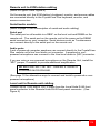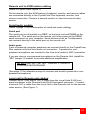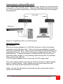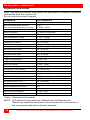
1
CrystalView Plus ENHANCED CAT5 KVM EXTENDER INSTALLATION AND OPERATIONS MANUAL 10707 Stancliff Road Houston, Texas 77099 Phone: (281) 933-7673 Internet: WWW.ROSE.COM LIMITED WARRANTY ® Rose Electronics warrants the CrystalView Plus™ to be in good working order for one year from the date of purchase from Rose Electronics or an authorized dealer. Should this product fail to be in good working order at any time during this one-year warranty period, Rose Electronics will, at its option, repair or replace the Unit as set forth below. Repair parts and replacement units will be either reconditioned or new. All replaced parts become the property of Rose Electronics. This limited warranty does not include service to repair damage to the Unit resulting from accident, disaster, abuse, or unauthorized modification of the Unit, including static discharge and power surges. Limited Warranty service may be obtained by delivering this unit during the one-year warranty period to Rose Electronics or an authorized repair center providing a proof of purchase date. If this Unit is delivered by mail, you agree to insure the Unit or assume the risk of loss or damage in transit, to prepay shipping charges to the warranty service location, and to use the original shipping container or its equivalent. You must call for a return authorization number first. Under no circumstances will a unit be accepted without a return authorization number. Contact an authorized repair center or Rose Electronics for further information. ALL EXPRESS AND IMPLIED WARRANTIES FOR THIS PRODUCT INCLUDING THE WARRANTIES OF MERCHANTABILITY AND FITNESS FOR A PARTICULAR PURPOSE, ARE LIMITED IN DURATION TO A PERIOD OF ONE YEAR FROM THE DATE OF PURCHASE, AND NO WARRANTIES, WHETHER EXPRESS OR IMPLIED, WILL APPLY AFTER THIS PERIOD. SOME STATES DO NOT ALLOW LIMITATIONS ON HOW LONG AN IMPLIED WARRANTY LASTS, SO THE ABOVE LIMITATION MAY NOT APPLY TO YOU. IF THIS PRODUCT IS NOT IN GOOD WORKING ORDER AS WARRANTIED ABOVE, YOUR SOLE REMEDY SHALL BE REPLACEMENT OR REPAIR AS PROVIDED ABOVE. IN NO EVENT WILL ROSE ELECTRONICS BE LIABLE TO YOU FOR ANY DAMAGES INCLUDING ANY LOST PROFITS, LOST SAVINGS OR OTHER INCIDENTAL OR CONSEQUENTIAL DAMAGES ARISING OUT OF THE USE OF OR THE INABILITY TO USE SUCH PRODUCT, EVEN IF ROSE ELECTRONICS OR AN AUTHORIZED DEALER HAS BEEN ADVISED OF THE POSSIBILITY OF SUCH DAMAGES, OR FOR ANY CLAIM BY ANY OTHER PARTY. SOME STATES DO NOT ALLOW THE EXCLUSION OR LIMITATION OF INCIDENTAL OR CONSEQUENTIAL DAMAGES FOR CONSUMER PRODUCTS, SO THE ABOVE MAY NOT APPLY TO YOU. THIS WARRANTY GIVES YOU SPECIFIC LEGAL RIGHTS AND YOU MAY ALSO HAVE OTHER RIGHTS WHICH MAY VARY FROM STATE TO STATE. NOTE: This equipment has been tested and found to comply with the limits for a Class A digital device, pursuant to Part 15 of the FCC Rules. These limits are designed to provide reasonable protection against harmful interference when the equipment is operated in a commercial environment. This equipment generates, uses, and can radiate radio frequency energy and, if not installed and used in accordance with the instruction manual, may cause harmful interference to radio communications. Operation of this equipment in a residential area is likely to cause harmful interference in which case the user will be required to correct the interference at his own expense. IBM, AT, and PS/2 are trademarks of International Business Machines Corp. Microsoft and Microsoft Windows are registered trademarks of Microsoft Corp. Any other trademarks mentioned in this manual are acknowledged to be the property of the trademark owner. Copyright Rose Electronics 2004. All rights reserved. No part of this manual may be reproduced, stored in a retrieval system, or transcribed in any form or any means, electronic or mechanical, including photocopying and recording, without the prior written permission of Rose Electronics. Rose Electronics Part # MAN-CRVP Printed In the United States of America - Revision 1.7 FCC/IC STATEMENTS, EU DECLARATION OF CONFORMITY FEDERAL COMMUNICATIONS COMMISSION AND INDUSTRY CANADA RADIO-FREQUENCY INTERFERENCE STATEMENTS This equipment generates, uses and can radiate radio frequency energy and if not installed and used properly, that is in strict accordance with the manufacturer’s instructions may cause interference to radio communication. It has been tested and found to comply with the limits for a Class A digital device in accordance with the specifications of Part 15 of FCC rules, which are designed to provide reasonable protection against such interference when the equipment is operated in a commercial environment. Operation of this equipment in a residential area is likely to cause interference, in which case the user at his own expense will be required to take whatever measures may be necessary to correct the interference. Changes or modifications not expressly approved by the party responsible for compliance could void the user’s authority to operate the equipment. This digital apparatus does not exceed the Class A limits for radio noise emission from digital apparatus set out in the Radio Interference Regulation of Industry Canada. Le présent appareil numérique n’émet pas de bruits radioélectriques dépassant les limites applicables aux appareils numériques de la classe A prescrites dans le Règlement sur le brouillage radioélectrique publié par Industrie Canada. EUROPEAN UNION DECLARATION OF CONFORMITY ACCORDING TO COUNCIL DIRECTIVE 89/336EEC & 73/23EEC This equipment is in conformity with the protection requirements of the following Council Directives: The Declaration of Conformity is based upon compliance of the product with the following harmonized standards: EN55022: 1998 EN61000-4-5: 1995 EN55024: 1998 EN61000-4-6: 1996 EN61000-4-2: 1995 EN61000-4-11: 1994 EN61000-4-3: 1995 EN60950: 2000 EN61000-4-4: 1995 TABLE OF CONTENTS Contents Disclaimer ...................................................................................................... 1 System introduction ....................................................................................... 1 Features .................................................................................................... 2 Compatibility ............................................................................................. 3 Package contents ..................................................................................... 3 Single video Local models ............................................................................. 4 Single video Remote models ......................................................................... 5 Dual video local models ................................................................................. 6 Dual video remote models ............................................................................. 7 Quad video remote models ............................................................................ 8 Cables ............................................................................................................ 9 Serial cable ............................................................................................. 10 Audio cable ............................................................................................. 10 Installation .................................................................................................... 11 Connecting the cables ............................................................................ 12 Dual Video cabling .................................................................................. 14 Quad Video Remote Unit cabling ........................................................... 16 Keyboard commands .............................................................................. 18 Keyboard command descriptions ........................................................... 19 Local unit Keyboard commands (Dual local model only) ....................... 22 Adjusting the video ................................................................................. 24 Operating instructions- All units ................................................................... 27 Operating instructions – Dual unit ................................................................ 27 KVM Switching ........................................................................................ 27 Private mode (Dual access models only) ............................................... 27 Troubleshooting ........................................................................................... 28 Service Information ...................................................................................... 30 Maintenance and Repair ......................................................................... 30 Technical Support ................................................................................... 30 Safety ........................................................................................................... 31 Figures Figure 1. Single Video (Local models) ........................................................... 4 Figure 2. single Video (Remote models) ....................................................... 5 Figure 3. Dual video (Local models) .............................................................. 6 Figure 4. Dual video (Remote models) .......................................................... 7 Figure 5. Quad video (Remote models) ........................................................ 8 Figure 6. Single video cabling ..................................................................... 12 Figure 7. Dual video cabling ........................................................................ 14 Figure 8. Quad video cabling ....................................................................... 16 Figure 9. CrystalView Plus to a KVM switch................................................ 17 Figure 10. Color skew delay compensation................................................. 24 Figure 11. Video Test Card ......................................................................... 25 Figure 12 HF / LF adjustment guide. ........................................................... 25 Tables Table 1. Keyboard Commands .................................................................... 18 Table 2. Channel select ............................................................................... 19 Table 3. Private mode commands ............................................................... 27 Appendices Appendix A. General specifications ............................................................. 33 Appendix B. Parts and cables ..................................................................... 35 Appendix C. Rack mount instructions .......................................................... 36 Appendix D. Rack mount illustration............................................................ 36 Appendix E. Quick Installation/Setup Guide ................................................ 37 INTRODUCTION Disclaimer While every precaution has been taken in the preparation of this manual, the manufacturer assumes no responsibility for errors or omissions. Neither does the manufacturer assume any liability for damages resulting from the use of the information contained herein. The manufacturer reserves the right to change the specifications, functions, or circuitry of the product without notice. The manufacturer cannot accept liability for damages due to misuse of the product or other circumstances outside the manufacturer’s control. The manufacturer will not be responsible for any loss, damage, or injury arising directly or indirectly from the use of this product. System introduction Thank you for choosing the Rose Electronics CrystalView Plus enhanced KVM station extender. The CrystalView Plus is the result of Rose Electronics commitment to providing state-of-the-art solutions for today’s demanding workplace. The CrystalView Plus has proven to be a valuable investment for any business, big or small, that has a need to access CPUs from Remote locations. The CrystalView Plus is available in several models; single, dual, and quad video models and the PC-Serial/Audio model. The single video model is available in a local and remote access version. The local access version allows an additional KVM station to be connected to the Local Unit. The CrystalView Plus system consists of two Units, a Local Unit and a Remote Unit. The Local Unit connects to your CPU and one to four video sources or a Rose switch. The Remote Unit connects to a keyboard, one to four video monitors and a mouse. The Local and Remote Units are connected together with industry standard CAT-5, CAT-5e, or CAT-6 shielded or unshielded, solid core twisted-pair cable terminated with RJ45 connectors. All models can extend the distance from the CPU up to 1,000 feet. CAT-x cable can be ordered from Rose Electronics in 25-1,000 foot lengths. Using the CrystalView Plus to remotely access your computer has several applications that make it convenient for the users. You can locate your computers in a secure area and access them from other unsecured areas. Computers used in hazardous industrial environments can be accessed remotely, keeping the users safe and unexposed to any hazards. CRYSTALVIEW PLUS INSTALLATION AND OPERATIONS MANUAL 1 Features Available in single, dual, and quad video models Extend a KVM station from a CPU using a single CAT-x cable. (Up to 650 feet at resolutions of 1600 x 1200 @ 60Hz, 1,000 feet for the resolutions of 1280 x 1024 @ 75Hz.) Supports PCs, serial, and full stereo audio Supports PS/2 keyboard/mouse and all PC video formats The CrystalView Plus uses a microprocessor to emulate the keyboard and mouse for plug and play operation. The keyboard and mouse on the Remote Unit do not have to be connected for the PC to boot; only the Local Unit must be connected to the PC Integrated skew compensation adjusts all colors Low frequency (LF) and high frequency (HF) equalization adjustments for optimum video tuning Compatible with Rose Electronics family of KVM switches such as ServeView Pro, UltraView Pro and UltraMatrix Compatible with Windows, Windows NT, OS/2, Unix, Linux and other operating systems Fully automatic KVM sharing on a first-come first-serve basis using the local access model On a local access Unit, computers video is displayed on both KVM stations monitors except in the private mode Local or Remote KVM station can inhibit the other on the local access models Bi-directional serial and full stereo audio options Stereo audio can be transmitted in either direction across the CAT-x link simultaneously Many serial devices like a Touchscreen can plug directly into the Remote Unit (Serial/Audio Model). Status indicator LEDs on each RJ45 connector Surge protection on each RJ45 port All settings and video tuning performed from the remote unit and saved in flash memory Remote unit is flash upgradeable Rack mount kits available in 19”, 23” and 24” sizes 2 CRYSTALVIEW PLUS INSTALLATION AND OPERATIONS MANUAL Compatibility Computers PCs with standard PS/2 keyboards and PS/2 mice Monitors VGA to UXGA HV, Composite, Sync-on-green, Keyboards PS/2 types of keyboard. Mouse PS/2, (2 or 3-button), Wheel mouse Microsoft IntelliMouse Serial Devices (Serial/Audio model only) Touchscreens, Graphic Tablets, Serial printers/plotters, Computer terminals Serial mice, Other standard asynchronous serial devices. Audio Devices (Serial/Audio model only) Compatible sound cards Amplified or non-amplified microphone Amplified computer stereo speakers Other audio devices that transmit/receive signals less than 5 volts peak-to-peak. Package contents The package contents consist of the following: The CrystalView Plus Units as ordered Power adapter for Remote Unit. (Auto-switching transformer) Gender changer (factory installed) Installation and operations manual. CPU, serial, audio and CAT-x cables are usually ordered separately. If the package contents are not correct, contact Rose Electronics or your reseller, so the problem can be quickly resolved. Rose Electronics web site Visit out web site at www.rose.com for additional information on the CrystalView Plus and other products that are designed for data center applications, classroom environments and other applications. About this manual This manual covers the installation and operation of the CrystalView Plus PC and PC-Serial/Audio models. CRYSTALVIEW PLUS INSTALLATION AND OPERATIONS MANUAL 3 MODELS Single video Local models Front view Rear view Rear view with serial/audio Rear view with local access Rear view with local access & serial/audio Figure 1. Single Video (Local models) Connectors: Front RJ45 CATx cable connection (front panel) Rear Local Single HD15M CPU video connection. MiniDin-6 (2) CPU keyboard and mouse connections . Rear Local Single with serial/audio HD15M CPU video connection. MiniDin-6 (2) CPU keyboard and mouse connections DB9F Serial connector Audio (2) 3.5mm stereo connectors Rear Local Dual HD15M CPU video connection. HD15F KVM stations video monitor connection. MiniDin-6 (4) CPU & KVM keyboard and mouse connection Rear Local Dual with serial/audio HD15M CPU video connection. HD15F KVM stations video monitor connection. MiniDin-6 (4) CPU & KVM keyboard and mouse connection DB9F Serial connector Audio (2) 3.5mm stereo connectors 4 CRYSTALVIEW PLUS INSTALLATION AND OPERATIONS MANUAL Single video Remote models Front view Rear view Rear view with serial/audio Figure 2. single Video (Remote models) Connectors: Front RJ45 CATx cable connection (front panel) Rear Remote HD15F MiniDin-6 Power KVM video connection. (2) KVM keyboard and mouse connections 9V power adapter connector Rear remote with serial/audio HD15F KVM video connection MiniDin-6 (2) KVM keyboard and mouse connections DB9M Serial connector Audio (2) 3.5mm stereo connectors Power 9V power adapter connector CRYSTALVIEW PLUS INSTALLATION AND OPERATIONS MANUAL 5 Dual video local models Front view Rear view Rear view with serial/audio Figure 3. Dual video (Local models) Connectors: Front RJ45 (2) CATx cable connection (front panel) Rear Local DB25F Power (2) CPU & second video Optional 5V DC power adapter connector Rear Local with serial/audio DB25F (2) CPU & second video. DB9F Serial connector Audio (2) 3.5mm stereo connectors Power Optional 5V DC power adapter connector 6 CRYSTALVIEW PLUS INSTALLATION AND OPERATIONS MANUAL Dual video remote models Front view Rear view Rear view with serial/audio Figure 4. Dual video (Remote models) Connectors: Front RJ45 (2) CATx cable connection (front panel) Rear remote HD15F HD15F MiniDin-6 Power KVM station video Second video monitor (2) KVM keyboard and mouse connections 9V DC power adapter connector Rear remote with serial/audio HD15F KVM station video HD15F Second video monitor MiniDin-6 (2) KVM keyboard and mouse connections Audio (2) 3.5mm stereo connectors DB9M Serial connector Power 9V DC power adapter connector CRYSTALVIEW PLUS INSTALLATION AND OPERATIONS MANUAL 7 Quad video remote models Front view Rear view Rear view with serial/ audio Figure 5. Quad video (Remote models) Connectors: Front RJ45 (4) CATx cable connection (front panel) Rear remote HD15F MiniDin-6 HD15F HD15F HD15F Power KVM station video (2) KVM keyboard and mouse connections Second video monitor Third video monitor Fourth video monitor 9V DC power adapter connector Rear remote with serial/audio HD15F KVM station video MiniDin-6 (2) KVM keyboard and mouse connections HD15F Second video monitor HD15F Third video monitor HD15F Fourth video monitor Audio (2) 3.5mm stereo connectors DB9M Serial connector Power 9V DC power adapter connector 8 CRYSTALVIEW PLUS INSTALLATION AND OPERATIONS MANUAL CABLES Cables CrystalView Plus Local Unit to CPU cable A CPU adapter cable is used to connect from the Local Unit to a CPUs keyboard, video monitor and mouse ports. The Serial/Audio models use a male-to-male cable configured on both ends with an HD15M VGA connector, two MiniDin-6 connectors for the PS/2 keyboard and mouse, a 3.5mm audio cable, and a DB9MF serial cable. The dual video model uses a DB25M to HD15M cable. The quad video model use a standard HD15M to HD15M video cable for each additional CPU video output. Max Local unit to CPU cable length is 20 feet using standard cabling. Using coax cabling, this distance can be extended, but care should be taken because power for the Local unit is obtained from the connected CPUs keyboard port. Extended distances may require the use of an additional power supply for the local unit. CrystalView Plus Remote Unit to KVM station cable The keyboard, video monitor, and mouse cables on a KVM station can connect directly to the CrystalView Plus Remote unit or the Dual Local Unit connectors if they are HD15M Video connector and PS/2, MiniDin-6 Keyboard and Mouse connectors. Stereo speakers and a microphone can connect directly to the remote unit’s audio ports. The dual and quad video models use a standard HD15M to HD15M video cable for each additional video source. CrystalView Plus to Rose switch cable To connect a Local Unit to a Rose switch such as a ServeView Pro, UltraMatrix or UltraView Pro, use Rose cable part number CAB-CX0606Cnnn. (DB25F to HD15/PS2/PS2) Local Unit to Remote Unit cable The Local Unit is connected to the Remote Unit with up to 1,000 feet of standard CAT-x UTP/STP “solid core” cable terminated with RJ45 connectors. Rose Electronics cable part number CAB-08UTPnnn. The dual and quad video models use two or four CAT-x cables from the local unit to the remote unit. CRYSTALVIEW PLUS INSTALLATION AND OPERATIONS MANUAL 9 Serial cable To connect the Local Unit to the CPUs DB9 serial port, you can use a standard DB9MF serial 1:1 (DTE-DCE) cable. The Remote Units “SERIAL” port is wired as DTE (the same as the CPUs serial port). To connect a serial printer or other DTE devices to the Remote Unit, you will need a Nullmodem (crossover) cable between the Remote Unit and the device. Select Xon/Xoff software flow control on the printer and PC. A serial Touchscreen can be directly connected to the Remote unit’s serial port. Audio cable CrystalView Plus models with the audio option are configured with two 3.5mm stereo audio jacks on both the Local and Remote Unit. Standard 3.5mm stereo audio cables can be used to connect between the Local Units “LINE IN” connector and a sound card’s “LINE OUT” connector. The Remote Units “LINE OUT” connects to a pair of powered computer speakers. If you want to use a microphone on the remote unit, there are two ways to set this up: 1. Method #1 a) Connect the “LINE OUT” connector on the local unit to the “MIC” input on the CPUs sound card b) Connect a microphone to the remote units “LINE IN” connector c) Adjust the sound card to provide an additional +20dB of amplification. 2. Method #2 (use the Remote unit for additional amplification) a) Remove the Remote units power and cover and locate the jumper labeled “MIC” and connect a jumper across the pins b) Replace the Remote units cover and restore power c) Connect a non-powered microphone to the Remote units “LINE IN” connector and the Local units “LINE OUT” to the CPUs sound cards “MIC IN” connector. NOTE: If you are using a powered microphone, connect it directly to the “LINE IN” connector on the remote unit and connect the Local units “LINE OUT” connector to the sound cards “LINE IN” connector (DO NOT INSTALL THE “MIC” JUMPER) The video performance will vary with different cable types. The CrystalView Plus makes it easy to adjust the skew and video compensation with simple keyboard commands. 10 CRYSTALVIEW PLUS INSTALLATION AND OPERATIONS MANUAL INSTALLATION Installation Please refer to the safety section first before proceeding with any installation or configuration of the CrystalView Plus. Installation of the CrystalView Plus consists of three easy steps. 1. Connect the cables to the equipment. 2. Applying power. 3. Adjust the video channels (if needed). More advanced users can refer to Appendix E for a quick installation and video compensation adjustment guide. For systems that only require running Video through the CrystalView Plus with no keyboard or mouse or use extended cable lengths between the local unit and a computer or KVM switch, supplemental power should be supplied to the Local Unit. The Local Unit gets its power from the keyboard port of the CPU. Rose Electronics can supply a power transformer that connects to the Local Unit to provide this power. This power transformer can be ordered from Rose Electronics (P/N TFR-05D400FSUB) When installing the CrystalView Plus, locate the Local unit as close as possible to the CPU. Keep the CPU and KVM cables as short as possible but still give some freedom of movement. Using shorter cables keeps the video noise to a minimum and reduces installation costs. You can mount the CrystalView Plus in a CPU rack with the optional rack mount kit. When mounting in a rack, follow the instructions in Appendix C and Appendix D and assure that the operating temperature of the Local and Remote Units do not exceed the maximum ratings. Provide adequate air circulation to assure that the maximum operating temperature is not exceeded. Wherever the CrystalView Plus Local and Remote Units are located, they should be on a secure surface and free from obstructions and objects that may cause damage to the units. CRYSTALVIEW PLUS INSTALLATION AND OPERATIONS MANUAL 11 Connecting the cables CATx CABLE LOCAL REMOTE CPU CABLE SERIAL/AUDIO KVM STATION SERIAL MIC SPEAKERS Figure 6. Single video cabling Local unit to CPU cabling (Refer to Figure 1 and Figure 6) The keyboard, video, and mouse ports on the CPU are connected to the keyboard, video, and mouse ports on the CrystalView plus using an appropriate CPU adapter cable. Serial/audio models (Refer to page 10 for a description of serial and audio cabling) For the serial/audio models, connect the serial DB9M port on the CPU to the DB9F serial connector on the CrystalView Plus using a DB9F to DB9M serial cable. The line out of the CPU’s sound card connects to the Line in port on the CrystalView Plus. The line in connects to the CrystalView Plus line out port. No set-up is needed. Local KVM access models Using models with local KVM access, a second KVM station can be connected to the local unit. The KVM station’s keyboard, video monitor, and mouse cables can generally be connected directly to the local access keyboard, monitor, and mouse ports on the local unit. 12 CRYSTALVIEW PLUS INSTALLATION AND OPERATIONS MANUAL Remote unit to KVM station cabling (Refer to Figure 2 and Figure 6) On the remote unit, the KVM station’s keyboard, monitor, and mouse cables are connected directly to the CrystalView Plus keyboard, monitor, and mouse connectors. Serial/audio models (Refer to page 10 for a description of serial and audio cabling) Serial port The serial port on all models is a DB9F on the local unit and DB9M on the remote unit. The serial port on the remote unit is the same as the DB9M serial connector on your computer. Serial devices such as Touchscreens can connect directly to the serial port on the remote unit . Audio ports A set of powered computer speakers can connect directly to the CrystalView Plus remote unit’s line level audio out connector. A powered or nonpowered microphone can connect to the Line level audio in (MIC) connector. If you are using a non-powered microphone on the Remote Unit, install the “MIC” jumper, if needed, to provide additional amplification. DO NOT INSTALL THE “MIC” JUMPER IF USING A POWERED MICROPHONE. (See page 10 for alternative ways to connect and install a powered or nonpowered microphone) Local unit to Remote unit cabling Connect up to 1,000 feet of CAT-x cable from the Local Units RJ45 front panel connector to the Remote Units RJ45 front panel connector. (See Figure 6) CRYSTALVIEW PLUS INSTALLATION AND OPERATIONS MANUAL 13 Dual Video cabling (Refer to Figure 3 & Figure 7) The CrystalView Plus dual video models provide total access to one PC and the ability to view a second video source from an extended distance over a pair of CATx cables. The second video source connected to the local unit can be any separate, composite TTL level, or sync on green video source. Video #2 LOCAL CATx CABLE S Video #1 REMOTE 2nd Video CPU CABLE KVM STATION SERIAL MIC SPEAKERS Figure 7. Dual video cabling Local unit to CPU cabling (Refer to Figure 3 and Figure 7) The keyboard, video, and mouse ports on the CPU providing the first video source are connected to the DB25F, CPU-KVM [1] connector using an appropriate CPU adapter cable. The second video source is connected to the DB25F, CPU-VIDEO [2] connector using a DB25M to HD15M cable. Serial/audio models (Refer to page 10 for a description of serial and audio cabling) For the Dual serial/audio models, connect the serial DB9M port on the CPU to the DB9F serial connector on the CrystalView Plus using a DB9F to DB9M serial cable. The line out of the CPU’s sound card connects to the Line in port on the CrystalView Plus. The line in connects to the CrystalView Plus line out port. 14 CRYSTALVIEW PLUS INSTALLATION AND OPERATIONS MANUAL Remote unit to KVM station cabling (Refer to Figure 4 and Figure 7) On the remote unit, the KVM station’s keyboard, monitor, and mouse cables are connected directly to the CrystalView Plus keyboard, monitor, and mouse connectors. Connect a second monitor to view the second video source. Serial/audio models (Refer to page 10 for a description of serial and audio cabling) Serial port The serial port on all models is a DB9F on the local unit and DB9M on the remote unit. The serial port on the remote unit is the same as the DB9M serial connector on your computer. Serial devices such as Touchscreens can connect directly to the serial port on the remote unit Audio ports A set of powered computer speakers can connect directly to the CrystalView Plus remote unit’s line level audio out connector. A powered or nonpowered microphone can connect to the Line level audio in (MIC) connector. If you are using a non-powered microphone on the Remote Unit, install the “MIC” jumper, if needed, to provide additional amplification. DO NOT INSTALL THE “MIC” JUMPER IF USING A POWERED MICROPHONE. (See page 10 for alternative ways to connect and install a powered or nonpowered microphone) Local unit to Remote unit cabling Connect up to 1,000 feet of CAT-x cable from the Local Units RJ45 front panel connector to the Remote Units RJ45 front panel connector. Connect a second CAT-x cable from the Local Unit to the Remote unit for the second video source. (See Figure 7) CRYSTALVIEW PLUS INSTALLATION AND OPERATIONS MANUAL 15 Quad Video Remote Unit cabling (Refer to Figure 3 and Figure 8) Video #4 Video #3 Video #2 Video #1 Quad video systems consist of two dual video local units and a single quad video remote unit. Video source #2, #3 and #4 route only the video to the remote unit. Figure 8. Quad video cabling For Quad video systems, the local units consist of two dual video units. Connect these units as described in the dual video section. The Remote unit’s KVM station’s keyboard, monitor, and mouse cables are connected directly to the CrystalView Plus keyboard, monitor, and mouse connectors. Connect a second monitor to view the second video source. Connect a third and fourth monitor to view these video sources. Local unit to Remote unit cabling Connect up to 1,000 feet of CAT-x cable from the Local Dual Units RJ45 front panel connector to the Remote Units RJ45 front panel connector. Connect a second, third, and fourth CAT-x cable from the Local Dual Units to the Remote unit for the second, third, and fourth video source. (See Figure 8) 16 CRYSTALVIEW PLUS INSTALLATION AND OPERATIONS MANUAL Connecting to a Rose KVM switch The CrystalView Plus can further enhance your system by connecting the local unit to a Rose KVM switch. This provides remote access to as many as 1,000 computers (depending on the type of KVM switch and topology configuration). CATx CABLE LOCAL REMOTE KVM SWITCH Figure 9. CrystalView Plus to a KVM switch Applying power (All models) Plug in the power adapter to a 100/240-volt source and to the power connector on the Remote Unit. Only use the power adapter provided with the CrystalView Plus. Boot up the connected CPU and wait for it to completely boot-up. The Local Units power is supplied from the CPUs keyboard port. If additional power is required at the local unit due to extended cable lengths or only passing video through the CrystalView Plus, connect the optional +5V DC power adapter to the local units +5V DC power jack. The video image quality may be poor at this point due to cable lengths, types, or patch panels. Video adjustments are performed from the remote unit using simple keyboard commands. Table 1 shows the keyboard commands and key sequences used to initiate the command. CRYSTALVIEW PLUS INSTALLATION AND OPERATIONS MANUAL 17 KEYBOARD COMMANDS Keyboard commands Note: Use only the numeric keys above the keyboard to initiate the keyboard commands from the remote unit. Do not use the numeric keypad. Command Key Sequence Command Mode [L-Ctrl] + [L-Shift] + [F10] Exit Command Mode and save Exit Command Mode without saving [ESC] [L-Shift] + [ESC] Select Channel 1, 2, 3, or 4 [1] / [2] / [3] / [4] Select Channel 0 [0] (select all channels) Reset EQ & Delay values [L-Ctrl] + [Home] Next Assisted EQ setting [L-Ctrl] + [PgUp] Previous Assisted EQ setting [L-Ctrl] + [PgDn] Increase RED delay [R] + [R-arrow] Decrease RED delay [R] + [L-arrow] Increase Green delay [G] +[R-arrow] Decrease Green delay [G] + [L-arrow] Increase Blue delay [B] + [R-arrow] Decrease Blue delay [B] + [L-arrow] Toggle RED delay [L-Ctrl] + [R] Toggle GREEN delay [L-Ctrl] + [G] Toggle BLUE delay [L-Ctrl] + [B] Reset EQ values [L-Ctrl] + [End] Increase LF EQ (Course) [L] + [Up Arrow] Decrease LF EQ (Course) [L] + [Dn Arrow] Increase LF EQ (Fine) [L] + [R-Arrow] Decrease LF EQ (Fine) [L] + [L-Arrow] Increase HF EQ (Course) [H] + [Up Arrow] Decrease HF EQ (Course) [H] + [Dn Arrow] Increase HF EQ (Fine) [H] + [R-Arrow] Decrease HF EQ (Fine) [H] + [L-Arrow] Reset keyboard and mouse [F1] Send NULL mouse byte [F3] Reset to factory defaults [L-Ctrl] + [F9] Toggle Unit Private Mode [Scroll Lock] Table 1. Keyboard Commands NOTE: All keyboard commands are initiated from the Remote unit. Before any keyboard command can be issued, the unit must be in the command mode and a channel selected. 18 CRYSTALVIEW PLUS INSTALLATION AND OPERATIONS MANUAL Keyboard command descriptions Command mode – [L-Ctrl] + [L-Shift] + [F10] Entering the command mode sends the remote units keyboard instructions to the CrystalView Plus instead of the connected computer. In the command mode, the yellow LED on the remote units RJ45 connector for channel 1 will light indicating that the unit is in the command mode. The keyboard status LEDs (Num lock, Caps Lock, and Scroll Lock) will flash indicating which channel is selected. The Command mode automatically times out after 30 seconds of inactivity, saves all settings, and returns the keyboard to normal functions. Number of keyboard status LED flashes 1 2 3 4 Slow flashes Video channel selected Channel 1 (Default, all models) Channel 2 (Dual & Quad models) Channel 3 (Quad models) Channel 4 (Quad models) Channel 0 (All channels) Table 2. Channel select Exit Command mode and save – [Esc] Pressing the Esc key while in the command mode will save all configuration changes made and exit the command mode. Exit Command mode without saving – [L-Shift] + [ESC] Pressing the left shift key and the Esc key while in the command mode will exit the command mode without saving any configuration changes. Select Channel 1 – [1] Pressing 1 while in the command mode selects channel one and all configuration adjustments apply to channel 1 only. Keyboard status LEDs flash once. Select Channel 2-4 – [2, 3, or 4] (Dual and quad models only) Pressing 2, 3, or 4 while in the command mode selects that channel and all configuration adjustments apply to the selected channel only. Keyboard status LEDs flash twice for channel 2, three times for channel three, and four times for channel four. Select Channel 0 – [0] (Dual and quad models only) Pressing 0 (zero) while in the command mode selects all channels and all configuration adjustments are applied to all channels. This is especially helpful if all cable lengths and types used for all channels are the same. CRYSTALVIEW PLUS INSTALLATION AND OPERATIONS MANUAL 19 Reset EQ & Delay values – [L-Ctrl] + [Home] Issuing this command resets the LF and HF equalization and the red, green, and blue delay values for the selected channel. Next Assisted EQ setting – [L-Ctrl] + [PgUp] This command resets the LF and HF equalization settings, then each time the command is issued, incrementally steps through a table of preset LF and HF equalization values for different cable lengths in 25m increments from 0 to 375m. After finding the best setting, fine tuning of the HF and LF equalization may be needed. Perform the fine tuning after adjusting for any color skew. Previous Assisted EQ setting – [L-Ctrl] + [PgDn] This command decreases the LF and HF equalization settings by 25m. Use this command in conjunction with the Next Assisted EQ setting command to obtain the best setting for the select channel. (Refer to Figure 11 – Video adjustment test card) Increase RED delay – [R] + [R-Arrow] Each time this command is issued, the RED video component is delayed an incremental step from 0 to 42ns max. in 2.8 ns steps. Decrease RED delay – [R] + [L-Arrow] Use this command along with the increase RED delay to properly align the RED video component. Increase GREEN delay – [G] + [R-Arrow] Each time this command is issued, the GREEN video component is delayed an incremental step from 0 to 42ns max. in 2.8 ns steps. Decrease GREEN delay – [G] + [L-Arrow] Use this command along with the increase GREEN delay to properly align the GREEN video component. Increase BLUE delay – [B] + [R-Arrow] Each time this command is issued, the BLUE video component is delayed an incremental step from 0 to 42ns max. in 2.8 ns steps. Decrease BLUE delay – [B] + [L-Arrow] Use this command along with the increase BLUE delay to properly align the BLUE video component. Toggle RED delay – [L-Ctrl] + [R] Each time this command is issued, the RED video component delay is toggled between 0 and 19ns. 20 CRYSTALVIEW PLUS INSTALLATION AND OPERATIONS MANUAL Toggle GREEN delay – [L-Ctrl] + [G] Each time this command is issued, the GREEN video component delay is toggled between 0 and 19ns. Toggle BLUE delay – [L-Ctrl] + [B] Each time this command is issued, the BLUE video component delay is toggled between 0 and 19ns. (Refer to Figure 12 for LF and HF adjustments) Reset EQ values – [L-Ctrl] + [End] Issuing this command will reset the HF and LF equalization values for the selected video channel to zero. Color delay values are not affected. Increase LF EQ (Course) – [L] + [Up Arrow] Use the Increase LF EQ adjustment to remove black smears to the right of large objects. Decrease LF EQ (Course) – [L] + [Dn Arrow] Use the Decrease LF EQ adjustment along with the Increase LF EQ to obtain the sharpest image. Increase LF EQ (Fine) – [L] + [R-Arrow] Use the Increase LF EQ adjustment to remove black smears to the right of large objects. Decrease LF EQ (Fine) – [L] + [L-Arrow] Use the Decrease LF EQ adjustment along with the Increase LF EQ to obtain the sharpest image Increase HF EQ (Course) – [H] + [Up Arrow] Use the Increase HF EQ adjustment to sharpen the image. Decrease HF EQ (Course) – [H] + [Dn Arrow] Use the Decrease HF EQ adjustment along with the Increase LF EQ to obtain the sharpest image. Increase HF EQ (Fine) – [H] + [R-Arrow] Use the Increase HF EQ adjustment to sharpen an image. Decrease HF EQ (Fine) – [H] + [L-Arrow] Use the Decrease HF EQ adjustment along with the Increase LF EQ to obtain the sharpest image. CRYSTALVIEW PLUS INSTALLATION AND OPERATIONS MANUAL 21 Reset keyboard and mouse – [F1] Pressing the [F1] key while in the command mode will reset the keyboard and mouse, and then exit the command mode. Use this command if the keyboard or mouse lock up or the mouse does not initialize properly. Send NULL mouse byte – [F3] Pressing the [F3] key while in the command mode will send a NULL byte to the system and then exits the command mode. Use this command to resynchronize an out of sync mouse. This command may need to be issued several times to re-sync the mouse. Reset to factory defaults – [L-Ctrl] + [F9] The reset to factory default command will reset the HF and LF equalization values, all color delay values and all configurations for all channels back to the original factory defaults and then exit the command mode. Toggle Unit Private Mode – [Scroll Lock] CrystalView Plus models with local KVM access have a private mode available which can inhibit the local or remote unit. When the local or remote unit issues this command, it blanks the monitor and prevents the other unit from being used until the private mode command is issued again. To indicate that a unit is in the private mode, the scroll lock LED will slowly flash. To cancel the private mode, enter the Command Mode and press the Scroll Lock key again. Local unit Keyboard commands (Dual local model only) To initiate a local unit keyboard command, first press the “HOT-KEY” then the command. The default “HOT-KEY” is the right control key. To change the default “HOT-KEY” from the right control key to the left control key, enter the Command mode and press [F7]. This toggles the “HOT-KEY” from the right control key to the left control key. When the [F7] key is pressed, the “HOT-KEY” change is saved and the unit exits the Command mode and returns to normal operation. The local user can start a private session by pressing the “HOT-KEY” (right control key), then the scroll lock key. When the local unit is in the private mode, the Scroll Lock LED on the local unit flashes and all three LEDs on the remote unit will illuminate. The remote monitor is blanked and the keyboard and mouse are disabled. Reset the local keyboard and mouse If the local keyboard or mouse locks up, you can reset them by issuing the reset command. Press the “HOT-KEY”, then [Num Pad Left Arrow] (generally the “4” key on the numeric keypad) 22 CRYSTALVIEW PLUS INSTALLATION AND OPERATIONS MANUAL Send NULL mouse byte If there is erratic movement of the mouse pointer, issue the NULL mouse byte command. This command sends a null mouse byte to the system and then exits the command mode. Some operating system’s mouse drivers may automatically re-synchronize the mouse signal if there is no mouse activity for a few seconds. CRYSTALVIEW PLUS INSTALLATION AND OPERATIONS MANUAL 23 VIDEO ADJUSTMENTS Adjusting the video All video adjustments are performed from the remote unit. Make sure all connections are in place and the video from the computer(s) connected to the local unit are powered up and operating properly. An online test card has been developed for assisting in the video skew and color delay adjustments. If possible, display this test card on the remote unit to adjust. The online location of the test card is: http://www.rose.com/htm/crvtestcard.htm. If displaying the test card is not possible, display some text in a large font on a white background. Also open a windows application and check the text in the tool bars and icons on the desktop for clarity and correct colors. The RED, GREEN, and BLUE delay for a selected channel can be adjusted to obtain the clearest image. If possible, use the on-line test card to perform the skew adjustments. (See Figure 11) First enter the Command mode ([L-Ctrl] + [L-Shift] + [F10]) then select a channel to adjust [1, 2, 3, 4, or 0) and then display the test card. The color skew adjustment lines on the test card are equally divided into RED, GREEN, and BLUE. If the colors on the line are not aligned, adjust the skew by increasing the color delay for the faster color(s). Refer to the example in Figure 10. Slower Slower RED RED GREEN GREEN BLUE BLUE Faster Faster Figure 10. Color skew delay compensation 24 CRYSTALVIEW PLUS INSTALLATION AND OPERATIONS MANUAL Black on White White on Black White on Gray Black on gray White on Cyan Yellow on gray Red on gray Red on black Green on black Blue on black SKEW SKEW KVM EXTENDER TEST CARD Figure 11. Video Test Card To begin adjusting the LF and HF equalization, display the text card as shown in Figure 11. Observe the “H” in the lower left corner of the test card. Compare it with the example shown in Figure 12 and adjust the LF or HF equalization to obtain sharp clean image edges. LF too low Adjust-[L] + [Up Arrow] HF too low Adjust-[H] + [Up Arrow] LF too high Adjust-[L] + [Down Arrow] HF too high Adjust-[H] + [Down Arrow] Figure 12 HF / LF adjustment guide. CRYSTALVIEW PLUS INSTALLATION AND OPERATIONS MANUAL 25 In summary, adjusting the video consists of: 1. Enter the Command Mode 2. Select the video channel to adjust 3. Display the test card or a created straight line graphic that is equally divided into three color parts, RED, GREEN, and BLUE 4. Adjust the RED, GREEN, and BLUE delay to align the three colors 5. Observe the “H” in the lower left corner of the test card or display some text on a white background. 6. Adjust the LF and HF Equalization to eliminate smearing or bright streaks 7. Save the settings 8. On the dual and quad models, select the next video channel to adjust and perform steps 3 – 7 on this and all other channels. When you enter the “Command Mode” to adjust a channel’s video, the yellow LED on the Rj45 connector for channel one will light (Not blink). When you are adjusting the video, keyboard commands are directed to the CrystalView Plus remote unit. Mouse activity is temporarily halted until you exit the command mode. When you select a channel to adjust the video, the status LEDs on the keyboard will blink, indicating which channel is selected. (See Table 2) 26 CRYSTALVIEW PLUS INSTALLATION AND OPERATIONS MANUAL OPERATING INSTRUCTIONS Operating instructions- All units Once the Remote and Local Units are connected and configured, the Remote KVM station’s keyboard, video monitor and mouse will function as if it were directly connected to the CPU. All applications, upgrades and PC configurations can be performed normally. Each Rj45 connector on the remote unit has two LEDs. The left LED is yellow, the right one is green. The green LED on all channels will flash if a video signal is being received from the local unit. If no video signal is being received, the green LED will remain “ON”. The yellow LED on channel one only will flash indicating that the keyboard and mouse are active. The video from all sources will always display on their respective monitor unless the unit is in the private mode (Dual and Quad models only). Operating instructions – Dual unit KVM Switching The CrystalView Plus “Dual” version allows for an additional KVM station to be connected to the Local Unit. The CPU can be operated from either the Remote or Local KVM station but not simultaneously. The Local Unit is active during boot-up. To activate the Remote KVM station, simply press any key on the Remote KVM stations keyboard or move the mouse. To activate the Local KVM station, press any key on the Local KVM station’s keyboard or move its mouse. Both the local and remote monitors will display the current computer activity unless a unit is in the private mode. A lockout feature disables activity from a KVM station until the “In Use” KVM stations keyboard or mouse is inactive for more than 2 seconds. After 2 seconds of inactivity, pressing any key on the “Not in Use” KVMs keyboard or moving the mouse will activate that KVM station and lockout the other KVM station. Private mode (Dual access models only) The private mode feature will disable the keyboard and mouse and blank the video monitor on the Remote or Local Unit. To enter the private mode, execute the command shown in Table 3. Unit Command Remote Local [L-Ctrl] + [L-Shift] + [F10] / [Scroll Lock] [“HOT-KEY”] + [Scroll Lock] (Default “HOT-KEY” = Right Ctrl key) Table 3. Private mode commands CRYSTALVIEW PLUS INSTALLATION AND OPERATIONS MANUAL 27 TROUBLESHOOTING Troubleshooting The troubleshooting section is used as a guide to understanding the capabilities of the CrystalView Plus and for general troubleshooting. If you have any problems or questions concerning the installation, operation or usage of the CrystalView Plus that is not covered in this manual, please contact Rose Electronics for technical support. Image is not sharp / smeared Improper video equalization adjustment. Check CATx cable connections. If you are using an LCD panel, adjust the panel’s clock and phase. Separated colors / colored borders on text and Icons Improper skew settings, adjust color delays. Check CATx cable connections. No video on remote monitor No power applied to local unit. Check keyboard connection on local unit, local unit power is obtained from the CPU keyboard connection. CPUs keyboard port does not supply adequate power for the local unit, Use an external 5V power adapter. Monitor goes blank for a few seconds Check CATx cable routing to assure it is not routed near power lines or other power sources that can cause interference. Check the system grounding. Incorrect graphic mode on boot-up The extender includes DDC emulation for all standard resolutions and there should not normally be any issues. For non-standard resolutions, you will need to explicitly set the resolution in your operating system configuration ignoring the DDC data read from the Local Unit. Video is unstable / excess jitter If you are using an LCD panel, adjust the panel’s clock and phase. Power off and on the remote unit. 28 CRYSTALVIEW PLUS INSTALLATION AND OPERATIONS MANUAL Only video is required, but no picture appears. The probable cause is that power to the Local Unit is not applied. The Local Unit obtains its power from the CPUs keyboard port. A keyboard cable must be connected from the Local Unit to the CPU even if no keyboard is required. A supplementary power supply can be obtained that connects to the Local Units keyboard connector. System does not detect a PS/2 mouse Keyboard and mouse cables reversed on the Local Unit. Cable is loose; re-seat mouse cable on the CPU and the Local Unit. Ensure that the keyboard cable to the Local Unit is connected to provide adequate power to the Local Unit. If you are connecting the local unit to a CPU with power applied, connect the mouse cable to the CPU before you connect the keyboard cable to ensure the mouse is correctly detected. Re-boot PC. Keyboard error on boot-up Press [F1] or [Esc] and if this corrects the problem, modify the BIOS setting to disable keyboard testing during boot-up. No sound at the Remote Units speakers or headphones. Audio cable loose or defective. Audio cable in the wrong connector. Sound card “Line Out” muted. No sound at the CPUs speakers when using a Microphone on the Remote Unit. Microphone cable in wrong connector. Sound card “MIC” input muted. Microphone signal not amplified; increase sound card amplification by +20db. Add “MIC” jumper on the Remote Units daughter board to increase signal. Do not add this jumper if the microphone is already a powered microphone. Serial device does not function Serial cable loose or defective. Flow control incorrectly set on unit or CPU. Connect serial device directly to the CPU’s serial port and check to determine if the problem is a PC or CrystalView Plus problem. CRYSTALVIEW PLUS INSTALLATION AND OPERATIONS MANUAL 29 SERVICE and SUPPORT Service Information Maintenance and Repair This Unit does not contain any internal user-serviceable parts. In the event a Unit needs repair or maintenance, you must first obtain a Return Authorization (RA) number from Rose Electronics or an authorized repair center. This Return Authorization number must appear on the outside of the shipping container. See Limited Warranty for more information. When returning a Unit, it should be double-packed in the original container or equivalent, insured and shipped to: Rose Electronics Attn: RA__________ 10707 Stancliff Road Houston, Texas 77099 USA Technical Support If you are experiencing problems, or need assistance in setting up, configuring or operating your CrystalView Plus, consult the appropriate sections of this manual. If, however, you require additional information or assistance, please contact the Rose Electronics Technical Support Department at: Phone: (281) 933-7673 E-Mail: [email protected] Web: www.rose.com Technical Support hours are from: 8:00 am to 6:00 pm CST (USA), Monday through Friday. Please report any malfunctions in the operation of this Unit or any discrepancies in this manual to the Rose Electronics Technical Support Department. 30 CRYSTALVIEW PLUS INSTALLATION AND OPERATIONS MANUAL SAFETY Safety The CrystalView Plus KVM extender has been tested for conformance to safety regulations and requirements, and has been certified for international use. Like all electronic equipment, the CrystalView Plus should be used with care. To protect yourself from possible injury and to minimize the risk of damage to the Unit, read and follow these safety instructions. Follow all instructions and warnings marked on this Unit. Except where explained in this manual, do not attempt to service this Unit yourself. Do not use this Unit near water. Assure that the placement of this Unit is on a stable surface or rack mounted. Provide proper ventilation and air circulation. Keep power cord and connection cables clear of obstructions that might cause damage to them. Use only power cords, power adapter and connection cables designed for this Unit. Use only a grounded (three-wire) electrical outlet. Use only the power adapter provided with the CrystalView Plus. Keep objects that might damage this Unit and liquids that may spill, clear from this Unit. Liquids and foreign objects might come in contact with voltage points that could create a risk of fire or electrical shock. Operate this Unit only when the cover is in place. Do not use liquid or aerosol cleaners to clean this Unit. Always unplug this Unit from its electrical outlet before cleaning. Unplug this Unit from the electrical outlet and refer servicing to a qualified service center if any of the following conditions occur: The power cord or connection cables are damaged or frayed. The Unit has been exposed to any liquids. The Unit does not operate normally when all operating instructions have been followed. The Unit has been dropped or the case has been damaged. The Unit exhibits a distinct change in performance, indicating a need for service. CRYSTALVIEW PLUS INSTALLATION AND OPERATIONS MANUAL 31 Safety and EMC Regulatory Statements Safety information Documentation reference symbol. If the product is marked with this symbol, refer to the product documentation to get more information about the product. WARNING A WARNING in the manual denotes a hazard that can cause injury or death. CAUTION A CAUTION in the manual denotes a hazard that can damage equipment. Do not proceed beyond a WARNING or CAUTION notice until you have understood the hazardous conditions and have taken appropriate steps. Grounding These are Safety Class I products and have protective earthing terminals. There must be an un-interruptible safety earth ground from the main power source to the product’s input wiring terminals, power cord, or supplied power cord set. Whenever it is likely that the protection has been impaired, disconnect the power cord until the ground has been restored. Servicing There are no user-serviceable parts inside these products. Only servicetrained personnel must perform any servicing, maintenance, or repair. The user may adjust only items mentioned in this manual. 32 CRYSTALVIEW PLUS INSTALLATION AND OPERATIONS MANUAL APPENDICES Appendix A. General specifications Maximum resolution 1600 x 1200 @ 60 Hz (Less than 650 feet / 200M) 1280 x 1024 @ 75 Hz (650 -1,000 feet / 200 – 300M) Video compatibility VGA to UXGA, RGB Video levels 0.7V P-P Video coupling DC Sync type Separate/composite TTL level Sync on green Sync polarity is preserved. Keyboard PC/AT, PS/2 Skew adjustment 2.8ns steps / 42ns max per color Mouse Standard PS/2 two/three button Standard wheel mice Logitech 3-button PS/2 Console lockout period 2-seconds (CrystalView Plus Dual version) Serial data Format: Transparent Signals: TX, RX, RTS, CTS, DTR, DSR Baud rate: 19.2K max Audio data Digitized, bi-directional stereo audio Input level: 4.0 V P-P Input impedance: 47K ohms Local power From PC keyboard port Remote power 9V, 10W Regulated (Single & dual models) 9V, 20W Regulated (Quad models) (auto-sensing 100 – 240 VAC input) Connectors Video to PC – HD15M Video to KVM – HD15F Keyboard / mouse: MiniDin-6 Serial: Local unit – DB9F (DCE) Remote unit – DB9M (DTE) Audio – 3.5mm stereo audio jacks Interconnect: CAT-5, 5e, 6 Temp/Humidity 32ο F-104ο F / 0ο C-40ο C / 5% to 90% RH CRYSTALVIEW PLUS INSTALLATION AND OPERATIONS MANUAL 33 Dimensions Local Unit Single video Single video w/serial-audio Dual access Dual access w/serial-audio Dual video Dual video w/serial-audio Remote Unit Single video Single video w/serial-audio Dual video Dual video w/serial-audio Quad video Quad video w/serial-audio Weight Depth In / mm Height In / mm 7.76 / 197 7.76 / 197 7.76 / 197 7.76 / 197 5.75 / 146 5.75 / 146 3.94 / 100 3.94 / 100 3.94 / 100 3.94 / 100 4.33 / 110 4.33 / 110 1.38 / 38 1.73 / 44 1.38 / 38 1.73 / 44 1.14 / 29 1.73 / 44 5.51 / 140 5.51 / 140 5.51 / 140 5.51 / 140 10.8 / 275 10.8 / 275 5.71 / 145 5.71 / 145 5.71 / 145 5.71 / 145 5.71 / 145 5.71 / 145 1.14 / 29 1.73 / 44 1.14 / 29 1.73 / 44 1.14 / 29 1.14 / 29 Lbs / kg Local Unit Single video Single video w/serial-audio Dual access Dual access w/serial-audio Dual video Dual video w/serial-audio Remote Unit Single video Single video w/serial-audio Dual video Dual video w/serial-audio Quad video Quad video w/serial-audio 34 Width In / mm 1.1 / 0.5 1.3 / 0.6 1.1 / 0.5 1.3 / 0.6 1.1 / 0.5 1.3 / 0.6 1.3 / 0.6 1.5 / 0.68 1.3 / 0.6 1.5 / 0.68 3.7 / 1.7 3.7 / 1.7 CRYSTALVIEW PLUS INSTALLATION AND OPERATIONS MANUAL Appendix B. Parts and cables Part Number Description CRV-SL1 (Local) CRV-SL2 (Local) Single KVM station / single video Single KVM station / dual video CRV-DL1 (Local) CRV-R1V (Remote) CRV-R2V (Remote) CRV-R4V (Remote) /AUD TFR-05D400FSUB-2.1 Dual KVM stations / single video Single Video Dual Video Quad Video Audio & serial option Optional local unit power supply TRF-09D100FSUB-2.1 CAB-08UTPnnn* CAB-CXV66MMnnn* CAB-ZXV66MMnnn* CAB-CX0606Cnnn* CAB-ZX0606Cnnn* Remote unit power supply CAT-5 UTP cable** VGA-PS/2-PS/2 to VGA-PS/2-PS/2*** VGA-PS/2-PS/2 to VGA-PS/2-PS/2*** DB25 to HD15-PS/2-PS/2 *** DB25 to HD15-PS/2-PS/2 *** CAB-C1Y0000Cnnn* CAB-D9MFnnn* CAB-SPMMnnn* RM-BR1 DB25 to HD15 (Additional video) DB9M to DB9F (Serial) Mini-Phone (3.5mm audio cable) Rack Mount brackets for: CRV-SL1, CRV-SL1/AUD CRV-DL1, CRV-DL1/AUD Rack Mount shelf for: CRV-R1V, CRV-R1V/AUD CRV-R2V, CRV-R2V/AUD CRV-R4V, CRV-R4V/AUD CRV-SL2, CRV-SL2/AUD RM-BR3 * nnn = length of cable in feet. ** CAT-5 cable available from 25 to 1,000 feet. (7.62 – 300 meters) *** CXxxxx cable – mini coax ZXxxxx cable – micro coax CRYSTALVIEW PLUS INSTALLATION AND OPERATIONS MANUAL 35 Appendix C. Rack mount instructions The optional rack mount kit includes the following items: Two black anodized mounting brackets or 3 unit mounting shelf. 6 - 32 x 3/8” flat head mounting screws. To rack mount a single unit, attach the two rack mounting brackets to your Unit with the short flange against the Unit or mount up to three units on the Rackmount shelf. Do not over tighten the screws used to mount the Unit to the mounting brackets or shelf. Use only the hardware provided, using hardware other than that provided could cause damage to the electronics and/or result in loss of mounting integrity. Secure the mounting brackets or the shelf to the rack using the appropriate size bolts, nuts and lock washers. The following guidelines should be observed when installing. Do not exceed the operating temperature of 0ο C to 40ο C. Do not block power supply vents or restrict airflow. Mechanical loading of the rack should be considered to prevent instability and possible tipping over. d). Tighten all connectors securely and provide adequate strain relief for all cables. Provide a grounded power source to all Units. Pay special attention to overall branch circuit load ratings before connecting equipment to this source. Overloaded circuits are potential fire hazards and can cause equipment failures or poor performance. a). b). c). Appendix D. Rack mount illustration Shelf mount bracket for 3 units Single unit brackets 36 CRYSTALVIEW PLUS INSTALLATION AND OPERATIONS MANUAL Appendix E. Quick Installation/Setup Guide This appendix provides a quick installation and video compensation guide for experienced users. Refer to the complete installation guide for a more detailed set of instructions. Install units 1. Connect Remote unit to KVM, serial & audio devices, additional video monitors (dual & quad models), and power 2. Connect Local unit to Computer or KVM switch 3. Connect Local unit to Remote unit with CAT5, CAT5e, or CAT6 cable 4. Apply power to all equipment Select video channel to adjust 5. Enter Command Mode then select Channel 1, 2, 3, 4, 0 (all) Display Video test card 6. http://www.rose.com/htm/crvtestcard.htm Reset selected channel 7. <left Control> + <Home> Apply Assisted EQ 8. <Left Control> + <Page Up> (Next) <Left Control> + <Page Down> (Previous) Adjust Skew 9. Adjust individual color delays until test card’s RED/GREEN/BLUE vertical lines are aligned. <See Table 1 for commands> Fine tune LF and EQ values 10. <See Table 1 for commands> If your model is a dual or quad model, perform steps 5 – 10 for each channel. Exit Command mode and save 11. <ESC> NOTE: Channel 2 applies to the Dual Video models Channels 2, 3, 4 apply to the Quad Video models CRYSTALVIEW PLUS INSTALLATION AND OPERATIONS MANUAL 37 10707 Stancliff Road Phone: (281) 933-7673 Houston, Texas 77099 Internet: WWW.ROSE.COM