1
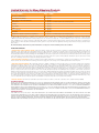
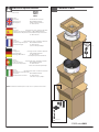
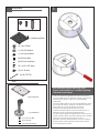
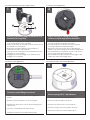
© 2011, Moog Videolarm, Inc. All Rights Reserved
SM5
Compact Vandal-Resistant Surface Mount Dome-5”
www.videolarm.com
Installation and Operation Instructions for the following models:
SM5C2N
Outdoor 5” IP Ready surface mount housing for a small PTZ camera, conduit input from the side and the top of the housing. 24Vac input, with heater/blower. Polycarbonate body and dome. IP66. 1” NPT threads for pedant mount - includes 1.5A 12Vdc camera power supply and wall transformer
SM5CF2
(Fixed camera version of the SM5C2N)
ISM5CN
(Indoor version of the SM5C2N without the heater/blower and 1.5A 12Vdc camera power supply and wall transformer) ISM5CF
(Indoor version of the SM5CF2 without the heater/blower and 1.5A 12Vdc camera power supply and wall transformer)
SM5C24N (24Vac only version of the SM5C2N)
SM5CF24
(Fixed camera version of the SM5C24N)
Before attempting to connect or operate this product, please read these instructions completely.
81-IN5431
01-31-2012
IMPORTANT SAFEGUARDS
1
Read these instructions.
2
Keep these instructions.
3
Heed all warnings
4
Follow all instructions.
5
Do not use this apparatus near water.
6
Clean only with damp cloth.
7
CAUTION
RISK OF ELECTRIC SHOCK
DO NOT OPEN
Do not block any of the ventilation openings. Install in accordance with the
manufacturers instructions.
8
9
SAFETY PRECAUTIONS
Cable Runs- All cable runs must be within permissible distance.
CAUTION: TO REDUCE THE RISK OF
ELECTRIC SHOCK, DO NOT REMOVE
COVER ( OR BACK). NO USER- SERVICEABLE PARTS INSIDE. REFER SEVICING
TO QUALIFIED SERVICE PERSONNEL.
Mounting - This unit must be properly and securely mounted to a supporting
structure capable of sustaining the weight of the unit.
Accordingly:
a. The installation should be made by a qualified installer.
b. The installation should be in compliance with local codes.
c. Care should be exercised to select suitable hardware to install the unit, taking into
account both the composition of the mounting surface and the weight of the unit.
10 Do not install near any heat sources such as radiators, heat registers, stoves, or other
apparatus ( including amplifiers) that produce heat.
11 Do not defeat the safety purpose of the polarized or grounding-type plug. A
polarized plug has two blades with one wider than the other. A grounding type
plug has two blades and a third grounding prong. The wide blade or the third
prong are provided for your safety. When the provided plug does not fit into your
outlet, consult an electrician for replacement of the obsolete outlet.
12 Protect the power cord from being walked on or pinched particularly at plugs,
convenience receptacles, and the point where they exit from the apparatus.
13 Only use attachment/ accessories specified by the manufacturer.
14 Use only with a cart, stand, tripod, bracket, or table specified by the manufacturer,
or sold with the apparatus. When a cart is used, use caution when moving the cart/
apparatus combination to avoid injury from tip-over.
15 Unplug this apparatus during lighting storms or when unused for long periods of time.
16 Refer all servicing to qualified service personnel. Servicing is required when the
apparatus has been damaged in any way, such as power-supply cord or plug is
damaged, liquid has been spilled of objects have fallen into the apparatus, the
The lightning flash with an arrowhead symbol,
within an equilateral triangle, is intended to
alert the user to the presence of non-insulated
“dangerous voltage” within the product’s
enclosure that may be of sufficient magnitude
to constitute a risk to persons.
Este símbolo se piensa para alertar al usuario a la presencia
del “voltaje peligroso no-aisIado” dentro del recinto de los
productos que puede ser un riesgo de choque eléctrico.
Ce symbole est prévu pour alerter I’utilisateur à la presence
“de la tension dangereuse” non-isolée dans la clôture de
produits qui peut être un risque de choc électrique.
Dieses Symbol soll den Benutzer zum Vorhandensein der
nicht-lsolier “Gefährdungsspannung” innerhalb der
Produkteinschließung alarmieren die eine Gefahr des
elektrischen Schlages sein kann.
Este símbolo é pretendido alertar o usuário à presença “di
tensão perigosa non-isolada” dentro do cerco dos produtos
que pode ser um risco de choque elétrico.
Questo simbolo è inteso per avvertire I’utente alla presenza
“di tensione pericolosa” non-isolata all’interno della
recinzione dei prodotti che può essere un rischio di scossa
elettrica.
apparatus has been exposed to rain or moisture, does not operate normally, or
has been dropped.
Be sure to periodically examine the unit and the supporting structure to make sure that the integrity
of the installation is intact. Failure to comply with the foregoing could result in the unit separating
from the support structure and falling, with resultant damages or injury to anyone or anything struck
by the falling unit.
UNPACKING
Unpack carefully. Electronic components can be
damaged if improperly handled or dropped. If an item
appears to have been damaged in shipment, replace
it properly in its carton and notify the shipper.
Be sure to save:
1 The shipping carton and packaging material.
They are the safest material in which to make future
shipments of the equipment.
2 These Installation and Operating Instructions.
SERVICE
If technical support or service is needed, contact us at
the following number:
TECHNICAL SUPPORT
AVAILABLE 24 HOURS
1 - 800 - 554 -1124
The exclamation point within an equilateral
triangle is intended to alert the user to
presence of important operating and
maintenance (servicing) instructions in the
literature accompanying the appliance.
Este símbolo del punto del exclamation se piensa para
alertar al usuario a la presencia de instrucciones importantes
en la literatura que acompaña la aplicación.
Ce symbole de point d’exclamation est prévu pour alerter
l’utilisateur à la presence des instructions importantes dans
la littérature accompagnant l’appareil.
Dieses Ausruf Punktsymbol soll den Benutzer zum
Vorhandensein de wichtigen Anweisungen in der Literatur
alarmieren, die das Gerät begleitet.
Este símbolo do ponto do exclamation é pretendido alertar o
usuário à presença de instruções importantes na literatura
que acompanha o dispositivo.
Questo simbolo del punto del exclamaton è inteso per
avvertire l’utente alla presenza delle istruzioni importanti nella
letteratura che accompagna l'apparecchio.
Limited Warranty for Moog Videolarm Products
Moog Videolarm warrants these products to be free from defects in material or workmanship as follows:
PRODUCT CATEGORY
PARTS \ LABOR
AllEnclosuresandElectronics*
Five(5)Years
Poles/PolEvators™/CamEvator
Three(3)Years
WarriorSeries™/Q-View™/IRIlluminators
Five(5)Years
SViewSeries™
Five(5)Years**6monthsifusedinautoscan/touroperation
Controllers
Five(5)Years
PowerSupplies
Five(5)Years
EcoKit
Three(3)Years
AccessoryBrackets
Five(5)Years
LibertyDome
Three(3)Years
*DeputyDome™,NiteTrac™,IglooDome,PurgeDome™
Three(3)Years**6monthsifusedinautoscan/touroperation
During the labor warranty period, to repair the Product, Purchaser will either return the defective product, freight prepaid, or deliver it to Moog Videolarm
Inc. Decatur GA. The Product to be repaired is to be returned in either its original carton or a similar package affording an equal degree of protection with
a RMA # (Return Materials Authorization number) displayed on the outer box or packing slip. To obtain a RMA# you must contact our Technical Support
Team at 800.554.1124, extension 101. Moog Videolarm will return the repaired Product freight prepaid to Purchaser. Moog Videolarm is not obligated to
provide Purchaser with a substitute unit during the warranty period or at any time. After the applicable warranty period, Purchaser must pay all labor and/or
parts charges.
The limited warranty stated in these product instructions is subject to all of the following terms and conditions.
TERMS AND CONDITIONS
1. NOTIFICATION OF CLAIMS: WARRANTY SERVICE: If Purchaser believes that the Product is defective in material or workmanship, then written notice with an
explanation of the claim shall be given promptly by Purchaser to Moog Videolarm. All claims for warranty service must be made within the warranty period.
If after investigation Moog Videolarm determines the reported problem was not covered by the warranty, Purchaser shall pay Moog Videolarm for the cost of
investigating the problem at its then prevailing per incident billable rate. No repair or replacement of any Product or part thereof shall extend the warranty period
of the entire Product. The specific warranty on the repaired part only shall be in effect for a period of ninety (90) days following the repair or replacement of that
part or the remaining period of the Product parts warranty, whichever is greater.
2. EXCLUSIVE REMEDY: ACCEPTANCE: Purchaser’s exclusive remedy and Moog Videolarm’s sole obligation is to supply (or pay for) all labor necessary to repair any
Product found to be defective within the warranty period and to supply, at no extra charge, new or rebuilt replacements for defective parts.
3. EXCEPTIONS TO LIMITED WARRANTY:Moog Videolarm shall have no liability or obligation to Purchaser with respect to any Product requiring service during the
warranty period which is subjected to any of the following: abuse, improper use, negligence, accident, lightning damage or other acts of God (i.e., hurricanes,
earthquakes), modification, failure of the end-user to follow the directions outlined in the product instructions, failure of the end-user to follow the maintenance
procedures recommended by the International Security Industry Organization, written in product instructions, or recommended in the service manual for the
Product. Furthermore, Moog Videolarm shall have no liability where a schedule is specified for regular replacement or maintenance or cleaning of certain parts
(based on usage) and the end-user has failed to follow such schedule; attempted repair by non-qualified personnel; operation of the Product outside of the
published environmental and electrical parameters, or if such Product’s original identification (trademark, serial number) markings have been defaced, altered,
or removed. Moog Videolarm excludes from warranty coverage Products sold AS IS and/or WITH ALL FAULTS and excludes used Products which have not
been sold by Moog Videolarm to the Purchaser. All software and accompanying documentation furnished with, or as part of the Product is furnished “AS IS”
(i.e., without any warranty of any kind), except where expressly provided otherwise in any documentation or license agreement furnished with the Product. Any
cost associated with removal of defective product and installation of replacement product is not included in this warranty.
4. PROOF OF PURCHASE:The Purchaser’s dated bill of sale must be retained as evidence of the date of purchase and to establish warranty eligibility.
DISCLAIMER OF WARRANTY
EXCEPT FOR THE FOREGOING WARRANTIES, Moog Videolarm HEREBY DISCLAIMS AND EXCLUDES ALL OTHER WARRANTIES, EXPRESS OR IMPLIED,
INCLUDING, BUT NOT LIMITED TO ANY AND/OR ALL IMPLIED WARRANTIES OF MERCHANTABILITY, FITNESS FOR A PARTICULAR PURPOSE AND/OR
ANY WARRANTY WITH REGARD TO ANY CLAIM OF INFRINGEMENT THAT MAY BE PROVIDED IN SECTION 2-312(3) OF THE UNIFORM COMMERCIAL
CODE AND/OR IN ANY OTHER COMPARABLE STATE STATUTE. Moog Videolarm HEREBY DISCLAIMS ANY REPRESENTATIONS OR WARRANTY THAT
THE PRODUCT IS COMPATIBLE WITH ANY COMBINATION OF NON-Moog Videolarm PRODUCTS OR NON-Moog Videolarm RECOMMENDED PRODUCTS
PURCHASER MAY CHOOSE TO CONNECT TO THE PRODUCT.
LIMITATION OF LIABILITY
THE LIABILITY OF Moog Videolarm, IF ANY, AND PURCHASER’S SOLE AND EXCLUSIVE REMEDY FOR DAMAGES FOR ANY CLAIM OF ANY KIND
WHATSOEVER, REGARDLESS OF THE LEGAL THEORY AND WHETHER ARISING IN TORT OR CONTRACT, SHALL NOT BE GREATER THAN THE ACTUAL
PURCHASE PRICE OF THE PRODUCT WITH RESPECT TO WHICH SUCH CLAIM IS MADE. IN NO EVENT SHALL Moog Videolarm BE LIABLE TO PURCHASER
FOR ANY SPECIAL, INDIRECT, INCIDENTAL, OR CONSEQUENTIAL DAMAGES OF ANY KIND INCLUDING, BUT NOT LIMITED TO, COMPENSATION,
REIMBURSEMENT OR DAMAGES ON ACCOUNT OF THE LOSS OF PRESENT OR PROSPECTIVE PROFITS OR FOR ANY OTHER REASON WHATSOEVER.
!
Electrical Specifications
Power 24VAC
Class 2 Only
24 VAC
Accessories:
Camera Power:
Tools Required:
English
Español
Français
Portuguese
Italiano
SM5C2N
SM5CFN
ISM5CN
ISM5CF
Heater/ Blower: 40 Watts
SEE CAMERA MANUAL
Phillips Head Screwdriver
⅝” Allen Wrench
24 VAC
Accesorios:
Calentador: 40 watts, Soplador: 40 Watts
Energía De la Cámara fotográfica: SEE CAMERA MANUAL
Las Herramientas Requirieron: Destornillador Principal Plano Del
⅝” Allen Wrench.
24 VCA
Accessoires :
Réchauffeur:40 watts, Ventilateur: 40 Watts
Puissance D'Appareil-photo : SEE CAMERA MANUAL
Les Outils Ont exigé :
⅝” Allen Wrench.
Tournevis Principal Phillips.
24 VAC
Zusatzgeräte:
Kamera-Energie:
Werkzeuge Erforderten:
Deutsch
Contents of Box
*
(1) Mounting Plate
Heizung: 40 watts, Gebläse: 40 Watts
SEE CAMERA MANUAL
⅝” Allen Wrench
Kreuzkopfhauptschraubenzieher.
(1) Fixed Bracket
(7) 8 x 32 x 3/8" Bolt
(3) 8 x 32 Nuts
(7) 8 x 32 Star Washers
24 VAC
Acessórios:
Calefator:40 watts, Ventilador: 40 Watts
Poder Da Câmera:
SEE CAMERA MANUAL
Ferramentas Requeridas:
⅝” Allen Wrench.
Chave de fenda Principal Phillips.
24 VCA.
Accessori:
Riscaldatore:40 Watts, Ventilatore: 40 Watts
Alimentazione Della Macchina
fotografica:
SEE CAMERA MANUAL
Gli Attrezzi Hanno richiesto:
⅝” Allen Wrench
Cacciavite Capo "phillips".
NOTE: The ISM5CN / ISM5CF (Indoor unit) have no powered accessories
(1) Mounting Plate
(1) 1/4 x 20 Bolt
(1) 1/4 Flat Washer
(1) 1/4 Lock Washer
(4) M3 6mm Bolt
(4) M3 Lock Washers
(7) 8 x 32 x 3/8" bolts
(2) 8 x 32 Nuts
(2) 94-FSCT01
* FIXED units ONLY
1
PACKETS
(4)
(8)
For Surface Mounting using side conduit entrance
(4)
(1) Mounting Plate
(1) 1/4 x 20 Bolt
(1) 1/4 Flat Washer
(1) 1/4 Lock Washer
(4) M3 6mm Bolt
(4) M3 Lock Washers
(7) 8 x 32 x 3/8" bolts
(2) 8 x 32 Nuts
(2) 94-FSCT01
Fixed
Etch knockout slightly with utility knife.
Knock and hammer out ⅞ conduit opening
with blunt screw driver.
(1) Mounting Plate
(1) Fixed Bracket
(7) 8 x 32 x 3/8" Bolt
(3) 8 x 32 Nuts
(7) 8 x 32 Star Washers
• Golpe de gracia del grabado de pistas levemente
con el cuchillo para uso general. Golpee y resuelva la
abertura del conducto del ⅞ con destornillador
embotado.
• Coup de grâce gravure à l'eau forte légèrement avec
le couteau de service. Frappez et résolvez l'ouverture
de conduit de ⅞ avec le tournevis émoussé.
• Ätzung-Ausscheidungswettkampf etwas mit
Gebrauchsmesser. Klopfen Sie und hämmern Sie ⅞
Rohröffnung mit stumpfem Schraubenzieher.
• KO gravura em àgua forte ligeiramente com faca de
serviço público. Bata e resolva a abertura da canalização do ⅞ com chave de fenda sem corte.
• Espulsore incissione all'acquaforte un po'con la lama
pratica. Batti e risolva l'apertura del condotto del ⅞
con il cacciavite smussato.
For Surface Mounting using side conduit entrance
1
For Surface mount applications
2
2
1
3
Drill out (3) mounting holes as shown for # 10
hardware (not supplied)
• Taladre (3) los agujeros de montaje como se muestra
para # el hardware 10 (not supplied)
• Percez (3) les trous de montage comme montré pour #
le matériel 10 (not supplied)
• Bohren Sie (3) Entlüftungslöcher wie gezeigt für #
Hardware 10 heraus (not supplied)
• Fure (3) furos de montagem como mostrado para # a
ferragem 10 (not supplied)
• Estragga (3) fori di montaggio come indicato per #
fissaggi 10 (not supplied)
For Surface mount applications
3
Connect conduit fitting to knockout
Mount securely to ceiling or mounting
surface using the appropriate hardware
• Monte con seguridad a la superficie del techo o de
montaje usando el hardware apropiado
• Montez solidement au plafond ou à la surface de
montage utilisant le matériel approprié
• Bringen Sie sicher zur Decke oder zur Befestigungsfläche unter Verwendung der passenden Hardware an
• Monte firmemente à superfície do teto ou de montagem usando a ferragem apropriada
• Monti saldamente alla superficie di montaggio o del
soffitto per mezzo dei fissaggi adatti
For Pendant or Wall mount bracket applications
4
Remove plug with ⅝” Allen Wrench
• Conecte el conducto que cabe con el golpe de
gracia
• Quite el enchufe con la llave Allen del ⅝”
• Reliez le conduit s'adaptant au coup de grâce
• Enlevez la prise clé Allen avec de ⅝ »
• Schließen Sie das Rohr an, das an Ausscheidungswettkampf passt
• Entfernen Sie Stecker mit ⅝“ Inbusschlüssel
• Conecte a canalização que cabe ao KO
• Colleghi il condotto che si adatta all'espulsore
• Remova o plugue com chave Allen do ⅝ de”
• Rimuova la spina con chiave di Allen del ⅝„
For Pendant or Wall mount applications
For Pendant or Wall mount applications
5
6
Seal pipe threads with teflon tape supplied
with outdoor housings
Thread housing to optional pendent pipe or
wall mount bracket
• Hilos de rosca de pipa del sello con la cinta del Teflon
suministrada las cubiertas al aire libre
• Filetages de tuyauterie de joint avec la bande de
teflon fournie avec les logements extérieurs
• Dichtungsrohrgewinde mit dem Teflonklebeband
geliefert mit im Freiengehäusen
• Linhas de tubulação do selo com a fita do Teflon
fornecida com as carcaças ao ar livre
• Filetti di tubo della guarnizione con nastro adesivo del
Teflon fornito con gli alloggiamenti esterni
• Hilo de rosca que contiene al soporte pendiente
opcional del montaje de la pipa o de la pared
• Fil logeant à la parenthèse en suspens facultative de
bâti de pipe ou de mur
• Gewinde, das zum wahlweise freigestellten pendent
Rohr- oder Wandeinfassungshaltewinkel unterbringt
• Linha que abriga ao suporte pendent opcional da
montagem da tubulação ou da parede
• Filetto che alloggia alla staffa pendent facoltativa del
supporto della parete o del tubo
For Pendant or Wall mount applications
7
Finish assembly with Pendant or Wall mount (not supplied)
• Asamblea del final con el montaje pendiente o de la pared (not supplied)
• Finition avec le bâti en suspens ou de mur (not supplied)
• Ende mit Pendent oder Wandeinfassung (not supplied)
• Conjunto do revestimento com a montagem Pendent ou da parede (not supplied)
• Assemblea di rivestimento con il supporto della parete o Pendent (not supplied)
For indoor ceiling application with electrical box
8
9
Housing is designed to mount to 411/16 x 411/16”
electrical box. Mount box securely to ceiling structure
Drill out appropriate (2) mounting holes
• La cubierta se diseña para montar a 411/16 x 411/16” caja eléctrica.
Caja del montaje con seguridad a la estructura del techo
• Le logement est conçu pour monter dans 411/16 x 411/16 » boîte
électrique. Boîte de bâti solidement à la structure de plafond
• Gehäuse ist entworfen, um zu 411/16 x 411/16“ elektrischem Kasten
anzubringen. Einfassungskasten sicher zur Deckenstruktur
• Taladre (2) los agujeros de montaje apropiados
• Percez (2) les trous de montage appropriés
• Bohren Sie passende (2) Entlüftungslöcher heraus
• A carcaça é projetada montar a 411/16 x 411/16” de caixa elétrica.
Caixa da montagem firmemente à estrutura do teto
• Fure (2) furos de montagem apropriados
• L'alloggiamento è destinato per montare a 411/16 x 411/16„ di scatola
elettrica. Contenitore di supporto saldamente alla struttura del soffitto
• Estragga adatto (2) fori di montaggio
10
Secure with appropriate mounting screws
• Asegure con los tornillos de montaje apropiados
11
Feed wiring through threaded hole
• Fixez avec les vis de support appropriées
• Cableado de la alimentación a través del agujero
roscado
• Câblage d'alimentation par le trou fileté
• Sichern Sie mit passenden Befestigungsschrauben
• Zufuhrverdrahtung durch verlegtes Loch
• Fixe com os parafusos de montagem apropriados
• Fiação da alimentação através do furo rosqueado
• Fissi con le viti di montaggio adatte
• Collegamenti dell'alimentazione attraverso il foro
filettato
12
Axis M-10
Axis 207
Camera hole
pattern
Adding
Spacers
Attach Axis camera mount to camera base plate. Use (4) 1” spacers and attach camera base plate to housing.
• Ate el montaje de cámara del eje al embase de la cámara. Utilice (4) los” espaciadores 1 y ate el embase de la cámara a la
cubierta.
• Attachez la monture de caméra d'axe à l'embase d'appareil-photo. Employez (4) les » entretoises 1 et attachez l'embase d'appareilphoto au logement.
• Bringen Sie Mittellinienkameraeinfassung zur Grundplatte der Kamera an. Verwenden Sie (4)“ Distanzscheiben 1 und bringen Sie
Grundplatte der Kamera zum Gehäuse an.
• Una a montagem de câmera da linha central à placa baixa da câmera. Use (os” espaçadores 4) 1 e una a placa baixa da câmera
à carcaça.
• Attacchi il supporto di macchina fotografica di asse alla base di appoggio della macchina fotografica. Usi (4)„ i distanziatori 1 ed
attaccano la base di appoggio della macchina fotografica ad alloggiamento.
Arecont AV5100
13
REMOVE
Remove center section from fixed camera bracket. Attach to mounting plate with hardware provided. Secure and
complete wiring connections.
• Quite la sección de centro del soporte fijo de la cámara. Ate a la pletina con el hardware proporcionado. Asegure y termine las
conexiones del cableado.
• Enlevez la section centrale de la parenthèse fixe d'appareil-photo. Attachez au plat de support avec le matériel fourni. Fixez et
accomplissez les raccordements de câblage.
• Entfernen Sie mittleren Abschnitt von örtlich festgelegtem Kamerahaltewinkel. Bringen Sie zur Montageplatte mit der bereitgestellten
Hardware an. Sichern Sie und schließen Sie Verdrahtungsanschlüsse ab.
• Remova a seção center de suporte fixo da câmera. Una à placa de montagem com a ferragem fornecida. Fixe e termine conexões
da fiação.
• Rimuova la sezione concentrare dalla staffa fissa della macchina fotografica. Attacchi al giunto di supporto con fissaggi forniti. Assicuri
e completi i collegamenti dei collegamenti.
Axis 216 CAMERA
14
(13mm) ½"
Use this hole
pattern
(52mm) 2"
Install (4) .5” + (4) 2.0”
spacers to center bosses
• Instale (4) .5” + (4) 2.0” espaciadores para
centrar los jefes
Secure camera quick release
mounting plate with #8 hardware
provided
• Pletina segura del lanzamiento rápido de la cámara
con el hardware #8 proporcionado
Tighten hardware and
complete wiring
• Apriete el hardware y termine el cableado
• Installez (4) .5 » + (4) 2.0 » entretoises pour
centrer des patrons
• Le plat de support bloqué de dégagement rapide
d'appareil-photo avec le matériel #8 a fourni
• Serrez la visserie et accomplissez le câblage
• Bringen Sie (4) .5“ + (4) 2.0“ Distanzscheiben
an, um Chefs zu zentrieren
• Sichere Montageplatte der schnellen Freigabe der
Kamera mit Hardware #8 stellte zur Verfügung
• Ziehen Sie Hardware fest und schließen Sie
Verdrahtung ab
• Instale (4) .5” + (4) 2.0” espaçadores para
centrar saliências
• Placa de montagem segura da liberação rápida
da câmera com a ferragem #8 fornecida
• Aperte a ferragem e termine a fiação
• Installi (4) .5„ + (4) 2.0„ distanziatori per
concentrarsi le sporgenze
• Il giunto di supporto sicuro del rilascio rapido della
macchina fotografica con fissaggi #8 ha fornito
• Stringa i fissaggi e completi i collegamenti
Axis 213/Canon VB C10R
15
Use this hole
pattern
Install (4) 1” spacer to
center bosses
• Instale (4) 1” espaciador para centrar los
jefes
• Installez (4) 1 » entretoise pour centrer des
patrons
• Bringen Sie (4) 1“ Distanzscheibe an, um
Chefs zu zentrieren
• Instale (4) 1” espaçador para centrar
saliências
(25mm) 1"
Secure camera quick release
mounting plate with #8 hardware
provided
• Pletina segura del lanzamiento rápido de la cámara
con el hardware #8 proporcionado
• Le plat de support bloqué de dégagement rapide
d'appareil-photo avec le matériel #8 a fourni
• Sichere Montageplatte der schnellen Freigabe der
Kamera mit Hardware #8 stellte zur Verfügung
• Placa de montagem segura da liberação rápida da
câmera com a ferragem #8 fornecida
• Installi (4) 1„ distanziatore per concentrarsi le
• Il giunto di supporto sicuro del rilascio rapido della
sporgenze
macchina fotografica con fissaggi #8 ha fornito
Tighten hardware and
complete wiring
• Apriete el hardware y termine el cableado
• Serrez la visserie et accomplissez le câblage
• Ziehen Sie Hardware fest und schließen Sie
Verdrahtung ab
• Aperte a ferragem e termine a fiação
• Stringa i fissaggi e completi i collegamenti
AXIS 215 CAMERA
16
(13mm) ½"
Use this hole
pattern
(25mm) 1"
Install (4) .5” + (4) 1.0”
spacers to center bosses
Secure camera quick release
mounting plate with #8
hardware provided
• Instale (4) .5” + (4) 1.0” espaciadores para
centrar los jefes
• Pletina segura del lanzamiento rápido de la
cámara con el hardware #8 proporcionado
• Installez (4) .5 » + (4) 1.0 » entretoises pour
centrer des patrons
• Le plat de support bloqué de dégagement
rapide d'appareil-photo avec le matériel #8 a
fourni
• Bringen Sie (4) .5“ + (4) 1.0“ Distanzscheiben
an, um Chefs zu zentrieren
• Sichere Montageplatte der schnellen Freigabe
der Kamera mit Hardware #8 stellte zur Verfügung
• Instale (4) .5” + (4) 1.0” espaçadores para
centrar saliências
• Placa de montagem segura da liberação rápida
da câmera com a ferragem #8 fornecida
• Installi (4) .5„ + (4) 1.0„ distanziatori per
concentrarsi le sporgenze
• Il giunto di supporto sicuro del rilascio rapido della
macchina fotografica con fissaggi #8 ha fornito
Tighten hardware and
complete wiring
• Apriete el hardware y termine el cableado
• Serrez la visserie et accomplissez le câblage
• Ziehen Sie Hardware fest und schließen Sie
Verdrahtung ab
• Aperte a ferragem e termine a fiação
• Stringa i fissaggi e completi i collegamenti
Canon VB-C50iR CAMERA
17
(13mm) ½"
Use this hole
pattern
(25mm) 1"
Install (4) .5” + (4) 1.0”
spacers to center bosses
Secure camera quick release
mounting plate with #8
hardware provided
• Instale (4) .5” + (4) 1.0” espaciadores para
centrar los jefes
• Pletina segura del lanzamiento rápido de la
cámara con el hardware #8 proporcionado
• Installez (4) .5 » + (4) 1.0 » entretoises pour
centrer des patrons
• Le plat de support bloqué de dégagement
rapide d'appareil-photo avec le matériel #8 a
fourni
• Bringen Sie (4) .5“ + (4) 1.0“ Distanzscheiben
an, um Chefs zu zentrieren
• Sichere Montageplatte der schnellen Freigabe
der Kamera mit Hardware #8 stellte zur Verfügung
• Instale (4) .5” + (4) 1.0” espaçadores para
centrar saliências
• Placa de montagem segura da liberação rápida
da câmera com a ferragem #8 fornecida
• Installi (4) .5„ + (4) 1.0„ distanziatori per
concentrarsi le sporgenze
• Il giunto di supporto sicuro del rilascio rapido della
macchina fotografica con fissaggi #8 ha fornito
Tighten hardware and
complete wiring
• Apriete el hardware y termine el cableado
• Serrez la visserie et accomplissez le câblage
• Ziehen Sie Hardware fest und schließen Sie
Verdrahtung ab
• Aperte a ferragem e termine a fiação
• Stringa i fissaggi e completi i collegamenti
Canon VC-C50iR CAMERA
18
Use this hole
pattern
(25mm) 1"
(25mm) 1"
Install (4) .5” + (4) 1.0”
spacers to center bosses
Secure camera quick release
mounting plate with #8
hardware provided
• Instale (4) .5” + (4) 1.0” espaciadores para
centrar los jefes
• Pletina segura del lanzamiento rápido de la
cámara con el hardware #8 proporcionado
• Installez (4) .5 » + (4) 1.0 » entretoises pour
centrer des patrons
• Le plat de support bloqué de dégagement
rapide d'appareil-photo avec le matériel #8 a
fourni
• Bringen Sie (4) .5“ + (4) 1.0“ Distanzscheiben
an, um Chefs zu zentrieren
• Sichere Montageplatte der schnellen Freigabe
der Kamera mit Hardware #8 stellte zur Verfügung
• Instale (4) .5” + (4) 1.0” espaçadores para
centrar saliências
• Placa de montagem segura da liberação rápida
da câmera com a ferragem #8 fornecida
• Installi (4) .5„ + (4) 1.0„ distanziatori per
concentrarsi le sporgenze
• Il giunto di supporto sicuro del rilascio rapido della
macchina fotografica con fissaggi #8 ha fornito
Tighten hardware and
complete wiring
• Apriete el hardware y termine el cableado
• Serrez la visserie et accomplissez le câblage
• Ziehen Sie Hardware fest und schließen Sie
Verdrahtung ab
• Aperte a ferragem e termine a fiação
• Stringa i fissaggi e completi i collegamenti
Canon VB 300/Acti ACM 8511 CAMERA
19
Use this hole
pattern
(25mm) 1"
Install (4) 1” spacer to
center bosses
Secure camera quick release
mounting plate with #8 hardware
provided
• Instale (4) 1” espaciador para centrar los
jefes
• Pletina segura del lanzamiento rápido de la cámara
con el hardware #8 proporcionado
• Installez (4) 1 » entretoise pour centrer des
patrons
• Le plat de support bloqué de dégagement rapide
d'appareil-photo avec le matériel #8 a fourni
• Bringen Sie (4) 1“ Distanzscheibe an, um
Chefs zu zentrieren
• Instale (4) 1” espaçador para centrar
saliências
• Installi (4) 1„ distanziatore per concentrarsi le
sporgenze
• Sichere Montageplatte der schnellen Freigabe der
Kamera mit Hardware #8 stellte zur Verfügung
• Placa de montagem segura da liberação rápida
da câmera com a ferragem #8 fornecida
• Il giunto di supporto sicuro del rilascio rapido della
macchina fotografica con fissaggi #8 ha fornito
Tighten hardware and
complete wiring
• Apriete el hardware y termine el cableado
• Serrez la visserie et accomplissez le câblage
• Ziehen Sie Hardware fest und schließen Sie
Verdrahtung ab
• Aperte a ferragem e termine a fiação
• Stringa i fissaggi e completi i collegamenti
Acti ACM 8201/ ACM 8211 CAMERA
20
Use this hole
pattern
Install (4) 1” spacer to
center bosses
• Instale (4) 1” espaciador para centrar los
jefes
(25mm) 1"
Secure camera quick release
mounting plate with #8 hardware
provided
• Pletina segura del lanzamiento rápido de la cámara
con el hardware #8 proporcionado
• Installez (4) 1 » entretoise pour centrer des
patrons
• Le plat de support bloqué de dégagement rapide
d'appareil-photo avec le matériel #8 a fourni
• Bringen Sie (4) 1“ Distanzscheibe an, um
Chefs zu zentrieren
• Sichere Montageplatte der schnellen Freigabe der
Kamera mit Hardware #8 stellte zur Verfügung
• Instale (4) 1” espaçador para centrar
saliências
• Placa de montagem segura da liberação rápida da
câmera com a ferragem #8 fornecida
• Installi (4) 1„ distanziatore per concentrarsi le
sporgenze
• Il giunto di supporto sicuro del rilascio rapido della
macchina fotografica con fissaggi #8 ha fornito
21
Tighten hardware and
complete wiring
• Apriete el hardware y termine el cableado
• Serrez la visserie et accomplissez le câblage
• Ziehen Sie Hardware fest und schließen Sie
Verdrahtung ab
• Aperte a ferragem e termine a fiação
• Stringa i fissaggi e completi i collegamenti
Use this hole
pattern
Secure camera quick release mounting plate
with #8 hardware provided
• Pletina segura del lanzamiento rápido de la cámara con el hardware
#8 proporcionado
• Le plat de support bloqué de dégagement rapide d'appareil-photo
avec le matériel #8 a fourni
• Sichere Montageplatte der schnellen Freigabe der Kamera mit
Hardware #8 stellte zur Verfügung
• Placa de montagem segura da liberação rápida da câmera com a
ferragem #8 fornecida
• Il giunto di supporto sicuro del rilascio rapido della macchina fotografica
con fissaggi #8 ha fornito
Tighten hardware and complete wiring
• Apriete el hardware y termine el cableado
• Serrez la visserie et accomplissez le câblage
• Ziehen Sie Hardware fest und schließen Sie Verdrahtung ab
• Aperte a ferragem e termine a fiação
• Stringa i fissaggi e completi i collegamenti
Panasonic BB-HCM381 / BBHCM580 / KX-HCM280A CAMERA
22
Use this hole
pattern
Install (4) ½” spacers to
center bosses
• Instale (4) espaciadores del ½ los” para
centrar los jefes
• Entretoises installez (4) ½ des » pour centrer
des patrons
• Bringen Sie (4) ½“ Distanzscheiben an, um
Chefs zu zentrieren
• Instale (4) espaçadores do ½” para centrar
saliências
• Installi (4) distanziatori del ½„ per concentrarsi le sporgenze
(13mm) ½"
Secure camera quick release
mounting plate with #8
hardware provided
• Pletina segura del lanzamiento rápido de la
cámara con el hardware #8 proporcionado
• Le plat de support bloqué de dégagement
rapide d'appareil-photo avec le matériel #8 a
fourni
• Sichere Montageplatte der schnellen Freigabe
der Kamera mit Hardware #8 stellte zur
Verfügung
• Placa de montagem segura da liberação
rápida da câmera com a ferragem #8
fornecida
• Il giunto di supporto sicuro del rilascio rapido
della macchina fotografica con fissaggi #8 ha
fornito
Tighten hardware and
complete wiring
• Apriete el hardware y termine el cableado
• Serrez la visserie et accomplissez le câblage
• Ziehen Sie Hardware fest und schließen Sie
Verdrahtung ab
• Aperte a ferragem e termine a fiação
• Stringa i fissaggi e completi i collegamenti
Panasonic WV-CF294 - WV-CF284
23
(13mm) ½"
(52mm) 2"
Install (4) .5” + (4) 2.0”
spacers to center bosses
Secure camera quick release
mounting plate with #8
hardware provided
• Instale (4) .5” + (4) 2.0” espaciadores para
centrar los jefes
• Pletina segura del lanzamiento rápido de la
cámara con el hardware #8 proporcionado
• Installez (4) .5 » + (4) 2.0 » entretoises pour
centrer des patrons
• Le plat de support bloqué de dégagement
rapide d'appareil-photo avec le matériel #8 a
fourni
• Bringen Sie (4) .5“ + (4) 2.0“ Distanzscheiben
an, um Chefs zu zentrieren
• Sichere Montageplatte der schnellen Freigabe
der Kamera mit Hardware #8 stellte zur Verfügung
• Instale (4) .5” + (4) 2.0” espaçadores para
centrar saliências
• Placa de montagem segura da liberação rápida
da câmera com a ferragem #8 fornecida
• Installi (4) .5„ + (4) 2.0„ distanziatori per
concentrarsi le sporgenze
• Il giunto di supporto sicuro del rilascio rapido della
macchina fotografica con fissaggi #8 ha fornito
Secure camera safety screw
• Asegure el tornillo de la seguridad de la
cámara
• Fixez la vis de sûreté d'appareil-photo
• Sichern Sie Kamerasicherheitsschraube
• Fixe o parafuso da segurança da câmera
• Fissi la vite di sicurezza della macchina
fotografica
Panasonic WV-NF284 - WV-NF302 CAMERA
24
(25mm) 1"
Install (4) 1” spacer to
center bosses
• Instale (4) 1” espaciador para centrar los
jefes
• Installez (4) 1 » entretoise pour centrer des
patrons
• Bringen Sie (4) 1“ Distanzscheibe an, um
Chefs zu zentrieren
• Instale (4) 1” espaçador para centrar
saliências
• Installi (4) 1„ distanziatore per concentrarsi le
sporgenze
Secure camera quick release
mounting plate with #8
hardware provided
• Pletina segura del lanzamiento rápido de la
cámara con el hardware #8 proporcionado
• Le plat de support bloqué de dégagement
rapide d'appareil-photo avec le matériel #8 a
fourni
• Sichere Montageplatte der schnellen Freigabe
der Kamera mit Hardware #8 stellte zur
Verfügung
• Placa de montagem segura da liberação
rápida da câmera com a ferragem #8
fornecida
• Il giunto di supporto sicuro del rilascio rapido
della macchina fotografica con fissaggi #8 ha
fornito
Secure camera safety screw
• Asegure el tornillo de la seguridad de la
cámara
• Fixez la vis de sûreté d'appareil-photo
• Sichern Sie Kamerasicherheitsschraube
• Fixe o parafuso da segurança da câmera
• Fissi la vite di sicurezza della macchina
fotografica
Panasonic WV-NS202 CAMERA
25
(13mm) ½"
Install (4) ½” spacers to
center bosses
Secure camera quick release
mounting plate with #8 hardware
provided
• Instale (4) espaciadores del ½ los” para
centrar los jefes
• Pletina segura del lanzamiento rápido de la cámara
con el hardware #8 proporcionado
• Entretoises installez (4) ½ des » pour centrer
des patrons
• Le plat de support bloqué de dégagement rapide
d'appareil-photo avec le matériel #8 a fourni
• Bringen Sie (4) ½“ Distanzscheiben an, um
Chefs zu zentrieren
• Sichere Montageplatte der schnellen Freigabe der
Kamera mit Hardware #8 stellte zur Verfügung
• Instale (4) espaçadores do ½” para centrar
saliências
• Placa de montagem segura da liberação rápida da
câmera com a ferragem #8 fornecida
• Installi (4) distanziatori del ½„ per concentrarsi le sporgenze
• Il giunto di supporto sicuro del rilascio rapido della
macchina fotografica con fissaggi #8 ha fornito
Tighten hardware and
complete wiring
• Apriete el hardware y termine el cableado
• Serrez la visserie et accomplissez le câblage
• Ziehen Sie Hardware fest und schließen Sie
Verdrahtung ab
• Aperte a ferragem e termine a fiação
• Stringa i fissaggi e completi i collegamenti
Toshiba IKWB21A CAMERA
26
(13mm) ½"
Install (4) ½” spacers to
center bosses
Secure camera quick release
mounting plate with #8 hardware
provided
• Instale (4) espaciadores del ½ los” para
centrar los jefes
• Pletina segura del lanzamiento rápido de la cámara
con el hardware #8 proporcionado
• Entretoises installez (4) ½ des » pour centrer
des patrons
• Le plat de support bloqué de dégagement rapide
d'appareil-photo avec le matériel #8 a fourni
• Bringen Sie (4) ½“ Distanzscheiben an, um
Chefs zu zentrieren
• Sichere Montageplatte der schnellen Freigabe der
Kamera mit Hardware #8 stellte zur Verfügung
• Instale (4) espaçadores do ½” para centrar
saliências
• Placa de montagem segura da liberação rápida da
câmera com a ferragem #8 fornecida
• Installi (4) distanziatori del ½„ per concentrarsi le sporgenze
• Il giunto di supporto sicuro del rilascio rapido della
macchina fotografica con fissaggi #8 ha fornito
Tighten hardware and
complete wiring
• Apriete el hardware y termine el cableado
• Serrez la visserie et accomplissez le câblage
• Ziehen Sie Hardware fest und schließen Sie
Verdrahtung ab
• Aperte a ferragem e termine a fiação
• Stringa i fissaggi e completi i collegamenti
ELMO 400 CAMERA
27
(13mm) ½"
Install (4) ½” spacers to
center bosses
Secure camera quick release
mounting plate with #8 hardware
provided
• Instale (4) espaciadores del ½ los” para
centrar los jefes
• Pletina segura del lanzamiento rápido de la cámara
con el hardware #8 proporcionado
• Entretoises installez (4) ½ des » pour centrer
des patrons
• Le plat de support bloqué de dégagement rapide
d'appareil-photo avec le matériel #8 a fourni
• Bringen Sie (4) ½“ Distanzscheiben an, um
Chefs zu zentrieren
• Sichere Montageplatte der schnellen Freigabe der
Kamera mit Hardware #8 stellte zur Verfügung
• Instale (4) espaçadores do ½” para centrar
saliências
• Placa de montagem segura da liberação rápida da
câmera com a ferragem #8 fornecida
• Installi (4) distanziatori del ½„ per concentrarsi le sporgenze
• Il giunto di supporto sicuro del rilascio rapido della
macchina fotografica con fissaggi #8 ha fornito
Tighten hardware and
complete wiring
• Apriete el hardware y termine el cableado
• Serrez la visserie et accomplissez le câblage
• Ziehen Sie Hardware fest und schließen Sie
Verdrahtung ab
• Aperte a ferragem e termine a fiação
• Stringa i fissaggi e completi i collegamenti
ELMO 401 CAMERA
28
(13mm) ½"
(52mm) 2"
Install (4) .5” + (4) 1.0”
spacers to center bosses
• Instale (4) .5” + (4) 1.0” espaciadores para
centrar los jefes
• Installez (4) .5 » + (4) 1.0 » entretoises pour
centrer des patrons
Secure camera quick release
mounting plate with #8 hardware
provided
• Pletina segura del lanzamiento rápido de la cámara
con el hardware #8 proporcionado
• Le plat de support bloqué de dégagement rapide
d'appareil-photo avec le matériel #8 a fourni
• Bringen Sie (4) .5“ + (4) 1.0“ Distanzscheiben • Sichere Montageplatte der schnellen Freigabe der
an, um Chefs zu zentrieren
Kamera mit Hardware #8 stellte zur Verfügung
• Instale (4) .5” + (4) 1.0” espaçadores para
centrar saliências
• Placa de montagem segura da liberação rápida da
câmera com a ferragem #8 fornecida
• Installi (4) .5„ + (4) 1.0„ distanziatori per
concentrarsi le sporgenze
• Il giunto di supporto sicuro del rilascio rapido della
macchina fotografica con fissaggi #8 ha fornito
Tighten hardware and
complete wiring
• Apriete el hardware y termine el cableado
• Serrez la visserie et accomplissez le câblage
• Ziehen Sie Hardware fest und schließen Sie
Verdrahtung ab
• Aperte a ferragem e termine a fiação
• Stringa i fissaggi e completi i collegamenti
For connecting Heater and Blower power
29
24VAC power for Heater blower connect to
PCB
• la energía 24VAC para el soplador del calentador
conecta con el PWB
• la puissance 24VAC pour le ventilateur de réchauffeur
se relient à la carte
• Energie 24VAC für Heizungsgebläse schließen an PWB
an
• o poder 24VAC para o ventilador do calefator conecta
ao PWB
• il potere 24VAC per il ventilatore del riscaldatore si
collega al PWB
30
Connect power to (2) input terminals labled
“IN”
• Conecte la energía con (2) los terminales entrados
etiquetados “EN”
• Reliez la puissance (2) aux bornes entrées marquées «
DANS »
• Schließen Sie Energie an (2) die eingegebenen
beschrifteten Anschlüß „IN“ an
• Conecte o poder (2) aos terminais entrados etiquetados “EM”
• Colleghi il potere (2) ha immesso i terminali identificati
“IN„
31
32
Wire Gauge
5.5
10
20
30
40
50
60
70
24 VAC OUTPUT
FOR CAMERA
80
Power requirements for Heater/Blower 40 watt
• Requisitos de energía para el calentador/el soplador 40
vatios
• Alimentation électrique pour le réchauffeur/ventilateur
40 watts
• Leistungsbedarf für Heizung/Gebläse 40 Watt
• Exigências de poder para o calefator/ventilador 40
watts
• Requisiti di potere del riscaldatore/ventilatore 40 watt
33
(1.5 Amps Max)
Layout for model with 12VDC power supply
• Disposición del modelo con la fuente de alimentación
12VDC
• Disposition de modèle avec l'alimentation de l'énergie
12VDC
• Plan des Modells mit 12VDC Spg.Versorgungsteil
• Disposição do modelo com fonte de alimentação
12VDC
• Disposizione del modello con l'alimentazione elettrica
12VDC
,5
22
Total vA
consumed
ft
,75
20
1,0
18
1,5
16
2,5
14
400
m
120
600
960
121
182
292
180
300
480
800
4
12
6
10
-
-
2
MM
AWG
1300
36.5
54.9
91.4
146
243
396
86
141
225
358
571
905
1440
27.1
43.0
68.6
109
174
275
438
65
90
130
225
350
525
830
19.8
27.4
39.6
68.6
106
160
252
44
70
112
179
285
452
720
13.4
21.3
34.1
54.6
86.9
138
219
56
90
143
228
362
576
35
10.6
17.1
27.4
43.6
69.5
110
175
29
47
75
119
190
301
480
9.4
14.3
22.9
36.2
57.9
91.7
146
40
64
102
163
258
411
8.8
12.2
19.5
31.1
49.7
78.6
125
34
55
85
140
215
340
25
31
7.6
10.3
16.8
25.9
42.7
65.5
103
These are recommended maximum distances
for 24VAC with a 10% voltage drop.
• Éstos se recomiendan las distancias máximas para
24VAC con una caída de voltaje del 10%.
• Ceux-ci sont recommandés des distances maximum
pour 24VAC avec une chute de tension de 10%.
• Diese werden maximale Abstände für 24VAC mit
einem 10% Spannungsabfall empfohlen.
• Estes são recomendados distâncias máximas para
24VAC com uma queda de tensão de 10%.
• Questi sono suggeriti distanze massime per 24VAC con
una differenza de potenziale di 10%.
34
Input for 12VDC model is same as standard
unit
• La entrada para el modelo 12VDC es igual que unidad
estándar
• L'entrée pour le modèle 12VDC correspond l'unité
standard
• Eingang für Modell 12VDC ist selbe wie Standardmaßeinheit
• A entrada para o modelo 12VDC é mesma que a
unidade padrão
• L'input per il modello 12VDC è stesso dell'unità standard
35
36
12VDC Power Connector
Locate 12VDC Power Connector
Connect power and control wires to camera
• Disposición del modelo con la fuente de alimentación
12VDC
• Conecte la energía y controle los alambres a la
cámara
• Disposition de modèle avec l'alimentation de l'énergie
12VDC
• Reliez la puissance et commandez les fils à l'appareilphoto
• Plan des Modells mit 12VDC Spg.Versorgungsteil
• Schließen Sie Energie an und steuern Sie Drähte zur
Kamera
• Disposição do modelo com fonte de alimentação
12VDC
• Disposizione del modello con l'alimentazione elettrica
12VDC
37
Install security screw, if desired
• Conecte o poder e controle fios à câmera
• Colleghi il potere e controlli i legare alla macchina
fotografica
38
Attach lanyard loop to hook
• Instale el tornillo de la seguridad, si está deseado
• Ate el lazo del acollador al gancho
• Installez la vis de sécurité, si désiré
• Attachez la boucle de lanière au crochet
• Bringen Sie Sicherheitsschraube an, wenn Sie gewünscht werden
• Instale o parafuso da segurança, se desejado
• Bringen Sie Abzuglinieschleife zum Haken an
• Avviti la vite di sicurezza, se voluto
• Attacchi il ciclo della cordicella al gancio
• Una o laço do colhedor ao gancho
40
39
Clean dome with MILD soap and water ONLY
Secure Dome Assembly to housing
• Limpie la bóveda con el jabón y agua SUAVES SOLAMENTE
• Nettoyez le dôme avec de l'eau le savon et DOUX
SEULEMENT
• Säubern Sie Haube mit NUR MILDER Seife und Wasser
• Asegure la asamblea de la bóveda a la cubierta
• Fixez l'Assemblée de dôme au logement
• Befestigen Sie Haube an Gehäuse
• Limpe a abóbada com o sabão e água SUAVES
SOMENTE
• Pulisca la cupola con sapone ed acqua DELICATI
SOLTANTO
• Fixe o conjunto da abóbada à carcaça
• Assicuri l'Assemblea della cupola ad alloggiamento
Replacement Parts List
Item
Number
PISM5V
1
5
2
6
3
7
4
Part
Number
Comments
1
RP0SM5TR
Replace Trim Ring Assembly
2
RPDC5
Dome and Gasket
3
RP0SM5HG
Housing
4
RP95FSP01
1” NPT Plug
5
RP0SM5HB
Heater / Blower Unit
6
RP0SM5BKT
Heater Bracket
7
RP0SM5PCB
Accessory PCB
Product Registration/Warranty
Thank you for choosing Moog Videolarm. We value your patronage and are solely committed to providing you with the highest
quality products available and superior customer service. Should a problem arise, rest assure that Moog Videolarm stands behind its products by offering impressive warranty plans: 3 Years on all Housings, Poles, Power Supplies, and Accessories and 5 Years on camera systems (SView, QView, Warriors), and InfraRed Illuminators.
Register Your Products Online
Take a few moments and validate your purchase via the Online Product Registration Form at
www.videolarm.com/productregistration.jsp
Register your recent Moog Videolarm purchases and benefit from the following:
• Simple and Trouble-Free RMA process
• Added into customer database to receive product updates / news
• Eliminate the need to archive original purchase documents:
Receipts, Purchase Orders, etc…