1
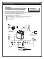
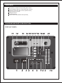
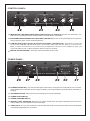
PCMX265B
PORTABLE SOUND SYSTEM FOR USB AND SD CARD
USER'S MANUAL
www.PyleAudio.com
QUICK SETUP GUIDE
1. Make sure all items listed on the front of this guide are included in the box.
2. READ SAFETY INSTRUCTION BOOKLET BEFORE USING
THE PRODUCT.
3. MAKE SURE THAT YOU HAVE COMPLETELY CHARGED
BOX CONTENTS
Battery Powered Amplifier
THE BATTERY PRIOR TO FIRST USE FOR MAXIMUM
Power Cable (Standard IEC)
BATTERY LIFE.
4. Study this setup diagram.
5. Place product in an appropriate position for operation.
6. Make sure all input devices such as microphones,CD players, mp3 players, and linked amplifiers/
PAs are turned off and volume settings are set at "zero"
7. Connect all devices as shown above.
8. Connect the stereo outputs to the power amplifier(s), tape decks, and/or audio sources.
9. Switch everything on in the following order.
audio input sources ( i.e. microphones, instruments, CD/MP3 Players)
last, any amplifiers
10. When turning off, always reverse this operation by.
turming off amplifiers
last, any input devices
AC F US E IN PU T RA NG E
CHARGE
USB/SD
ON
SOUND SYSTEM
BATTERY LEVEL
LINK
OUTPUT
ON
OFF
LOW
1
2
3
OFF
110 -T 75 0m AL 250 V
10 0- 12 0V- 60 Hz 2 0W
23 0- T3 15 mA L 250V
22 0- 24 0V- 50 Hz 2 0W
USB/SD
L
R
To RCA input on additional
(Cable sold separately)
MIC 1 BALANCED
GAIN
INSTRUMENT/MIC 2
GAIN
USB/SD/AUX
GAIN
MASTER
VOLUME
POWER
LEFT
RIGHT
L
R
(Cable sold separately)
OR
FEATURES
Microphone 1 balanced input with gain control.
Instrument/Microphone 2 input with gain control.
Auxuliary input with gain control (stereo RCA).
Master Volume Control.
Voltage Selector.
Link Output jack
Produce size:349x458x273mm(wxhxd)
DIAGRAM AND PARTS DESCRIPTION
DISPLAY PANEL:
11 12
13 14 15 1617 18 19 20
21
Push
USB
USB
SD
Track/Folder
Search
SD
USB/SD
Single
Pitch
Repeat
Time
Reverse
IN
OUT
Reloop
Loop
1
2
3 4
5
6
78 9
10
1. CUE: To define and record a return point from which playback it again.
2. PLAY/PAUSE: Each time you press the PLAY/PAUSE button, the operation changes from play to pause or from
pause to play.
3. REVERSE: Push the reverse button to play your track in reverse, push the reverse button again to
cancel this feature.
4. SKIP I<< BUTTON: Use this switch to restart the track or to select the last track.
5. IN BUTTON (LOOP SYSTEM): This button sets the beginning point of the loop and light is illuminate.
6. OUT BUTTON (LOOP BUTTON): When you press this button, you set the end point of the seamless loop
and you start the loop. To finish the loop, press again this button.
7. RELOOP BUTTON (LOOP SYSTEM): This button is used to start the last saved loop. To finish the loop,
press the reloop button.
8. SKIP >>I BUTTON: Use this knob to select the next track.
9. ID3: When you pressing the ID3 button, Able to show the name of songs on led display.
10. PITCH CONTROL: Use this fader to increase or decrease the speed of the track. Slide up to decrease the
pitch and slide down to increase the pitch.
11. DISPLAY: LCD Display lndicate the Track/Numbers/Time/Remain/Pitch/Continue/Single.
12. USB PORT: Allows the connection of any USB memory stick.
13. SD CARD SLOT: Slot for inserting SD card. The contacts of the card must point downwards. The
unit cannot read cards with a capacity of more than 4GB. The unit is not compatible to SDHC cards
and only.
14. TIME BUTTON: Used this knob to choose the time mode, Elapsed time, remaining time or total remaining
time.
15. REPEAT BUTTON: Use this button to repeat one track or all the track of the CD.
16. SINGLE: Press these to switch between the SINGLE and CONTINUE play mode. The selected mode is
indicated on the LCD. In SINGLE mode, after each track, the unit stops the reading. In CONTINUOUS
mode, the unit read all track and stops.
17. USB/SD: To select audio source between USB storage and SD card.
18. PITCH BEND - BUTTON: The pitch will drop while the - button is pressed and return to the original pitch when it
is released.
19. PITCH BEND + BUTTON: The pitch will automatically rise when the + button is pressed and return to the original
pitch when it is released.
20. PITCH BUTTON: If you this button, the adjustement of the pitch potentiometer is available.
21. FOLDER/TRACK SEARCH: Allows you to navigate through folders or tracks similarly in either USB or CD mode.
When navigating a standard CD turn the rotary to the right to advance the selection or turn the rotary to the left to
decrease the selection.
CONTROL PANEL:
MIC 1 BALANCED
GAIN
INSTRUMENT/MIC 2
GAIN
USB/SD/AUX
GAIN
AUX
MASTER
VOLUME
POWER
LEFT
ACTIVE SPEAKER WITH USB PLAYER
22
23
RIGHT
HT-30530
24
25
22. MICROPHONE 1 BALANCED INPUT WITH GAIN CONTROL(1/4” AND XLR):This jack can either take a 1/4”
balanced or a XLR balanced cable. An XLR Cable is included with the microphone.
23. INSTRUMENT/MICROPHONE 2 INPUT WITH GAIN CONTROL(1/4”): This mono input accepts a 1/4” input such
as a microphone, guitar, or other musical instrument.
24. USB/SD/AUXULIARY INPUT WITH GAIN CONTROL (STEREORCA): This knob controls the
level of the USB/SD and the RCA input. This stereo RCA input can be used to connect a CD,
M P 3 , o r o t h e r a u d i o s o u r c e . To c o n n e c t t o a p o r t a b l e d e v i c e w i t h a 1 / 8 ” h e a d p h o n e j a c k , y o u
need a standard (1/8” to RCA) adapter which is NOT included.
25. MASTER VOLUME CONTROL: This knob controls the master volume of the.
POWER PANEL:
AC FUSE INPUT RANGE
CHARGE
SOUND SYSTEM
BATTERY LEVEL
USB/SD
ON
115V
230V
LINK
OUTPUT
ON
OFF
LOW
1
2
3
OFF
110-T750mAL 250V
100-120V-60Hz 20W
230-T315mAL 250V
220-240V-50Hz 20W
26
27
ATAKA SOUND GmbH, MAINZ GERMANY WWW.ATAKASOUND.DE
28
29
30
MADE IN CHINA
31
26. POWER ADAPTER(IEC): Insert the includ ed power cable here to charge the unit. Note that the can run off the
power adapter while it simultan eously charges the battery. The charge indicato r illuminates when the battery is
charging.
27. VOITAGE SELECTOR: Set this to the correct voltage for your location standard.
28. POWER ON/OFF SWITCH
29. USB/SD CHARGING SWITCH
30. BATTER Y LEVEL INDICATOR: While the uni t is power ed ON, these four light s indi cat e the power left in the
battery. Battery life varies based on volume and usage.
31. LINK OUTPUT: This 1/4” jack is a stereo line level output that can be connected to the stereo input of an amplifier
or amplified loudspeaker such as another.
IMPORTANT NOTES
Use this troubleshooting guide if: The sound is distorted at high volumes.
Input is clipping: Try lowering the input gain or the volume control on your sound source or music
instrument.
Output is clipping: Lower the main volume level.
There is too much bass: Try adjusting the tone or EQ control on your sound source to lower the
bass level. this will allow you to play the music louder before clipping (distortion) occurs.
The link cable: is being plugged into the instrument or MIC input instead of the RCA line input.
Important: With all large speakers, initial "break-in" period is needed to perform at optimal levels.
To properly "break-in" your, play an audio source at medium volume for a few hours.
SPECIFICATIONS
Input Voltage: AC 100-120V/ 60Hz 220-240V/ 50Hz
Output Wattage: (Peak) 400W
Output Wattage: (RMS) 400W, 1%THD
Frequency Response: 70Hz~ 50kHz +/- 3dB
Bottom pole mount specifications: Standard Pole Mount found at professional audio retailer:
Depth 80mm (3.15”)
Diameter 35.5mm (1.40”)
Time required to fully charge the: under 4 hours
Battery life: Over 12 hours* at full volume of full volume of the when fully charged.
“Note: Battery life may vary based on temperature, age, and volume usage of product.