1
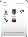
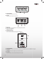
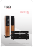
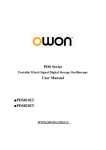
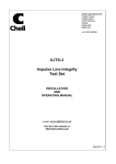
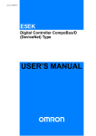
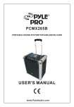
Turn it back on User Guide Urban 500 500W Output Power XLR Please read this user manual carefully before using your Urban 500 and retain for future reference. Turn it back on SAFETY Safety precautions A triangle with a lighting symbol draws the user’s attention to “dangerous voltage” without insulation in the cabinet, which may be high enough to entail a risk of an electric shock. A triangle with an exclamation mark draws the user’s attention to important instructions for use and maintenance in the accompanying manual, which should be studied and adhered to. The symbol for a CLASS II (double insulation) product. Warning: To minimise the risk of fire or electric shock, do not expose the unit to liquid or moisture. Do not open the cabinet as it contains dangerous voltages. Only qualified technicians are allowed to carry out repair and service of this system. If the plug of the power cord needs to be replaced. It is important that the replacement is identical to the plug that needs to be replaced, or that the new plug has been recommended by the manufacturer. Caution: To avoid electric shock, it is important to insert the plug correctly into the wall outlet. Important safety instructions Warning: It is important that you read and observe both the instructions in this manual and the instruction on the unit. Keep this manual for safe future reference. This unit was designed and manufactured with a view to providing maximum safety for the user. Incorrect use of the unit may cause an electric shock or fire. The protection devices built into this unit will protect the user if the procedures below are observed in connection with installation, use and repair. This unit is fully electronic and contains no parts that can be repaired by the user. Do not remove the covers. Risk of dangerous voltage. Only qualified technicians are allowed to repair the unit. Read the manual Heat After unpacking the unit, please read the manual carefully and observe all the instructions given. Do not place the unit near sources of heat such as radiators, ovens or other units that produce heat. Power supply Water and moisture. Only the power supply indicated on the rating plate must be used for this unit. If you are not sure which power supply you have, please contact your local dealer. The unit must not be placed close to water, such as bathtub, wash basin, kitchen sink or washing machine, in a damp cellar or close to a swimming pool, etc. Earthing or polarisation Cleaning If the plug cannot be inserted properly into the socket, or if the plug does not fit, the unit must not be used in your country. Unplug the unit before cleaning. Do not use liquid detergents and aerosol cleaning agents. Use a dry cloth. Ventilation The cabinet is provided with slots and openings to ensure ventilation and reliable operation and to protect the unit against overheating. Do not block or cover these openings. The openings must never be blocked, for instance by placing the unit on a bed, a sofa, a carpet or similar surface. Power cords Wiring must be organised to prevent people from stepping on the cables and to avoid pinching by objects placed on or beside them. Take special care around sockets and plug boxes and where the power cords leave the unit. Lightning Unplug the unit for additional protection during storms or when the unit is not used for prolonged periods. This will prevent damage to the unit from lightning and power surges. 2 SAFETY Turn it back on Important safety instructions Penetration of objects and liquid Never push any foreign objects through the openings into the unit, as they may touch dangerous voltage points or short-circuit parts and cause fire or an electric shock. Do not spill liquid onto the unit. Accessories Do not place the unit on unstable surfaces such as a trolley, stand, tripod, shelf or table. The unit may fall and cause serious injury to persons or damage to the unit. Use only trolley, stand, tripod, shelf or table that is very stable or provided with the unit. The unit must be installed in accordance with the manufacturer’s instructions and by means of installation equipment recommended by the manufacturer. If the unit is placed on a trolley, the trolley must be moved very carefully. Sudden stops, unnecessary force and uneven surfaces may cause the trolley to turn over. Loads Do not place heavy loads on the unit and do not step on it. The load may fall and cause serious injury to persons or damage to the unit. Damage Unplug the unit and contact qualified technicians in the following cases: A. If the power cord or the plug is damaged. B. If liquid has been spilled on the unit or objects have fallen into the unit. C. If the unit has been exposed to liquid or moisture. D. If the unit does not work properly after adhering to the instructions in the operation manual. Only the settings described in the operation manual must be made as incorrect setting may result in damage and often will make it difficult for a qualified technician to make the unit work properly again. E. If the unit has been dropped or damaged in any other way. F. When the operation of the unit changes drastically, the unit requires service. Service Do not attempt to carry out any service work by yourself. By opening or removing the cover, you will be exposed to dangerous voltage or other hazards. Any service work should be carried out by qualified technicians. Recycling If at any time in the future you need to dispose of this product please note that waste electrical products should not be disposed of with household waste. Please recycle where facilities exist. Check with your Local Authority or retailer for recycling advice. Approval This product complies with European Low Voltage and Electromagnetic Compatibility Directives when used and installed according to this instruction manual. Overloading Do not overload wall outlets or extension cords as this can result in the risk of fire or electric shock. Overloaded AC outlets, extension cords, frayed power cables, damaged or cracked wire insulation, and broken plugs are dangerous. They may result in electric shock or fire hazard. Periodically examine the power cable - if its appearance indicates damage or deteriorated receptacles have it replaced by your service technician. Heat dispersion Leave at least 10 cm of space between the top, back and sides of the unit and the wall or other components for proper ventilation. 3 Turn it back on INCLUDED IN THE BOX Accessories Included with the Urban 500 are the following accessories: 1 x User Manual 1 x Urban 500 1 x Main Plugs Turn it back on User Guide Urban 500 500W Output Power XLR Please read this user manual carefully before using your Urban 500 and retain for future reference. 1 x USB cable 1 x Virtual DJ software (with CD key) Please save your packaging as you will need this in the event of warranty/service repair or support. We are unable to carry out warranty/service if you are unable to package it correctly. The safest way to package your item in the event of warranty/service repair is in it’s original box/packaging. 4 Turn it back on M ID I IN P U T L R L IN E 1 L IN E 2 USB BT BTS Y NC 16 2 5 3 6 4 7 11 19 18 9 10 15 8 17 12 21 22 20 13 14 Use of controls or adjustments or performance of procedures other than those specified herein may result in damage to product. 1. USB INPUT Plug your USB with your music for playback and mixing features. Note: External hard disk are not supported. 2. TIME BUTTON Use this knob to choose the time mode: elapsed time, remaining time or total remaining time. 3. SINGLE BUTTON Press this button to switch between the SINGLE and CONTINUOUS play mode. The selected mode is indicated on the LCD. In SINGLE mode, after each track, the unit stops the reading. In CONTINUOUS mode, the unit reads all tracks and stops. 4. LOOP IN BUTTON This button sets the beginning of the loop. The Loop indicator on the display flashes. 5. PROG BUTTON In STOP mode, you can program several tracks (20 tracks max): - Press the STOP button to enter in the stop mode. - Press the PROG button to enter in the program mode. - Use the skip track buttons to choose the track you want to listen then press the PROG button to enter your choice. - Use one more time the skip track buttons to choose the track you want to listen then press the PROG button to enter your choice. - Repeat the operation to select all the track you want to listen. - Press the PLAY/PAUSE button to start the playback. 5 Turn it back on 6. LOOP OUT BUTTON When you press this button, you set the end point of the seamless loop and you start the loop. To finish the loop, press again this button. 7. SEARCH BUTTON You may forward and backward to navigation through one track. 8. TRACK SEARCH AND BUTTON To select the previous track and select the next track. 9. DSP/BRAKE In play mode,you push the brake button at first,and then push play/pause button,the operation changes is slowness from play to pause,push play/pause button again to cancel this feature. 10. DSP/REVERSE Push the reverse button to play your track in reverse,push the reverse button again to cancel this feature. 11. TRACK SELECT BUTTONS Press the button to switch the function of jog dial to SEARCH and PITCH BEND and SCRATCH mode, when the indicator LED is off, dial the jog for pitch bend function. If the jog is unmoved for 8 seconds, the indicator is off and the jog is for pitch bend function. when the indicator LED is on, rotary the jog wheel you can enter the scratch mode, while the indicator LED is flash, dial the jog for quick search forward and backward. 12. JOG & SHUTTLE WHEELS Shuttle: Use the dial to select the scanning direction and speed. The disc is scanned in the forward direction when the shuttle dial is turned clockwise from the neutral position, in the reverse direction when the shuttle dial is turned counterclockwise. The scanning speeds up when the shuttle dial is turned faster. Jog: In pause mode, if you turn the jog, the point at which the sound is being produced moves by a number of frames corresponding to the number of clicks. Clockwise moves the point forward; counterclockwise moves the point backward. In play mode, the jog increases or decreases the speed of the song. (Clockwise: increase, counterclockwise: decrease). 13. CUE BUTTON Pressing the CUE button during play provides a return to the position at which play was started. 14. PLAY/PAUSE BUTTON Each time you press the PLAY/PAUSE button,the operation changes from play to pause or from pause to play. 15. 10 KEYBOARD Use this button field to directly select any track. To select a two-digit track number. e.g. 12, push buttons 1 and 2 quickly in sequence. 16. DISPLAY LCD Display lndicate the Track/Numbers/Time/Remain/Pitch/Continue/Single. 17. PITCH CONTROL Use this fader to increase or decrease the speed of the track. 18. RELOOP BUTTON This button is used to start the last saved loop. To finish the loop, press the re-loop button again. 19. TRACK/FOLDER The TRACK/FOLDER search allows you to navigate through folders or tracks similarly. Turn the knob to the right to advance the selection, or turn the rotary to the left to reverse the selection. Push the knob to engage the selection. 20. PITCH BUTTON If you push this button, the adjustement of the pitch potentiometer is available. 21. PITCH BEND - BUTTON The pitch will drop while the - button is pressed and return to the original pitch when it is released. 22. PITCH BEND + BUTTON The pitch will automatically rise when the + button is pressed and return to the original pitch when it is released. 6 Turn it back on XL RO UT PU TD J MI C R L 23. XLR BALANCED XLR stereo line balanced connectors. 24. DJ MIC Plug XLR type microphone plug in here. MI C VO L CUE VO L HE AD PH ON ES 25. MIC knobs Adjust volume of the microphone corresponding to MIC number. 26. CUE LEVEL CONTROL Adjusts Cue volume. 27. HEADPHONE JACKS Use to connect for audio monitoring with headphones. Connection VO LT AG E POWE R SU PPLY POWE R SOUR CE: ~ 1 15/ 230V ,6 0/ 50 Hz POWE R CONS UM PT IO N : 5 0 WA TT S AC I N CAUTION RISK OF ELECTRIC SHOCK DO NOT OPEN 28. POWER BUTTON Press the power switch to turn the unit on. To switch the POWER off press the POWER switch again. 29. VOLTAGE Set this to the correct voltage for your location standard. 30. AC CORD Use this cable to connect the AC mains power to the unit. 7 Turn it back on MIXING Console Function 1. INPUT TOGGLE SWITCH Selects which source will be live to that channel based on what you have connected to the rear panel input section. For example on CHANNEL(1) the switches allows you to choose between USB 1 and PHONE 1/LINE 1 and MIDI mode and also on CHANNEL(2) the switches will let you choose between USB and PHONO 2/LINE 2 and MIDI mode. MI DI IN PU T L 31 R 32 LI NE 1 34 LI NE 2 US B BT BT S YN C 3. MASTER LEVEL Adjusts master level output signal. 4. CH1&CH2 GAIN CONTROL Adjusts CH1&CH2 level. 3 4 5 33 2. LED METER Indicates the master output level. 5. HIGH FADER 1-2 Adjust CH1&CH2 equalization of high frequencies. 2 6. MID FADER 1-2 Adjust CH1&CH2 equalization of mid frequencies. 6 8 7. LOW FADER 1-2 Adjust CH1&CH2 equalization of low frequencies. 9 8. BOOTH VOLUME level control for the output boot. 7 10 11 12 9. CUE/MIX/PGM CONTROL Counter clockwise you will be able to monitor the assigned cue signal.Slowly turning the control clockwise to the assigned cue signal.Slowly turning the contrlo clockwise to middle position allows you to monitor CUE MIX with PGM.Moving the control clockwise to the right allows you to monitor moving the control clockwise to the right allows you to nonitor PGM output. 10. CUE FOR CH1-2 Selects which source will be live to that channel for CH1 & CH2. 11. INPUT FADER Controls individual source levels for CH1-2 in the mix. 12. CROSSFADER Slide the CROSSFADER towards a deck to cause that deck’s track to be heard in the mix. This is an important DJ tool for blending the tracks together, moving from one track to the next, and creating a good overall mix. 31. USB MIDI Plug in the USB cable into the USB MIDI port on the rear panel.Plug the other end of the USB cable into any available USB port on your computer.It will enable you to use the unit in MIDI function. 32. INPUT Plug in the line level device such as tape deck or additional CD player here. 33. Bluetooth status LED This LED indicates the connection status of Bluetooth. When LED turned solid ON, it means Bluetooth is connected. 34. Bluetooth Sync button Press this button according to below instructions for different operation: Short press 1 sec: Turn on Bluetooth and old paired device can be connected to unit, or unit will search for new Bluetooth activated device for pairing. Press/Hold 5 sec: Turn on Bluetooth and unit will enter “Pairing Mode”, new device can be connect to unit. Press/Hold 10 sec: Turn off Bluetooth and all connection will be lost. Note: Bluetooth connection is for playback only. Mixing features is not possible to use in this mode. 8 Turn it back on VIRTUAL DJ MIDI FUNCTION 1. SHIFT When another button is pressed while pressing the [SHIFT] button a different function is called out. 2. PFL The sound of channels for which the headphones [CUE] button is pressed is output to the headphone. [SHIFT]+Press: SAMPLE RECThis function record playback music to sampler. 2 1 3. BACK Let you back from Folder Structure Panel to File System Panel. 3 4. LOOPPressing the LOOP- button halfs the set loop’s length. 4 5 6 7 9 8 $ $ 10 $ 5. LOOP+ Pressing the LOOP+ button doubles the set loop’s length. 6. FX SELECT Press the FX SELECT button to choose which effect to apply to the engaged track. [SHIFT]+Press : FX ON-Pressing the FX ON button applies the effect chosen by the FX SELECT to the currently playing/loaded track. 7. SAMPLER SELECT This button is used to select a specific sample. [SHIFT]+Press : SAMPLER ON-Pressing the SAMPLER ON button engages the sampler function on your unit. 8. HOT CUE Use the three(1-3) buttons to set cue points. [SHIFT]+Press : CUE SET-Reset a new corresponding cue point for the hot cue. 9. PARAMETER 1 Adjust the value associated with Parameter 1 of the selected effect. [SHIFT]+Press : PARAMETER 2-Adjust the value associated with Parameter 2 of the selected effect. 10. MASTER TEMPO Pressing the MASTER TEMPO button sets the tempo of the track in the corresponding channels as the dominant tempo, against which other tracks can be set. [SHIFT]+Press: SYBC-Pressing the SYNC sponding channel to the tempo of the track in the other channel. Set the MASTER TEMPO, then press the SYNC button to match the tempos. After VirtualDJ user enter interface, can see the first tab presented is the sound cord tab, here you will select your sound card and channel assignments, we will look at the basic options for using your computers internal sound card. 9 Turn it back on WARRANTY CONDITIONS URBAN equipment is covered by a 1-year warranty onparts and labour except for faders (90 days). The following rules apply from the day the equipment leaves the factory: The date on the invoice is considered to be the date the warranty begins. Only companies approved by URBAN are allowed to work on the equipment. Warranty becomes void when other service technicians open the equipment. During warranty period, defective equipment must be sent by pre-paid mail in the original box. URBAN will return the goods by pre-paid mail during the first year of warranty; thereafter the mailing cost is to be paid by the recipient. Potentiometers have a limited lifetime and are not covered by the manufacturer for more than normal use. For al service enquires, refer to your local distributor, as they are best able to help you. SPECIFICATIONS » Versatile multi-format media controller. » Loudspeaker with horn for the DJ who desires portability and multi-functionality. » Output power 500 Watts. » Bluetooth connectivity. » Midi connection compatible with PC/Mac (Virtual DJ – software included). » 2 channel mixer with 3-band EQ gain control. » Inputs: Microphone (3.5 jack/XLR). » Outputs: Headphones, 1 x RCA. » Loop and re-loop function 3 hot cues, loop adjust, sound effect, bpm, sync, loop in/out. reloop, master tempo/pitch. » LCD display with blue back-light. » Multi-color lighting effects. » Top cover, Laptop holder - included, (laptop not included). Power supply: Net Weight: Gross Weight: Dimensions (WxDxH): 100-240V, 60/50Hz 32.5 kg 35.0 kg 485 x 402 x 985 mm 10 CONTACTS Tibo Ltd. DSV House, Maidstone Road, Milton Keynes MK10 0AJ United Kingdom tel.: +44 (0) 845 2711 906 e-mail: [email protected] Proof of purchase (attach your receipt here). 11 Turn it back on Turn it back on www.tibo-electronics.com