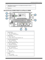
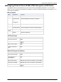
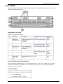
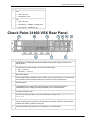
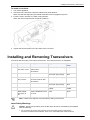
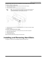
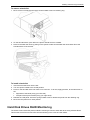
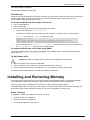
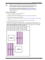
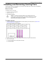
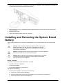
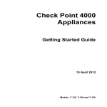
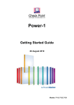
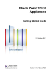
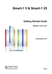
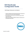
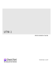
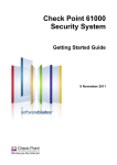
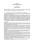
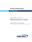
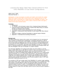
1
Check Point 21400 VSX R67.10 Getting Started Guide 24 November 2011 P/N 704712 Models: G-50 © 2011 Check Point Software Technologies Ltd. All rights reserved. This product and related documentation are protected by copyright and distributed under licensing restricting their use, copying, distribution, and decompilation. No part of this product or related documentation may be reproduced in any form or by any means without prior written authorization of Check Point. While every precaution has been taken in the preparation of this book, Check Point assumes no responsibility for errors or omissions. This publication and features described herein are subject to change without notice. RESTRICTED RIGHTS LEGEND: Use, duplication, or disclosure by the government is subject to restrictions as set forth in subparagraph (c)(1)(ii) of the Rights in Technical Data and Computer Software clause at DFARS 252.227-7013 and FAR 52.227-19. TRADEMARKS: Refer to the Copyright page (http://www.checkpoint.com/copyright.html) for a list of our trademarks. Refer to the Third Party copyright notices (http://www.checkpoint.com/3rd_party_copyright.html) for a list of relevant copyrights and third-party licenses. Important Information Latest Software We recommend that you install the most recent software release to stay up-to-date with the latest functional improvements, stability fixes, security enhancements and protection against new and evolving attacks. Latest Documentation The latest version of this document is at: http://supportcontent.checkpoint.com/documentation_download?ID=12528 For additional technical information, visit the Check Point Support Center (http://supportcenter.checkpoint.com). Revision History Date Description 24 November 2011 Added Confirming the Build Numbers (on page 14) 9 October 2011 First release of this document Feedback Check Point is engaged in a continuous effort to improve its documentation. Please help us by sending your comments (mailto:[email protected]?subject=Feedback on Check Point 21400 VSX R67.10 Getting Started Guide). Welcome Health and Safety Information Note - The Check Point Check Point 21400 VSX correlate with the following model numbers for certification purposes: G50. Read the following warnings before setting up or using the appliance. Warning - Do not block air vents. A minimum 1/2-inch clearance is required. To prevent damage to any system board, it is important to handle it with care. The following measures are generally sufficient to protect your equipment from static electricity discharge: When handling the board, to use a grounded wrist strap designed for static discharge elimination. Touch a grounded metal object before removing the board from the antistatic bag. Handle the board by its edges only. Do not touch its components, peripheral chips, memory modules or gold contacts. When handling processor chips or memory modules, avoid touching their pins or gold edge fingers. Restore the communications appliance system board and peripherals back into the antistatic bag when they are not in use or not installed in the chassis. Some circuitry on the system board can continue operating even though the power is switched off. Under no circumstances should the lithium battery cell used to power the real-time clock be allowed to short. The battery cell may heat up under these conditions and present a burn hazard. Warning - DANGER OF EXPLOSION IF BATTERY IS INCORRECTLY REPLACED. REPLACE ONLY WITH SAME OR EQUIVALENT TYPE RECOMMENDED BY THE MANUFACTURER. DISCARD USED BATTERIES ACCORDING TO THE MANUFACTURER’S INSTRUCTIONS. Disconnect the system board power supply from its power source before you connect or disconnect cables or install or remove any system board components. Failure to do this can result in personnel injury or equipment damage. Avoid short-circuiting the lithium battery; this can cause it to superheat and cause burns if touched. Do not operate the processor without a thermal solution. Damage to the processor can occur in seconds. CLASS 1 LASER PRODUCT. A TOTALLY ENCLOSED LASER SYSTEM CONTAINING A CLASS 1 LASER. For California: Perchlorate Material - special handling may apply. See http://www.dtsc.ca.gov/hazardouswaste/perchlorate The foregoing notice is provided in accordance with California Code of Regulations Title 22, Division 4.5, Chapter 33. Best Management Practices for Perchlorate Materials. This product, part, or both may include a lithium manganese dioxide battery which contains a perchlorate substance. WARNING: Handling the cord on this product will expose you to lead, a chemical known to the State of California to cause cancer, and birth defects or other reproductive harm. Wash hands after handling. Information to user: The user's manual or instruction manual for an intentional or unintentional radiator shall caution the user that changes or modifications not expressly approved by the party responsible for compliance could void the user's authority to operate the equipment. In cases where the manual is provided only in a form other than paper, such as on a computer disk or over the Internet, the information required by this section may be Health and Safety Information Page 4 Welcome included in the manual in that alternative form, provided the user can reasonably be expected to have the capability to access information in that form. Product Disposal This symbol on the product or on its packaging indicates that this product must not be disposed of with your other household waste. Instead, it is your responsibility to dispose of your waste equipment by handing it over to a designated collection point for the recycling of waste electrical and electronic equipment. The separate collection and recycling of your waste equipment at the time of disposal will help to conserve natural resources and ensure that it is recycled in a manner that protects human health and the environment. For more information about where you can drop off your waste equipment for recycling, please contact your local city office or your household waste disposal service. Health and Safety Information Page 5 Contents Important Information .............................................................................................3 Health and Safety Information ...............................................................................4 Introduction .............................................................................................................7 Welcome ............................................................................................................. 7 Overview of Check Point 21400 VSX .................................................................. 7 VSX Overview ..................................................................................................... 7 Important Solutions.............................................................................................. 8 Shipping Carton Contents.................................................................................... 8 Mounting the Appliance in a Rack .......................................................................10 Configuring Check Point 21400 VSX ...................................................................11 Powering On.......................................................................................................11 Initial Configuration .............................................................................................12 Logging in for the First Time ..........................................................................12 Configuring the Management Interface ..........................................................12 Setting Network and Time/Date Properties ....................................................13 Selecting Cluster Options ..............................................................................13 Completing the Configuration.........................................................................14 Confirming the Build Numbers ............................................................................14 Check Point 21400 VSX Front and Rear Panel ....................................................15 Check Point 21400 VSX Front Panel ..................................................................15 Check Point 21400 VSX Front Panel LEDS ...................................................16 Managing Check Point 21400 VSX Using the LCD Panel ..............................17 Line Cards .....................................................................................................18 Check Point 21400 VSX Rear Panel ..................................................................19 Customer Replaceable Parts ...............................................................................20 Installing and Removing Line Cards ...................................................................20 Installing and Removing Transceivers ................................................................21 Installing and Removing Power Supplies ............................................................22 Installing and Removing Hard Disks ...................................................................23 Hard Disk Drives RAID Monitoring .................................................................24 Installing and Removing Memory........................................................................25 Installing and Removing Cooling Fans................................................................28 Installing and Removing the System Board Battery ............................................29 Installing and Removing a LOM Card .................................................................30 VSX Appliance Recovery......................................................................................32 Registration and Support .....................................................................................33 Registration ........................................................................................................33 Support...............................................................................................................33 Where To From Here?........................................................................................33 Compliance Information .......................................................................................34 Declaration of Conformity ...................................................................................34 Chapter 1 Introduction In This Chapter Welcome Overview of Check Point 21400 VSX VSX Overview Important Solutions Shipping Carton Contents 7 7 7 8 8 Welcome Thank you for choosing Check Point 21400 VSX. We hope that you will be satisfied with this system and our support services. Check Point products provide your business with the most up to date and secure solutions available today. Check Point also delivers worldwide technical services including educational, professional and support services through a network of Authorized Training Centers, Certified Support Partners and Check Point technical support personnel to ensure that you get the most out of your security investment. For additional information on the Internet Security Product Suite and other security solutions, refer to the Check Point Web site (http://www.checkpoint.com). For additional technical information about Check Point products, consult the Check Point Support Center (http://supportcenter.checkpoint.com). Welcome to the Check Point family. We look forward to meeting all of your current and future network, application and management security needs. Overview of Check Point 21400 VSX The Check Point 21400 VSX model is ideally suited for securing medium to large data center environments and high-end enterprise networks. The Check Point 21400 VSX model is purpose-built Security Gateways in a compact 2U form factor. The Check Point 21400 VSX model is highly modular, for greater scalability and flexibility. Up to 36 I/O ports are available with the optional 12x1GbE copper and fiber (SFP) Network Interface Cards. For 10GbE network connectivity, an optional 4x10GbE fiber (SFP+) module is also available. This makes the Check Point 21400 VSX ideal for demanding network environments, and for securing many different networks. The Check Point 21400 VSX model delivers high serviceability and redundancy for components such as the hot-swappable dual power-supplies and the hot-swappable dual hard-disk drive with RAID support. Accessories include NICs, memory upgrades and a Light-Out Management (LOM) card module for out-ofband management. VSX Overview The VSX (Virtual System eXtension) appliance is a security and VPN solution, designed to meet the demands of large-scale environments. Based on the proven security of Security Gateway, VSX provides comprehensive protection for multiple networks or VLANs within complex infrastructures. It securely connects them to shared resources such as the Internet and DMZs, and allows them to safely interact with each other. VSX is supported by IPS, which provide up-to-date preemptive security. Page 7 Important Solutions VSX incorporates the same patented Stateful Inspection and Application Intelligence technologies used in the Check Point Security Gateway product line. It runs on high speed platforms (known as VSX Gateways) to deliver superior performance in high-bandwidth environments. Administrators manage VSX via a Security Management server or a Multi-Domain Security Management, delivering a unified management architecture that supports enterprises and service providers. A VSX gateway contains a complete set of virtual devices that function as physical network components, such as Security Gateways, routers, switches, interfaces, and even network cables. Centrally managed, and incorporating key network resources internally, VSX allows businesses to deploy comprehensive firewall and VPN functionality, while reducing hardware investment and improving efficiency. Key Features: Combines Virtual Firewall, VPN, and IPS Consolidates Security Gateways Onto a Single Hardware Platform Includes Virtualized Networking Components- Virtual routers, Virtual switches & Virtual cabling Wire-Speed Security for Gigabit Networks High Availability with Linear Growth Clustering Bridge Mode Support for Transparent Internal Firewalls Flexible Virtual Network Design IPS Services Updates URL Filtering This document provides: A brief overview of essential VSX concepts and features A step by step guide to getting VSX up and running Note - Screen shots in this guide may apply only to the highest model to which this guide applies. Important Solutions For more information about R67.10 VSX, go to the Check Point R67.10 VSX Home Page (http://supportcontent.checkpoint.com/solutions?id=sk65291). For a list of open issues, see the Known Limitations (http://supportcontent.checkpoint.com/solutions?id=sk65292). For a list of closed issues, see the Resolved Issues (http://supportcontent.checkpoint.com/solutions?id=sk65293). Shipping Carton Contents Item Description Check Point 21400 VSX A single VSX appliance Check Point 21400 VSX components Rack mounting accessories 1 1GbE copper line card, 12 port (for Sync, Management or Data) 2 front-facing slots for optional line cards 12 GB dynamic RAM 2 hard disk drives with RAID 2 power supplies Full complement of fans (quantity 5) Hardware mounting kit Introduction Page 8 Shipping Carton Contents Item Description Cables 2 power cords Documentation Getting Started Guide User License Agreement Introduction Page 9 Chapter 2 Mounting the Appliance in a Rack To learn how to mount the Check Point 21400 VSX in the rack, see the 21000 Appliances Rack Mounting Guide (http://supportcenter.checkpoint.com/file_download?id=12318). Page 10 Chapter 3 Configuring Check Point 21400 VSX The workflow for configuring Check Point 21400 VSX is: 1. 2. 3. 4. Mount the Check Point 21400 VSX in the rack. Connect the cables and power on. Use the First Time Wizard to configure the appliance. Configure VSX in SmartDashboard and install a policy. Note - Check Point 21400 VSX must be managed by a Security Management Server or Multi-Domain Security Management as described in the VSX NGX R67 Administration Guide (http://supportcontent.checkpoint.com/documentation_download?ID=10165). Security Management Server is not installed locally on Check Point 21400 VSX. In This Chapter Powering On Initial Configuration Confirming the Build Numbers 11 12 14 Powering On To power on Check Point 21400 VSX: 1. Connect the power cable. 2. On the rear panel, turn on the Power button to start the appliance. Note -When a power supply fails or is not connected to the outlet, an alarm sounds continuously. If you hear the alarm, replace the faulty power supply immediately, and connect the new unit to an A/C outlet. 3. After the appliance initializes and boots. The status of the appliance is displayed on the LCD screen. The appliance is ready for use when the model number is displayed. Page 11 Initial Configuration Initial Configuration Logging in for the First Time Check Point 21400 VSX includes a First Time Wizard to help you configure the initial settings for the appliance. To log in and start the First Time Wizard: 1. Connect to the appliance’s Serial console using the RJ45/D subminiature cable. 2. Connect the serial cable, RJ45/D subminiature, to the serial console port on the appliance. 3. In a terminal emulation program, configure these serial console settings: Speed: 9600 Data bits: 8 Parity: None Stop bit: 1 4. Log in for the first time using admin as the default username and password. 5. Follow the on-screen instructions and change the password. 6. Log in to expert mode. a) Enter expert. b) Enter the new admin password. c) Follow the on-screen instructions and change the expert mode password. 7. Run sysconfig to configure the appliance for the first time. The Welcome window opens. 8. Type n. The Network Configuration window opens. 9. Use the menus and windows to set the Host Name, Domain Name, and Domain Name Servers. 10. Enter n. The Network Connections window opens. Configuring the Management Interface Use the Network Configuration window to configure the parameters of the Management interface. To configure the Management interface settings: 1. In the Network Configuration window, enter 4. Configuring Check Point 21400 VSX Page 12 Initial Configuration The Network Connections window opens. 2. Enter 2. The Configure connection window opens. 3. Enter the number to select the Mgmt interface. The Choose Mgmt item to configure window opens. 4. Enter 1. The Change IP settings window opens. 5. Enter an IP address, network mask, and broadcast address for the Management interface. 6. Enter e twice to return to the Network Configuration window. 7. Enter 5. The Routing window opens. 8. Enter 1. The Set Default Gateway window opens. 9. Enter the parameters for the default gateway of the network. 10. Enter e twice to return to the Network Configuration menu. 11. Enter n. The Time and Date Configuration window opens. Setting Network and Time/Date Properties To set the system time and date: 1. 2. 3. 4. 5. In the Time and Date Configuration window, set the time zone, date, and local time. Enter n to continue. Enter n again and continue with the Check Point Configuration Program. Read the license agreement. Enter y. The Cluster Options window opens. Selecting Cluster Options You can configure the VSX appliance to work with clusters of virtual systems. To configure VSX clustering features: 1. Configure VSX clustering features. Enter y to enable and configure VSX clustering. Enter n to skip VSX clustering configuration. Skip step 2. Configuring Check Point 21400 VSX Page 13 Confirming the Build Numbers 2. Configure the Per Virtual System State. This feature is required for the Virtual System Load Sharing (VSLS). Enter y when prompted to enable this feature. If you do not intend to use these features, enter n. Note - You can use the cpconfig CLI command to change the VSX clustering settings. Completing the Configuration Complete the last steps of the First Time Wizard. The appliance reboots and is configured according to your settings. To use the VSX appliance, you must configure and install a security policy according to the VSX NGX R67 Administration Guide (http://supportcontent.checkpoint.com/documentation_download?ID=10165). To complete the First Time Wizard and reboot the appliance: 1. You can add a license. 2. Enter and confirm a SIC activation key. This key establishes SIC trust between the gateway and the management server. 3. If VSX clustering features are enabled, you can enable ClusterXL for Active/Standby Bridge Mode. 4. Enter y to reboot the appliance. Confirming the Build Numbers Confirm that the system has the most recent build numbers. Run these CLI commands to display the build number for these products. Product SecurePlatform VSX Dynamic Routing VSX Command ver VSX Appliance Build gated_ver 650000001 fw ver -k This is Check Point SecurePlatform Pro VSX NGX R67.10 Build 012. This is Check Point VPN-1 VSX NGX R67.10 build 006. kernel: NGX R67.10 - Build 006. Performance Pack sim ver -k This is Check Point Performance Pack version: NGX R67.10 - build 003. Kernel version: NGX R67.10 - Build 003. Configuring Check Point 21400 VSX Page 14 Chapter 4 Check Point 21400 VSX Front and Rear Panel This chapter describes the Check Point 21400 VSX front and rear panel In This Chapter Check Point 21400 VSX Front Panel Check Point 21400 VSX Rear Panel 15 19 Check Point 21400 VSX Front Panel Item Description 1 System LEDs (System power, system status, and hard disk activity). 2 LCD display screen. 3 Keypad for LCD screen. 4 2 Hard disk drives. When monitoring the disks using the raid_diagnostic command, DiskID 0 is the top disk, and DiskID 1 is the bottom disk. 5 Hard disk power and activity LEDs. 6 Three slots for Ethernet interface line cards. 7 Console port - for a serial connection to the appliance using a terminal emulation program such as HyperTerminal. 8 LOM (Light Out Management) port for the optional LOM card. Page 15 Check Point 21400 VSX Front Panel Item Description 9 Management connection port - for an Ethernet connection to a remote management computer. 10 USB ports. Check Point 21400 VSX Front Panel LEDS Item Description 1 System Power. 2 3 4 5 6 7 OFF - System power off ON (Green) - System power on System Status. Green – System OK Orange – Alarm for voltage, temperature or fan. Hard disk drive (HDD) Activity. OFF - No HDD Activity ON (Green) - HDD Activity Hard disk drive (HDD) Activity. OFF - No HDD Activity ON (Amber) - HDD Activity Hard disk drive (HDD) Power. OFF – HDD Power off ON (Green) – HDD Power on Link OFF - No Link ON (Green) - Link Activity OFF - No Activity Slow Blink (Amber) - Activity Check Point 21400 VSX Front and Rear Panel Page 16 Check Point 21400 VSX Front Panel Managing Check Point 21400 VSX Using the LCD Panel The appliance has an LCD panel that you can use to do basic management operations. You can enable DHCP. You can configure the management IP address, netmask, and default gateway of the appliance. You can reboot the appliance. Menu Options Menu Sub-menu Purpose Set Internal IP Set the management interface IP address Network or Set Mgmt IP Set Netmask Set the management interface network mask Set Default GW Set the management interface default gateway System Reboot Reboot the appliance LCD Panel Keys To Press Enter the main menu Enter Navigate the menu or Select a menu option Enter Go back to previous menu ESC When Entering an IP Address To Press Move to the next digit Enter Move back to the previous digit ESC Approve the change Enter when the cursor is located on the last digit Cancel the IP change ESC when the cursor is located on the first digit Change current digit or Check Point 21400 VSX Front and Rear Panel Page 17 Check Point 21400 VSX Front Panel Line Cards The Check Point 21400 VSX front panel has three slots for cold-swappable Line Cards (also known as Network interface Cards (NICs)). Supported Line Cards These Line Cards are available: Item Line Card Description 1 10GbE SFP+ Line Card, 4 Port 10 Gb Ethernet PCI-e line Fiber-optic (short range) card for SFP+ transceivers 2 1GbE SFP Line Card, 12 Port 3 1GbE Copper Line Card, 12 port 12 port 1Gb Ethernet PCI-e line card for SFP transceivers Supported Transceivers Latch Lever Color Black Fiber-optic (long range) Blue Fiber-optic (short range) Black Fiber-optic (long range) Blue Copper Yellow 12 port 1000BaseT PCI-e None line card None Line Card Slot and Port Numbering Line Card slots are numbered from 1 to 3, top to bottom. Slot 1 = top, slot 2 = middle, slot 3 = bottom. The Line Card ports are numbered from 1, left to right. For example, in a 12-port card, the slots are numbered 1 to 12, left to right. Line Card LEDs Item Description 4 Activity OFF - No Activity Slow Blink (Amber) - Activity Check Point 21400 VSX Front and Rear Panel Page 18 Check Point 21400 VSX Rear Panel Item Description 5 Link 6 OFF - No Link ON (Green) - Link Link OFF - No Link ON (Green) - 10Mbps or 1Gbps Link ON (Amber) - 100Mbps Link Check Point 21400 VSX Rear Panel Item Description 1 2 redundant, hot-swappable AC power supplies. Each power supply connects to an electric outlet. 2 LED indicator for power supply, one for each power supply: OFF — power off ON (Green) — power on. 3 Main power switch. 4 Power supply alarm suppression button. When a power supply fails or is not connected to the outlet, an alarm sounds continuously. Press here to turn off the alarm. 5 Grounding plug 6 5 replaceable CPU cooling fans, behind the grille. Each cooling fan operates independently of the others, providing redundancy in the event of failure. 7 Fan grille retaining screw 8 The fans are redundant pairs. They are numbered from right to left: 1A/B, 2A/B, 3A/B, 4A/B, 5A/B. 9 Extraction handles and retaining thumb screws for the bottom tray (that contains the system board) and the top tray (for an ADP Service module). There are also extraction handles and retaining screws on the right. 10 Accelerated Data Path (ADP) service module tray, behind the grille. Check Point 21400 VSX Front and Rear Panel Page 19 Chapter 5 Customer Replaceable Parts For maximum availability and easy maintenance, the appliance has many customer replaceable parts. Important - customers are prohibited by warranty and support agreements from changing any parts or altering the hardware in any way except as noted below, or as directed by Check Point technical support. In This Chapter Installing and Removing Line Cards Installing and Removing Transceivers Installing and Removing Power Supplies Installing and Removing Hard Disks Installing and Removing Memory Installing and Removing Cooling Fans Installing and Removing the System Board Battery Installing and Removing a LOM Card 20 21 22 23 25 28 29 30 Installing and Removing Line Cards This section presents the procedures for removing and installing Line Cards. There are three Line Card slots in the front of the appliance. Important - Make sure that you are electromagnetically grounded when performing these procedures. Static electricity can damage the appliance. To remove a Line Card: 1. Turn off the appliance. 2. Loosen the thumb screws on the two sides the Line Card. 3. Squeeze the spring-loaded section of the ejector handle in the direction of the outer edge of the Line Card, and turn the ejector out. Do this at the same time on the right and the left ejectors. 4. Holding the ejector, pull the Line Card out of the slot. Page 20 Installing and Removing Transceivers To install a Line Card: 1. Turn off the appliance 2. Insert the Line Card with the ejectors rotated out a small distance. Make sure that the alignment pins behind the thumb screws engage the top hole. 3. Push the card in until the Line Card is fully inserted. When the card is fully inserted, the ejector rotates in. 4. Tighten the thumb screws on the two sides of the Line Card. Installing and Removing Transceivers Line Cards with fiber optic ports require transceivers. The transceivers are hot swappable. Item Line Card Description 1 10GbE SFP+ Line Card, 4 Port 10 Gb Ethernet PCI-e line Fiber-optic (short range) card for SFP+ transceivers 2 3 1GbE SFP Line Card, 12 Port 1GbE Copper Line Card, 12 port 12 port 1Gb Ethernet PCI-e line card for SFP transceivers Supported Transceivers Latch Lever Color Beige Fiber-optic (long range) Blue Fiber-optic (short range) Black Fiber-optic (long range) Blue Copper Yellow 12 port 1000BaseT PCI-e None line card None Note - Check Point supports only transceivers sold by Check Point. Laser Safety Warnings Caution - When laser products (such as fiber optic devices or transmitters) are installed, note the following: Do not remove the covers. Removing the covers of the laser product could result in exposure to hazardous laser radiation. There are no serviceable parts inside the device. Customer Replaceable Parts Page 21 Installing and Removing Power Supplies CLASS 1 LASER PRODUCT. A TOTALLY ENCLOSED LASER SYSTEM CONTAINING A CLASS 1 LASER. Note - Laser radiation when open. Do not stare into the beam, do not view directly with optical instruments, and avoid direct exposure to the beam. To install a transceiver: 1. Push the transceiver into an available port in the Line Card. 2. Turn the transceiver latch lever down to secure the transceiver in the Line Card. 3. Insert a correct interface cable into the transceiver. To remove a transceiver: 1. Remove the cable. 2. Release the transceiver by rotating the latch lever. 3. Pull out the transceiver. Installing and Removing Power Supplies This section shows how to remove and install a power supply. The appliance contains two redundant, hot swappable power supplies. The two active power supplies do load sharing. Load sharing increases the life of the power supplies. Additionally, if one fails, the system continues to operate. Customer Replaceable Parts Page 22 Installing and Removing Hard Disks The power supply LEDs at the rear of the appliance show the status of the power supplies. To remove a power supply unit: 1. Loosen the retaining screw located at the top left of the power supply. 2. Unlock the power cord clip. 3. Pull the extraction handle to remove the power supply unit. Note - Use only the extraction handle to remove the power supply unit. To prevent damaging the power supply, do not pull on the retaining screw, power cord clip or any other part of the unit. 4. If the alarm sounds, press the red Alarm Off button to the right of the power supply. The alarm stops. To install a replacement power supply: 1. 2. 3. 4. Insert the power supply into its slot and push firmly until it clicks into position. Tighten the retaining screw. Insert the power cord. Lock the power cord clip. Make sure that the green power supply LED is illuminated. Installing and Removing Hard Disks The appliance contains two hot-swappable redundant hard disk drives. Customer Replaceable Parts Page 23 Installing and Removing Hard Disks To remove a hard disk 1. Move out the LCD panel and lock the spring-loaded screw into retaining ring. 2. On the hard disk drive, push left on the ejector handle and turn outward. 3. Remove the hard disk drive by pulling on the ejector handle and the hard disk drive bezel. Move the hard disk drive of the chassis. To install a hard disk: 1. Insert the hard disk drive into the slot. 2. Turn the ejector handle to the closed position. 3. Press on the hard disk drive until it sits in its connector. To do this, apply pressure, at the same time on the: Right side of the bezel (using your left hand). Flat part of the ejector handle (using your right hand). 4. Release the LCD panel: Press the spring-loaded screw to release the panel from the retaining ring. 5. Move the LCD panel to its usual position. Hard Disk Drives RAID Monitoring The Check Point 21400 VSX performs RAID1 mirroring across two hard disk drives using software RAID. This lets the Check Point 21400 VSX continues working in the event of a disk failure. Customer Replaceable Parts Page 24 Installing and Removing Memory The mirror rebuild is automatic. The two disks must be the same type. First Boot Up At first boot up, let the disk fully synchronize. After two hours, the disks are synchronized. Do not reboot the system until the disks are fully synchronized. If you reboot before the disks are synchronized, the synchronization starts again at the next boot. To monitor the RAID state of the disks from the CLI 1. Log in to the appliance 2. Enter expert mode 3. Use one of these tools to monitor the RAID status of the disks: At the command line run raid_diagnostic. This shows information about the RAID and disks, with the % progress of the synchronization. DiskID 0 is the top disk. DiskID 1 is the bottom disk. At the command line run cpstat os –f raidInfo. This shows almost the same information as the raid_diagnostic command, but in tabular format To monitor the RAID state of the disks Using SNMP To monitor the RAID status of the disks Using SNMP, set up SNMP traps to send information about the RAID. Use OID: 1.3.6.1.4.1.2620.1.6.7.7 To Hot Swap a disk: Important - Make sure that at least one fully synchronized disk is in the system. 1. When the system is up, remove the failed disk. 2. Wait 15 seconds for the system to recognize that the disk was removed. 3. Insert a new disk at this time or at a later time. You can reboot the system with one disk. The system automatically adds the new disk to the RAID configuration. Installing and Removing Memory The Check Point 21400 VSX has 12 dual inline memory-module (DIMM) sockets. This section describes how to upgrade or replace the memory by using a Check Point-approved memory upgrade kit. Only use memory kits purchased from Check Point or Check Point-approved resellers. The DIMM sockets are in two groups of four sockets. The sockets are located on the left font and right rear of the Check Point 21400 VSX system board, as you look at the appliance from the front. Before You Begin To upgrade or replace your appliance memory, you need: Physical access to the appliance Check Point memory upgrade kit Access to the appliance using the CLI Customer Replaceable Parts Page 25 Installing and Removing Memory Caution- To protect the appliance and the memory modules from electrostatic discharge damage, make sure you are properly grounded before you touch these components. Use a grounding wrist strap and follow the instructions provided with the wrist strap before you handle the components or open the appliance. The grounding plug on the rear of the appliance ("Check Point 21400 VSX Rear Panel" on page 19) provides a chassis grounding point. If you do not have a grounding wrist strap, make sure you are properly grounded before you touch any electronic component. To add or replace DIMMs: 1. Power down the appliance and remove the lower tray: a) Use the CLI to shut down the appliance. b) Press the power switch at the rear of the appliance to turn off power to the appliance. c) Remove the power cords from the appliance. d) Loosen the two retaining screws for the lower tray ("Check Point 21400 VSX Rear Panel" on page 19). e) Pull hard on the extraction handles, and fully remove the tray from the appliance. 2. Find the DIMM memory slots on the system board. The basic memory configuration of the Check Point 21400 VSX ship with six DIMMs installed. The optional memory configuration of the appliance ships with 12 DIMMs installed. Each DIMM is 2 Gbyte. When replacing a DIMM in the basic memory configuration: Use the same six slots. The DIMMs slots must always be populated as shown in the diagram. Customer Replaceable Parts Page 26 Installing and Removing Memory When performing a memory upgrade to the basic memory configuration: Install more DIMMS in all the remaining slots. The DIMMs slots must always be populated as shown in the diagram. 3. To remove a DIMM: a) Press the two retaining clips outward b) Carefully pull the DIMM up. You will possibly find it necessary to pull one end of the DIMM and then the other to gradually release it from the contact pins. 4. To insert a DIMM: Press the new DIMM into the socket until it clicks into position. The top of the DIMM is smooth. The bottom edge has two different-length sets of contacts, which connect to the slots on the socket. Be sure the contacts and slots are correctly aligned before you insert the DIMM. The retaining clips move into the lock position as you press the DIMM into position. 5. Insert the lower tray and turn on the appliance: a) Move the system board tray into the appliance until it clicks into position. b) Refasten the two retaining screws for the lower tray. c) Connect the power cords to the appliance. d) Press the power switch at the rear of the appliance, to turn on the power to the appliance. The appliance automatically recognizes the new memory configuration. 6. Make sure the configuration is correct using the CLI. Customer Replaceable Parts Page 27 Installing and Removing Cooling Fans Installing and Removing Cooling Fans The 5 CPU fan units are hot swappable. You can remove and install a fan unit at the rear of the appliance without shutting down the appliance. Before You Start: To replace a fan unit, you need: Physical access to the appliance Replacement fan unit Flat headed screwdriver Caution - Components inside the appliance can overheat if they are not cooled even for a short period of time. If you replace a failed fan unit, and do not completely remove power to the appliance, do not let the appliance run without a fan unit for longer than necessary. To replace a fan unit: 1. Find the fan grille at the rear of the appliance and the retaining screw that secures it ("Check Point 21400 VSX Rear Panel" on page 19). The fans are numbered as in the diagram. 2. Use the screwdriver to loosen the retaining thumb screw by turning it counterclockwise. 3. Remove the fan grille: a) Use your fingernail to move the grille to the right. b) Pull out the grille. Customer Replaceable Parts Page 28 Installing and Removing the System Board Battery 4. Pull the fan out to remove it. If necessary, use leverage. For example, use the flat head of a screwdriver to slowly remove the fan unit, because of the tight fit. 5. If the appliance is running, immediately install a replacement fan. Push the fan into the chassis until it locks into position. 6. Replace the fan grille. 7. Tighten the retaining thumb screw of the fan grille. Installing and Removing the System Board Battery This section describes how to change the CMOS battery on the system board of the Check Point 21400 VSX. Warning- Risk of explosion if battery is replaced by an incorrect type. Replace the battery only with the same or equivalent type that the manufacturer recommends. Dispose of used batteries according to the manufacturer's instructions. Warning- Make certain that you removed the power cord from the appliance before you proceed with any of the following steps. Caution- Make certain that you are properly grounded when you handle components internal to the appliance to protect against electrostatic discharge damage to the appliance. Before You Start: To replace a Check Point 21400 VSX battery, you need: Physical access to the appliance A replacement battery Access to the appliance by using the CLI To replace the battery: 1. Power down the appliance and remove the lower tray: a) Use the CLI to shut down the appliance. b) Press the power switch at the rear of the appliance to turn off power to the appliance. c) Remove the power cords from the appliance. Customer Replaceable Parts Page 29 Installing and Removing a LOM Card d) Loosen the two retaining screws for the lower tray ("Check Point 21400 VSX Rear Panel" on page 19). e) Pull hard on the extraction handles, and fully remove the tray from the appliance. 2. Find the small coin battery. It is in a black battery slot on the left wall of the system board tray, looking from the rear. 3. Remove the battery: a) Move aside the battery retaining clip. b) Use a small nonconducting device, such as a plastic probe, to move the battery out of the battery holder. Caution - You must place the new battery into the battery holder observing the correct polarity. The positive terminal of the battery must be facing the wall of the chassis case. 4. With the positive side facing the wall of the chassis, slide the new battery into the battery holder. Make sure that the battery is securely installed. 5. Insert the lower tray and turn on the appliance: a) Move the system board tray into the appliance until it clicks into position. b) Refasten the two retaining screws for the lower tray. c) Connect the power cords to the appliance. d) Press the power switch at the rear of the appliance, to turn on the power to the appliance. 6. Reset the appliance date and time information using the CLI. It is necessary to do this because the battery keeps the date and time when you shut down the appliance. Installing and Removing a LOM Card The Check Point 21400 VSX Lights Out Management card provides out-of-band remote access to the appliance, even when it is turned off. The Lights-Out Management card is an optional accessory. To insert or remove a LOM card 1. Power down the appliance and remove the lower tray: a) Use the CLI to shut down the appliance. b) Press the power switch at the rear of the appliance to turn off power to the appliance. c) Remove the power cords from the appliance. d) Loosen the two retaining screws for the lower tray ("Check Point 21400 VSX Rear Panel" on page 19). e) Pull hard on the extraction handles, and fully remove the tray from the appliance. 2. Find the LOM card slot (or the LOM card, if already installed). It is near the middle of the left side of the system board tray, looking from the rear. 3. To insert the LOM card: a) Hold the LOM card at a small angle to align with connector. b) Insert the LOM card into the connector. c) Press down on the LOM card until it lies flat. d) Lock the card into the socket. 4. To remove the LOM card: a) Pull the socket locking levers OUT (away from the card edge). b) Lift the back of the card up and away from system board. 5. Insert the lower tray and turn on the appliance: Customer Replaceable Parts Page 30 Installing and Removing a LOM Card a) Move the system board tray into the appliance until it clicks into position. b) Refasten the two retaining screws for the lower tray. c) Connect the power cords to the appliance. d) Press the power switch at the rear of the appliance, to turn on the power to the appliance. Customer Replaceable Parts Page 31 Chapter 6 VSX Appliance Recovery VSX comes preloaded on your Check Point 21400 VSX appliance. If, for any reason, you need to reinstall VSX on the appliance, follow this procedure. To reinstall VSX software on the appliance: 1. Connect to the appliance console using the designated cord received in your shipping carton (RJ45/Dsubminiature cable) and connect to the console using Terminal Emulation software, such as HyperTerminal or PuTTY. 2. Load the Installation CD that you received in your shipping carton into a portable USB CD-ROM/DVDROM drive. 3. Connect the portable CD-ROM/DVD-ROM drive to the appliance's USB socket. 4. Power-On your appliance. 5. Once the appliance boots from the CDROM/DVD drive, press Enter to start the installation. 6. The installation automatically installs all required components and the progress of each stage is shown. 7. When you see the message, "You may safely reboot your system," reboot the appliance manually using the master power button. Turn the appliance off and disconnect the USB CD-ROM/DVD-ROM. After several seconds, press the master power button to turn on the appliance again. To install the existing security policy and configuration on the recovered gateway or cluster members: 1. From the command line of the Security Manager server or Multi-Domain Security Management run: vsx_util reconfigure 2. Enter the following information when prompted: a) IP address of the Security Manager server or CMA that holds the VSX object b) Administrator username and password c) Gateway or Cluster member object name d) SIC activation key for the recovered gateway or cluster member 3. Reboot the reconfigured gateway or Cluster member. The VSX appliance now contains the security policy and is part of the network configuration. For more information about the vsx_util reconfigure command, see the VSX NGX R67 Administration Guide (http://supportcontent.checkpoint.com/documentation_download?ID=10165). Page 32 Chapter 7 Registration and Support In This Chapter Registration Support Where To From Here? 33 33 33 Registration Check Point 21400 VSX requires a specific Check Point license. Obtain a license and register at the Check Point Appliance Registration site (http://register.checkpoint.com/cpapp). Note - The MAC address of the management interface is required to obtain a license. Support For additional technical information about Check Point products, consult the Check Point Support Center (http://supportcenter.checkpoint.com). Where To From Here? You have now learned the basics that you need to get started. The next step is to obtain more advanced knowledge of your Check Point software. See the VSX NGX R67 Administration Guide (http://supportcontent.checkpoint.com/documentation_download?ID=10165), also available on the CD. Check Point documentation is available on the Check Point Support Center (http://supportcenter.checkpoint.com). Be sure to also use the Online Help when you are working with the Check Point SmartConsole clients. Page 33 Appendix A Compliance Information This appendix contains declaration of conformity, compliance, and related regulatory information. In This Appendix Declaration of Conformity 34 Declaration of Conformity Manufacturer’s Name: Check Point Software Technologies Ltd. Manufacturer’s Address: 5 Ha'Solelim Street, Tel Aviv 67897, Israel Declare that under our sole responsibility the products Model Number: G50 Product Options: All Serial Number: 1 to 100,000 Date First Applied: 2011 Conforms to the following Product Specifications: EMC FCC, 47 CFR, Part 15, Class A Information Technology Equipment - Radio Disturbance Characteristics VCCI V-3, Class A Information Technology Equipment - Radio Disturbance Characteristics AS/NZS CISPR22, Class A Information Technology Equipment - Radio Disturbance Characteristics ICES-003, Class A Information Technology Equipment - Radio Disturbance Characteristics CISPR22 Information Technology Equipment - Radio Disturbance Characteristics EN55022, Class A Information Technology Equipment - Radio Disturbance Characteristics EN 61000-3-2 Information Technology Equipment - Harmonics Characteristics EN61000-3-3 Information Technology Equipment - Flicker Characteristics Page 34 Declaration of Conformity Safety EN 55024 Information Technology Equipment - Immunity Characteristics EN61000-4-2 Information Technology Equipment - Electrostatic Discharge Immunity EN61000-4-3 Information Technology Equipment - Radiated RF Immunity EN61000-4-4 Information Technology Equipment - Fast Transient Immunity EN61000-4-5 Information Technology Equipment - Surge Immunity EN61000-4-6 Information Technology Equipment - Conducted RF Immunity EN61000-4-11 Information Technology Equipment - Voltage Dips and Short Interruptions Immunity CAN/CSA, C22.2 No. 60950-1-07 Safety of Information Technology Equipment UL 60950-1:2007 second edition Safety of Information Technology Equipment EN 609501:2006/A11:2009 Safety of Information Technology Equipment The product herewith complies with the requirements of the EU Directive 2006/95/EC and the EMC Directive 2004/108/EC Date and Place of issue: July, 2011, Tel Aviv, Israel FCC Notice (US) This equipment has been tested and found to comply with the limits for a Class A digital device, pursuant to part 15 of the FCC Rules. These limits are designed to provide reasonable protection against harmful interference when the equipment is operated in a commercial environment. This equipment generates, uses, and can radiate radio frequency energy and, if not installed and used in accordance with the instruction manual, may cause harmful interference to radio communications. Operation of this equipment in a residential area is likely to cause harmful interference in which case the user will be required to correct the interference at his own expense. Caution Any changes or modifications not expressly approved by the grantee of this device could void the user’s authority to operate the equipment. Compliance Information Page 35