1
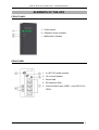
DUO II / DUO II Pro series UPS – Instruction Manual
TABLE OF CONTENTS
TABLE OF CONTENTS....................................................................................................................................... 2
INTRODUCTION ................................................................................................................................................. 3
GENERAL FEATURES OF THE UPS................................................................................................................. 3
ELEMENTS OF THE UPS.................................................................................................................................... 4
FRONT PANEL................................................................................................................................................ 4
REAR PANEL .................................................................................................................................................. 4
SAFETY AND HEALTH INSTRUCTIONS ........................................................................................................ 5
HANDLING...................................................................................................................................................... 5
ELECTRIC SAFETY........................................................................................................................................ 5
INSTALLATION................................................................................................................................................... 6
UNPACKING ................................................................................................................................................... 6
CHOOSING THE INSTALLATION SPOT ..................................................................................................... 6
CONNECTING THE UPS................................................................................................................................ 7
DESCRIPTION OF THE UPS’S OPERATION.................................................................................................... 7
SAFEGUARDS................................................................................................................................................. 9
Against overloads................................................................................................................................................... 9
Against shorting ..................................................................................................................................................... 9
Against overloads................................................................................................................................................... 9
COMMUNICATION BETWEEN THE UPS AND A COMPUTER.................................................................. 10
SOFTWARE INSTALLATION .......................................................................................................................... 10
INSTALLATION AND CONFIGURATION OF THE POWERSOFTPERSONAL SOFTWARE .............. 10
Installation on computers with Windows............................................................................................................. 10
Installation on computers with Linux/Unix ......................................................................................................... 11
Software updates .................................................................................................................................................. 12
ADDITIONAL REMARKS................................................................................................................................. 13
CUT-OUT ....................................................................................................................................................... 13
UPS AND POWER GENERATORS.............................................................................................................. 13
USING THE TELECOMMUNICATION FILTER ........................................................................................ 13
STORAGE, MAINTENANCE AND TRANSPORT...................................................................................... 14
DISPOSAL...................................................................................................................................................... 14
TECHNICAL PARAMETERS............................................................................................................................ 15
INFORMATION REGARDING REGULATIONS, WARRANTY AND SUPPORT........................................ 16
DECLARATION OF CONFORMITY ........................................................................................................... 16
WARRANTY.................................................................................................................................................. 16
2010/03/19
www.ever.eu
2
DUO II / DUO II Pro series UPS – Instruction Manual
INTRODUCTION
Thank you for purchasing the DUO II / DUO II Pro UPS. Please familiarise yourself
with this instruction manual before you begin using the device. We hope that the
purchased UPS will meet your expectations.
EVER DUO II / DUO II Pro UPSs protect the devices connected to them from mains
power losses, voltage drops and eliminate the danger of damages caused by
overvoltage in the mains.
Their main purpose of the EVER DUO II / DUO II Pro series UPSs is to protect
computers, computer peripherals and fiscal devices.
GENERAL FEATURES OF THE UPS
•
Four IEC 320 outlet sockets with emergency power supply
•
Synchronisation with the mains
•
"Cold start" – option of starting the UPS without connection to the mains
•
Acoustic signalling of low battery level
•
Microchip control of all operating parameters
•
Resistance to overloads
•
Protection against shorting
•
Telecommunication filter
•
Circuit breaker
•
Communication with a computer via USB port – only DUO II Pro UPSs.
WARNING! DUO II / DUO II Pro UPSs were not designed to work
with medical equipment, in particular life and/or health support
devices.
2010/03/19
www.ever.eu
3
DUO II / DUO II Pro series UPS – Instruction Manual
ELEMENTS OF THE UPS
FRONT PANEL
1. Power switch
2. Operation mode indicator
3. Malfunction indicator
REAR PANEL
1. 4 x IEC 320 outlet sockets
2. 10 A circuit breaker
3. Power lead
4. RJ telephone filter
5. Communication port (USB) – only DUO II Pro
UPSs.
2010/03/19
www.ever.eu
4
DUO II / DUO II Pro series UPS – Instruction Manual
SAFETY AND HEALTH INSTRUCTIONS
HANDLING
•
exercise utmost caution when handling the device;
•
do not handle heavy equipment by yourself;
•
storage and operation of the device should take place in conditions conforming to
its specification.
ELECTRIC SAFETY
•
storage and operation of the device should take place in conditions conforming to
its specification;
•
even a momentary shorting of a strong current may lead to severe burns;
•
before connecting the device to the mains inspect the condition of power leads,
plugs and sockets, as well as the condition of the device itself;
•
the device must be plugged in to a three-lead sockets (two poles and earthing)
– connecting the device to any other socket may result in electric shock;
•
A device powered via a lead with a plug has an earthing lead that carries away
the leakage current from the receivers (e.g. computer equipment) – the total
leakage current must not exceed 3.5 mA.
Users are forbidden to carry out any maintenance activities, as they may lead
to injury or death. Any repairs and replacement of batteries should be
conducted only by a qualified representative of the technical support;
•
Since the device is equipped with internal power source (batterry) the
output may provide voltage even though the device itself is not connected
to the mains;
•
The recommended operating temperature for the device is 15-25°C. Maximum
operating temperature is 40°C;
Disconnect the device from the mains before cleaning. Do not use liquid or sprayed
cleaning agents;
2010/03/19
www.ever.eu
5
DUO II / DUO II Pro series UPS – Instruction Manual
WARNING! DUO II / DUO II Pro UPSs were not designed to work with
medical equipment, in particular life and/or health support devices.
WARNING! Opening the casing may result in electric shock.
WARNING! The UPS is disconnected from the mains only when the
power lead is removed from the mains socket.
INSTALLATION
UNPACKING
After unpacking, please inspect the device for damages. If you spot any damages,
please return the UPS in its original packaging to the dealer in accordance with the
procedure described at www.ever.eu / warranty service.
WARNING! The device is delivered with its accumulator connected.
Check the contents of the packaging. The packaging should contain:
•
The UPS,
•
quick reference guide,
•
IEC 320 cables – 2 sets,
•
USB cable (only PRO models),
•
warranty card.
CHOOSING THE INSTALLATION SPOT
The battery should only be used in rooms whose dustiness, temperature and
moisture levels conform with the device's specification (see Technical parameters
table). In order to ensure correct operation of the battery, appropriate cooling
conditions must be provided. That is why the UPS should be placed at least at a 20
cm distance from other objects.
The mains socket the UPS is to be connected to should be located near the battery
(maximum distance – 1,5 m) and should be easily accessible.
WARNING! The device must not be installed in the proximity of
flammable materials!
2010/03/19
www.ever.eu
6
DUO II / DUO II Pro series UPS – Instruction Manual
CONNECTING THE UPS
Due to the type and placement of cut-outs present in the UPS the safety circuits of
the building function as one of the protection measures. This is essential to provide
the UPS with shorting protection. The UPS may only be connected to a ~230V
mains socket equipped with a grounding bolt.
WARNING! After unpacking, place the device in the chosen spot without connecting
the load (computer, monitor etc.), connect it to the mains and turn on the UPS with
the switch located on the front panel in order to charge the internal batteries. After at
least 10 h (see Table 1) the batteries will have charged and the user may continue
with the installation procedure.
Batteries’ batteries reach their full capacity after approximately a month of
mains operation mode.
Next, connect the computer or other peripherals to one of the sockets located on the
rear panel of the UPS. You can connect a total of four devices whose total power
does exceed 80% of the UPSs maximum power. Remove the plug from the mains
socket and verify the operation of the system.
After installing the software on the computer you should also verify the
communication (PRO models).
DESCRIPTION OF THE UPS’S OPERATION
It is possible to start the UPS in the battery operation mode without connection to the
mains (the connected devices are powered until input voltage returns or until the
batteries are depleted).
The UPS will indicate readiness by lighting up the LEDs and a continuous acoustic
signal and then switch on in the battery operation mode, powering the devices
connected to the output.
WARNING! Since computer monitors draw varied current upon switching on, it
may lead to problems with starting the UPS and the connected devices. In such
cases please try to start the UPS again when the mains voltage is back.
The main task of the UPS is to supply power to the devices connected to its output.
Power is supplied from the batterry in cases when the level of input voltage exceeds
the upper or lower threshold or when lack thereof is detected. The support time
2010/03/19
www.ever.eu
7
DUO II / DUO II Pro series UPS – Instruction Manual
depends on the capacity of the internal batterry and the power of devices currently
connected to the output (load).
If the parameters of the mains voltage delivered to the UPSs input are correct, the
battery will operate in the condition known as mains operation mode.
While in the mains operation mode the input voltage is conducted to its output via the
anti-overvoltage circuit.
The condition in which the UPS is supplying power from its internal batteries is
known as the battery operation mode. While in this mode, special circuits are
activated which detect extreme and unacceptable operating conditions, such as
overloads or output shortings. The final stage of depletion of the battery while in the
battery operation mode is signalled optically and acoustically (see Table 1).
Switching on the power switch is accompanied by a continuous acoustic signal
and lighting of the green and red LEDs. Next, the UPS switches to the appropriate
operation mode.
Acoustic
signalling
Optical
signalling
Table 1
Mains operation mode
Battery operation mode
Battery depleted in battery operation
mode
Shorting
Overload
UPS malfunction
Battery operation mode
Battery low
Shorting
Overload
UPS malfunction
Green LED is constantly lit
Green LED blinks every 4 seconds
Green LED blinks every second
Red LED is constantly lit
LEDs are not lit
Red LED is constantly lit
Signal every 4 seconds
Signal every second
Continuous signal
Signal every 0.5 seconds
Continuous signal
WARNING! In situations when the battery is nearing depletion the
UPS may turn off without prior warning should the load increase.
2010/03/19
www.ever.eu
8
DUO II / DUO II Pro series UPS – Instruction Manual
SAFEGUARDS
Against overloads
The overload protection circuit indicates an overload in the mains operation mode at loads
exceeding 110% of nominal power with a constantly lit up red LED and a continuous sound
signal (DUO II 350/500) or with a flashing red LED and an intermittent sound signal (DUO II
800/1000). If this condition is maintained for a longer period of time, the UPS will switch off
automatically. The greater the overload, the faster the UPS will switch off. Excessive loads
while in battery operation mode will lead to the UPS switching off.
Against shorting
Protection against shorting on the input side is provided by a circuit breaker. Additionally, the
output of the UPS in battery operation mode is protected by an electronic safeguard whose
triggering is indicated by constant light of the red LED and a continuous acoustic signal. If
the shorting at the UPSs output persists for longer that 0.5 seconds while in battery
operation mode, voltage is disconnected from outlet sockets while the UPS remains in the
signalling mode. The battery has to be turned back on manually by the user.
Against overloads
In mains operation mode with loads exceeding 110% of nominal power the battery back-up
indicated the overload status with a quick intermittent sound signal (twice a second). If this
condition persists the battery back-up will switch off automatically. The greater the overload,
the faster the back-up will switch off. In battery operation mode excessive load causes the
battery back-up to switch off.
2010/03/19
www.ever.eu
9
DUO II / DUO II Pro series UPS – Instruction Manual
COMMUNICATION BETWEEN THE UPS AND A COMPUTER
DUO II Pro battery back-ups are equipped with a USB port enabling communication
of the UPS with a computer. The device is supplied with a CD-ROM featuring the
PowerSoft programme and a USB communication cable. In order to ensure proper
operation of the system, please install the PowerSoft programme first and then
connect the battery back-up to a free USB port on your computer with the supplied
communication cable. Connecting the battery back-up to the computer with the USB
cable before PowerSoft is installed will cause the Windows system to set default
drivers, which prevents communication of the UPS with the computer. If the
software is not installed while the connection is made, then random conditions
(PNP or others) may occur, which may lead to incorrect operation of the battery
back-up.
SOFTWARE INSTALLATION
INSTALLATION AND CONFIGURATION OF THE POWERSOFTPERSONAL
SOFTWARE
Installation on computers with Windows
Before beginning the installation of PowerSoft:
•
Uninstall the current version of PowerSoft or any other control software (in
situations where the user is changing the UPS protecting the computer),
•
If the UPS will communicate with the PC via a USB cable, this cable should be
initially disconnected from the computer. The software installer will prompt the
user to connect the communication cable at the appropriate time.
In order to install PowerSoft on a computer with Windows (the list of operating
systems compatible with the application is available at www.ever.eu) just run the
software installer and follow the instructions onscreen. During the installation you will
be asked to select the model of the UPS connected to the computer on which the
software is being installed. This setting may also be changed when the application is
running.
In the case of a UPS connected to the computer via a USB cable, when the
software installation is complete, the PowerSoft Personal installer will ask the user to
connect the USB cable to the computer. The system will announce that a new device
has been found and will propose to install the drivers. Select the option to install the
drivers from a chosen location and on the next screen indicate the installation folder
2010/03/19
www.ever.eu
10
DUO II / DUO II Pro series UPS – Instruction Manual
of the PowerSoft software (usually C:\Program
Files\PowerSoft) to be
searched. Next, the operating system will located and install the appropriate driver.
In the case of Windows Vista the operating system will not initiate automatic
installation of the drivers from the hard drive. After connecting the USB cable to the
computer you will need to open the control panel from the Start Menu and select
system properties. On the device tree displayed find the USB bus branch (in most
cases it will be already expanded) and select the UPS. Update the device's driver
from it's "Properties" window by right-clicking it in the list and following the
instructions onscreen. As the driver's location you should indicate the PowerSoft
installation folder (usually C:\Program Files\PowerSoft).
To uninstall PowerSoft select the "Uninstall PowerSoft" option in Start Menu. You can
also uninstall PowerSoft from the "Add and remove programs" menu in the control
panel.
Installation on computers with Linux/Unix
The binary version of the application for Linux/Unix systems is provided in the
following formats:
CentOS, RedHat, Suse Linux, Fedora Core
For the CentOS, RedHat, Suse Linux, and Fedora Core systems the software is
provided in the form of a RPM package. The software can be installed by using any
package manage available for the system installed. If you are using the command
line the software is installed by entering the following command:
rpm –ivh powersoftpersonal-x.x.x.i386.rpm
Users working with the PowerSoft must have root privileges to install the software
and use it. After installation the application may be found in the /usr/local/PowerSoft
directory.
To uninstall the application enter the following command:
rpm –ev powersoftpersonal-x.x.x
Debian
For the Debian systems the software is provided in the form of a DEB package. The
software is installed via the following command:
dpkg –-install powersoftpersonal-x.x.x.deb
To uninstall the application enter the following command:
2010/03/19
www.ever.eu
11
DUO II / DUO II Pro series UPS – Instruction Manual
dpkg –-remove powersoft
FreeBSD
For FreeBSD systems the software is provided in the form of the default package
format designed for FreeBSD systems. The software is installed via the following
command:
pkg_add powersoftpersonal-x.x.x.tbz
To uninstall the application enter the following command:
pkg_delete powersoft
WARNING! FreeBSD systems do not support communication with
the UPS via the USB cable
Starting the software
After installation the system service is started automatically, while the control panel
application can be found at /usr/local/powersoft.
Please note that for the Polish diacritics to be correctly displayed the system locale
should be Polish.
Software updates
Windows systems
The software installer for Windows systems has a built-in automatic updater.
PowerSoft may regularly check for new software versions and notify the user when
updates are available. By default the software check for updates after user log-in.
This setting may be changed in the "Update configuration" item in the system's
programme menu.
Linux/Unix systems
In the case of Linux/Unix systems PowerSoft may be updated by downloading the
new package from www.ever.eu.
In the case of CentOS, RedHat, Suse Linux, and Fedora Core PowerSoft may be
updated by entering the following command:
rpm –Uv powersoftlite-x.x.x
In the case of Debian and FreeBSD systems we recommend uninstalling the old
version and then installing the new version of the software. Commands which enable
these operations are described in the instruction manual available at www.ever.eu.
2010/03/19
www.ever.eu
12
DUO II / DUO II Pro series UPS – Instruction Manual
ADDITIONAL REMARKS
WARNING! DUO II / DUO II Pro UPSs are designated as class C2. In
domestic environment they may interfere with reception of radio
waves so the user may be forced to implement additional
preventive measures.
WARNING! Inside the UPS there are no elements to be serviced by
the end user.
CUT-OUT
The UPS is equipped with a resettable circuit breaker. While in normal operation
mode of the UPS the breaker’s button should be pressed in. Triggering the cut-out
causes the above-mentioned button to pop out. After removing the condition that
triggered the cut-out, wait a few minutes before pressing the button back in. If the
cut-out is triggered again after the UPS is switched on, please contact technical
support.
UPS AND POWER GENERATORS
By design, the UPS tolerates mains voltage variations in the range of 190 ÷ 259V, as well as
frequency variations of ±5 Hz with relation to the nominal frequency of 50 Hz. Power
generators are characterised by variable frequency of the output voltage, which depends on
the changes in the load values. If the variations of frequency of the output voltage exceed
the allowed tolerance thresholds (ie. ±5Hz), the UPS will consider the parameters of the
input voltage to be incorrect and it will switch to battery operation mode.
USING THE TELECOMMUNICATION FILTER
In order to protect the (analogue) telephone line and connected telecommunication
devices such as modems or landline telephones, the DUO II UPSs are equipped with
an anti-overvoltage filter which safeguards the devices connected against
overvoltages in the telephone line. In order to properly utilise the built-in filter it is
necessary to connect the device to the filter socket marked as OUT with a cable with
RJ11 terminators, and connect the existing telephone line with a cable of the same
type to the other socket of the filter marked as IN.
2010/03/19
www.ever.eu
13
DUO II / DUO II Pro series UPS – Instruction Manual
WARNING! Do not connect LAN cables with RJ45 terminators
because it may interrupt the transmission.
STORAGE, MAINTENANCE AND TRANSPORT
The UPS should be stored in a cool and dry place, in operating position, with
batterries completely charged:
•
In temperature between 0°C and +30°C the batterry should be charged every 6
months;
•
In temperature between +30°C and +45°C the batterr y should be charged every 3
months.
•
In order to maintain the capacity of batterries the user should disconnect the
power lead once every 6 months in order to deplete the batterries (with load
connected) and then charge them again.
The UPS should be transported in the original packaging and in conditions
conforming to the product's specification. If the original, complete packaging is
missing, EVER Sp. z o.o. shall not be responsible for any mechanical damages that
occur in transport.
DISPOSAL
Appropriate utilisation of used up electric and electronic equipment helps to avoid
consequences resulting from the presence of dangerous materials, as well as
inappropriate disposal and processing of such equipment, which may be hazardous
to human life and the environment.
Act dated 29 July 2005 on used up electric and electronic equipment, article 22.1
items 1 and 2.
According to the regulations binding in the European Union,
a crossed rubbish bin symbol means that when a product is no
longer used it should be disposed of at a special waste pickup site.
This concerns the device itself, as well as other accessories marked
with this symbol. Do not dispose of those products together with unsorted
household waste. More information can be found at www.ever.eu / disposal.
Method of safe removal of the batteries from the appliance:
The batteries should be removed from the appliance by an authorised service outlet
or by a duly authorised electrician.
2010/03/19
www.ever.eu
14
DUO II / DUO II Pro series UPS – Instruction Manual
TECHNICAL PARAMETERS
PARAMETERS
Output power
Working environment
Operating temperature
Storage temperature
Relative humidity for operation
Relative humidity for storage
Altitude (above sea level)
Maximum length of outlet cables
Duo II 350
Duo II 500
Duo II 800
Duo II 1000
Duo II Pro 350 Duo II Pro 500 Duo II Pro 800
Duo II Pro 1000
350VA / 210W 500VA / 300W
800VA/490W
1000VA/600W
Office / industrial rooms with low level of pollution
+10 ÷ +35 °C
0 ÷ +45 °C
20 ÷ 80 % (without condensation)
20 ÷ 95 % (without condensation)
up to 1000 m
< 10 m
MAINS OPERATION MODE
Input voltage
Frequency of input voltage
Range of output voltage
Switching thresholds: Mains-UPS
Shape of output voltage
Filtering of output voltage
Time to switch to battery operation mode
~190 ÷ 259 V ± 5 %
45 ÷ 55 Hz ± 1 Hz
~190 ÷ 259 V ± 5 %
~190 / 259 V ± 5 %
Same as input
LC
<6ms
BATTERY OPERATION MODE
Output voltage
(effective value)
Shape of output voltage
Switching thresholds: UPS-mains
Frequency of output voltage
Shorting safeguard
Overload protection
Batterry
Maximum charging time
Support time 100%/80%/50%Pmax
~230 V ±10 %
Modulated sinus
~200 / 249 V ± 5 %
50 Hz ±1Hz
Electronic
Electronic
1 x 12V / 5Ah
1 x 12V / 7 Ah
2 x 12V / 5Ah
2 x 12V / 7Ah
16 h
10 h
3/6/10 min
4/5.5/12 min
4/6/13 min
3/4/12 min
MECHANICAL PARAMETERS
Dimensions (h x w x d)
Weight
192 x 85 x 253 mm
2.8 kg
3.7 kg
258 x 84 x 358 mm
6.1 kg
7.6 kg
EQUIPMENT
Number of outlet sockets
Signalling
Cut-out
Telecommunication filter
Communication interface
4 x IEC 320
acoustic and visual
Circuit breaker
+
USB (only DUO II Pro)
Note: The manufacturer reserves the right to change the abovementioned parameters without notice.
2010/03/19
www.ever.eu
15
DUO II / DUO II Pro series UPS – Instruction Manual
INFORMATION REGARDING REGULATIONS, WARRANTY
AND SUPPORT
DECLARATION OF CONFORMITY
Manufactured in People's Republic of China. The UPSs structure conforms to the
appropriate subject matter standards.
WARRANTY
A separate document attached to the product constitutes the warranty. The
document must meet all formal requirements (e.g. the fields: serial number,
model/type, date of sale, and dealer stamp must be filled out). An unfilled warranty
card or lack thereof qualifies the device for a paid repair.
The manufacturer made all efforts to ensure that products offered are free of material
and workmanship defects throughout the term specified in the warranty document.
The company's liability under the warranty is limited to repairs or replacement of
products with such defects. The manufacturer shall make the decision as to how the
defect is removed. The warranty does not cover devices with mechanical damages
that occurred as a result of negligence of incorrect use nor devices subjected to any
modifications made by the user.
Apart from the arrangements included in the warranty card EVER Sp. z o.o. shall not
be liable for direct, indirect, specific, incidental or consequential losses incurred in the
course of using the UPS, even in cases when the buyer was warned about such
losses being a possibility. The company shall not be liable for any costs, such as loss
of profit or revenue, cost of equipment, costs of equipment use, costs of software,
data, replacement products, claims of third parties or other costs.
2010/03/19
www.ever.eu
16