1
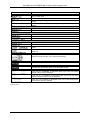
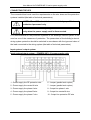
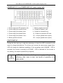
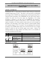
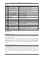
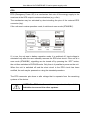
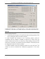
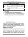
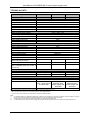
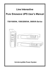
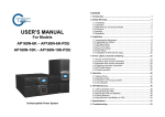
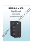
User Manual for POWERLINE 31 series power supply units
TABLE OF CONTENTS
TABLE OF CONTENTS .......................................................................................................................... 2
INTRODUCTION ..................................................................................................................................... 3
GENERAL INFORMATION ..................................................................................................................... 3
INTENDED APPLICATION OF THE POWER SUPPLY UNIT ........................................................... 3
GENERAL DESCRIPTION OF THE POWER SUPPLY UNIT............................................................ 3
UPS STRUCTURE .................................................................................................................................. 4
FRONT PANEL ................................................................................................................................... 4
BACK PANEL...................................................................................................................................... 6
INDUSTRIAL WORK SAFETY INSTRUCTIONS.................................................................................... 7
TRANSPORT ...................................................................................................................................... 7
ELECTRICAL SAFETY ....................................................................................................................... 8
INSTALLATION ....................................................................................................................................... 9
UNPACKING ....................................................................................................................................... 9
ASSEMBLY ....................................................................................................................................... 10
CONNECTING THE UPS ................................................................................................................. 11
FIRST START-UP ............................................................................................................................. 12
DESCRIPTION OF THE OPERATION OF THE POWER SUPPLY UNIT............................................ 13
GENERAL INFORMATION............................................................................................................... 13
BYPASS MODE (MODE “01”)............................................................................................................... 14
MAINS OPERATION MODE (MODE “02”) ........................................................................................... 14
BACKUP (BATTERY) MODE (MODE “03”) .......................................................................................... 15
STORAGE CELLS TEST MODE (MODE “04”)..................................................................................... 15
SERVICE BYPASS MODE.................................................................................................................... 16
EMERGENCY MODE............................................................................................................................ 16
PROTECTION................................................................................................................................... 17
Overload protection ............................................................................................................................... 17
Short circuit protection........................................................................................................................... 17
EPO ....................................................................................................................................................... 18
WORK WITH COMPUTERS ................................................................................................................. 19
RS 232 COMMUNICATION .............................................................................................................. 19
WINPOWER SOFTWARE INSTALLATION ..................................................................................... 19
CONFIGURATION OF THE UPS PARAMETERS ........................................................................... 19
POWERSOFT PERSONAL SOFTWARE INSTALLATION AND CONFIGURATION ...................... 20
Windows ................................................................................................................................................ 20
Linus/Unix .............................................................................................................................................. 21
Software update .................................................................................................................................... 22
COMMENTS ON OPERATION ............................................................................................................. 23
WORK WITH POWER GENERATORS ............................................................................................ 23
STORAGE, MAINTENANCE, AND TRANSPORT ........................................................................... 24
UTILISATION .................................................................................................................................... 24
TECHNICAL PARAMETERS ................................................................................................................ 25
INSTALLATION GUIDELINES.......................................................................................................... 25
TECHNICAL DATA ........................................................................................................................... 26
DIAGNOSTIC OPERATIONS FOR ERRORS REPORTED BY THE UPS........................................... 27
LEGAL REGULATIONS AND THE GUARANTEE................................................................................ 28
DECLARATION OF CONFORMITY ................................................................................................. 28
GUARANTEE .................................................................................................................................... 28
2010/01/25
www.ever.eu
2
User Manual for POWERLINE 31 series power supply units
INTRODUCTION
Thank you for purchasing the EVER POWERLINE power supply unit. It is the
latest series of a state-of-the-art power supply units that are dedicated to servers,
computer networks and data processing systems.
UPS EVER POWERLINE has been designed to meet all of your expectations related
to protection against power outages in the best way.
This manual contains information on how to operate and maintain the unit safely.
Thoroughly familiarise yourself with the EVER POWERLINE manual before first use
to ensure that it is operated properly.
GENERAL INFORMATION
INTENDED APPLICATION OF THE POWER SUPPLY UNIT
POWERLINE units are on-line (VFI) devices that are intended to work with
equipment powered from a ~230V single-phase grid.
NOTE! POWERLINE power supply units are not intended for use
with medical equipment to support life and/or health.
GENERAL DESCRIPTION OF THE POWER SUPPLY UNIT
POWERLINE power supply units have he following components:
•
rectifiers with PFC (power factor correction),
•
battery charger,
•
battery set,
•
inverter manufactured with high-frequency IGBT technology,
•
automatic bypass,
•
manual (service mode) bypass,
•
microprocessor control system with measurement circuits.
The input rectifies transforms the alternating voltage energy and supplies energy to
the internal DC bus. The power factor correction (PFC) system used in the unit
enables radical reduction in interference introduce to the power network. The DC bus
is the basic power source for the inverter that generates alternating sine wave current
that is used to feed the receivers. An independent charger is responsible for battery
charging. It is characterised by very low alternating charging current component
2010/01/25
www.ever.eu
3
User Manual for POWERLINE 31 series power supply units
which significantly extends battery life. A microprocessor control system (DSP)
ensures precision and reliability of the entire power supply system.
An automated bypass system increases the overall system security. In the event of
inverter failure, the current from the mains is provided directly to the load. The
automated bypass system thus becomes an additional passive safeguard of the load.
An additional manual bypass connection enables the complete switch of the load to
the mains and in consequence service and maintenance works. Internal power
circuits (except for the protected manual system) may be activated via an input fuse.
UPS STRUCTURE
FRONT PANEL
No.
Symbol
Name
1
SELECT
2
ENTER
3
OFF
4
ON
5
2010/01/25
-
LCD
Description
If the unit is in BYPASS mode or zero mode (STANDBY),
pressing this button allows you to configure the unit’s
parameters: output voltage, frequency, BYBASS mode
options. To approve the selection, press ENTER (2)
If the unit is in BYPASS mode, parameters set by means of
the SELECT key may be approved by pressing ENTER.
When the power supply is regular, pressing the OFF button
causes the unit to switch to BYPASS mode and turns off the
inverter. If the BYPASS mode option is available, the outlet is
powered from the BYPASS line
Turns the unit on
Deactivates sound alarms.
LCD
www.ever.eu
4
User Manual for POWERLINE 31 series power supply units
Display
Input*
Description
Input voltage value
Input voltage frequency
Indicates excessively high input voltage; not displayed if the voltage is
regular
Indicates excessively low input voltage; not displayed if the voltage is
regular
Output
Output voltage value
Output voltage frequency
Load
Unit load in W or VA
Indicates short-circuit of the unit’s output
Indicates unit overload
Storage cells
Storage cells voltage value
Charge level of storage cells
Indicates overload of the storage cells; the unit will switch to battery
mode
Indicates that the storage cells are discharged; the unit will soon
switch off
Mode/Error/Warning
Displays the unit’s mode, error codes and warnings
Inverter
Indicates the operational status of the inverter
Bypass
Indicates the operational status of the BYPASS circuits
Output voltage, frequency, BYPASS mode option
If the unit is in STANDBY or BYPASS mode, one of the four output
voltage values may be selected
If the unit is in STANDBY or BYPASS mode, one of the two input
voltage frequency values may be selected
If the unit is in STANDBY or BYPASS mode, one of the two BYPASS
mode options may be selected
*
For POWERLINE 10-31 power supply units, the information applies to phase C and for POWERLINE 15-31 power supply units the information
applies to phase A.
2010/01/25
www.ever.eu
5
User Manual for POWERLINE 31 series power supply units
BACK PANEL
Back panel view for POWERLINE 10-31 and POWERLINE 15-31/20-31 power
supply units
1 - Wire holders
2 - Power network and receiving terminal panel shield
3 - Input protection
4 - Parallel port (option)
5 - Adapter card (option)
6 - RS 232 communication port
7 - Fans
8 - Service BYPASS switch shield
9 - Battery pack socket
10 - EPO connector
2010/01/25
www.ever.eu
6
User Manual for POWERLINE 31 series power supply units
INDUSTRIAL WORK SAFETY INSTRUCTIONS
TRANSPORT
•
Due to the considerable weight of the device, it is necessary to exercise
particular care when transporting it;
•
The UPS units must be transported in a vertical position;
•
The equipment must be protected against atmospheric conditions (shielded
against rain);
•
Transport or storage in temperatures lower than 0°C and higher than 25°C for
extended periods is inadvisable, as it may impair the life of the batteries and
facilitate the condensation of water vapour;
•
The considerable weight and overall dimensions of the equipment make it
necessary to ensure the appropriate transport conditions (the requisite number
of people, a forklift truck, and transport corridor);
NOTE! Should you observe any damage that may impact the
correct functioning of the equipment, please contact the
Service Centre.
•
Heavy appliances must be moved by at least two or more persons;
•
The device should be operated and stored in conditions concordant with those
set in the device specification;
NOTE! POWERLINE UPS units may be transported, installed,
and maintained only by qualified personnel.
NOTE! Exercise particular care during the transport, unloading
and installation of the equipment
2010/01/25
www.ever.eu
7
User Manual for POWERLINE 31 series power supply units
ELECTRICAL SAFETY
•
it is forbidden to work on your own under conditions constituting a threat to life
and/or health;
•
in the event of a brief short-circuit, the high current may cause serious burns;
•
before connecting the device, it is necessary to check the technical condition of
the cables, plugs and sockets, as well as that of the device itself;
•
to reduce the risk of electric shock, when it is impossible to check the earthing,
the device should be disconnected from the mains before installation or
connection to other equipment and then the power supply cord should be
connected again after all the connections are made;
•
if possible, only use one hand when connecting and disconnecting the signal
transmitting cables in order to avoid potential electric shock when two surfaces
of the opposite charge touch;
•
the device must be plugged with the system containing a protective line. Failure
to comply with this requirement can lead to electric shock;
•
the installation must enable the total disconnection of the power source from the
UPS unit, for example by switching the fuse type “S”;
•
a current receiver must be connected with the appropriate circuit protection
(manual or automatic fuse);
•
the device is fitted with the earth conductor that channels leak current from
receivers (e.g. computer hardware); Differential protection should take this
aspect into account;
NOTE! The receiving line of the emergency supply system
should be equipped with a (remotely) controlled safety cut-out
(EPO - Emergency Power Off) located near the main power
switch and marked properly.
NOTE! It is strictly forbidden for the user to perform any repair
work, as this would constitute a threat to health and/or life. All
repairs
and
battery replacements
must
be
carried
out
exclusively by qualified service personnel.
2010/01/25
www.ever.eu
8
User Manual for POWERLINE 31 series power supply units
NOTE! The UPS is completely disconnected from the power
network only when the power supply cord is disconnected.
NOTE! The device is equipped with a power source (external
batteries). The device’s output may be live, even if the mains is
disconnected from the network.
NOTE! POWERLINE power supply units are not intended for
use with medical equipment to support life and/or health.
INSTALLATION
NOTE! Before installing the UPS, you must acquaint yourself
with the principles of industrial work safety as set forward in
the previous chapter.
UNPACKING
Inspect the power supply unit visually immediately upon its delivery. Although the
product is solidly packaged, the appliance could have been damaged due to shocks
experienced during transport. If any damage is discovered, inform the carrier or
seller.
The power supply unit is packed in a way that ensures safe transport (including
transport by a forklift). To unpack the device, it is necessary to:
•
carefully cut the affixing bands;
•
lift the released cardboard shield;
•
remove the foam transport protection;
•
the power supply unit should be removed from a wooden transport pallet and
placed on the floor following Health and Safety instructions (assistance of
several people might be necessary);
•
the power supply unit should be placed at the point of installation using
transport wheels;
•
the transport wheels should be blocked.
Save the packaging for future transport.
2010/01/25
www.ever.eu
9
User Manual for POWERLINE 31 series power supply units
Check the contents of the packaging. The packaging should contain the following:
•
power supply unit,
•
1 RS 232 communication cable,
•
user manual,
•
warranty card.
ASSEMBLY
•
When selecting the place of installation, consider the weight of the device:
NOTE! The user is responsible for selecting the place of
installation and ensuring the appropriate operating conditions
for the equipment.
•
It is recommended to install the UPS unit in a separate room (due to the fact
that the unit emits a uniform sound during operation, and also because such a
location provides protection against access by unauthorised persons);
•
The equipment should not be exposed to extremes of temperature (the optimal
temperature is 18 ÷ 25ºC) due to the fact that this may shorten the life of
batteries;
•
The equipment should not be installed in rooms that are: dusty, have a caustic
or explosive atmosphere, or are very humid (under 90% without condensation);
•
If the equipment is to be installed on a roof, the load bearing capacity of the roof
should be taken into consideration;
•
The surface on which the equipment is placed cannot give in under its weight;
•
Appropriate cooling conditions must be ensured for the UPS to work properly.
For this reason, the ventilation openings of the UPS must be uncovered at all
times;
•
It is recommended to leave service access to the equipment (1 m).
For the necessary data, see the table of technical parameters.
NOTE! It is forbidden to install the device near flammable
materials!
2010/01/25
www.ever.eu
10
User Manual for POWERLINE 31 series power supply units
CONNECTING THE UPS
The connected load must meet the requirements on the wire sizes and the protection
systems installed (the table of technical parameters).
NOTE! The UPS should be connected by qualified and
authorised personnel only.
NOTE! The UPS is completely disconnected from the mains
only when the power supply cord is disconnected.
It is recommended for the protection systems in the building's electric system to be
used as one of the measures of protection. The parameters of the building's electric
wiring system protection should be selected in accordance with the type and value of
the load connected to the wiring system (the table of technical parameters).
Input system / output system
Input system/output system – POWERLINE 1-31 power supply units
1 - Power supply line PE protection wire
6 - Jumper (parallel work option)
2 - Power supply line neutral N wire
7 - Jumper (parallel work option)
3 - Power supply line phase A wire
8 - Output line phase L wire
4 - Power supply line phase B wire
9 - Output line neutral N wire
5 - Power supply line phase C wire
10 - Output line protection PE wire
2010/01/25
www.ever.eu
11
User Manual for POWERLINE 31 series power supply units
POWERLINE 15-31 and POWERLINE 20-31 power supply units
1 - Power supply line PE protection wire
7 - Battery negative terminal
2 - Power supply line neutral N wire
8 - Output line phase L wire
3 - Power supply line phase A wire
9 - Output line neutral N wire
4 - Power supply line phase B wire
10 - Output line protection PE wire
5 - Power supply line phase C wire
JP1 - Jumper (parallel work option)
6 - Battery positive terminal
JP2 - Jumper (parallel work option)
FIRST START-UP
During the first start-up, it might be necessary to leave the UPS connected to the
mains to charge the batteries. To do that, just connect the input power supply lines.
UPS will charge the batteries regardless of the operating mode (ONLINE - UPS is
activated, the inverter is working or OFFLINE – UPS is switched off, the inverter is
not working, the output is powered by a bypass).
NOTE! The batteries of the power supply unit gain full
efficiency after, more or less, one month of operation in a
mains mode.
2010/01/25
www.ever.eu
12
User Manual for POWERLINE 31 series power supply units
DESCRIPTION OF THE OPERATION OF THE POWER
SUPPLY UNIT
GENERAL INFORMATION
POWERLINE UPS is a state-of-the-art electronic device forming an autonomous
sinusoidal voltage source of 230 V. This device is from the group of uninterrupted
power supply units of ONLINE class characterised by continuous processing. Due to
continuous power processing in the POWERLINE unit, the UPS may be used to
condition the power from the power supply line. Regardless of the voltage
fluctuations or distortion of the input flow, the POWERLINE UPS maintains a
sinusoidal waveform at output at a fixed value of ~230 V at all times. The power
supply unit operates in the mains operation mode (it does not use the energy from
the batter) in the wide range of input voltage ~304÷478 V (phase-to-phase voltage)
and it supplies voltage of ~230 V to receivers. The next advantage of the continuous
processing in the ONLINE power supply units is the fact that there are no outages
required to switch the load into another supply source (mains - battery). The
switching between the mains operation and battery mode is not noticeable for
receivers connected to the UPS output.
Code
00
01
02
03
04
Operational status
Zero mode (STANDBY)
BYPASS mode
Mains operation mode
Charge level of storage
Battery
cells at 0~20%
operation
Charge level of storage
mode
cells at 21~100%
Storage cells test mode
Signals
None
A single sound signal every 2 minutes.
None
A single sound signal every 1 second.
A single sound signal every 4 seconds.
None
ZERO MODE (“00” MODE)
2010/01/25
www.ever.eu
13
User Manual for POWERLINE 31 series power supply units
The display presents information on the battery charge status and input parameters
(the value and frequency of input voltage). The UPS does not supply voltage to the
output.
BYPASS MODE (“01” MODE)
The power supply unit switches to the BYPASS mode when the inverter is
overloaded, maximum permitted temperature is exceeded, inverter damage is
detected and when the device is switched off using the “OFF” button on the device
panel. Voltage is supplied to the output in the BYPASS mode directly from the input
line by a mechanical switch (converter). If the UPS switches to the BYPASS mode
due to an overloaded inverter or exceeding the maximum permitted temperature,
then the device itself checks the load level and the temperature of the inverter. When
these values return to the standard, the inverter reactivates. In BYPASS mode, the
unit does not provide any protection against voltage decay. Voltage from the input
line is switched to the unit’s output through an internal filter.
MAINS OPERATION MODE (MODE “02”)
2010/01/25
www.ever.eu
14
User Manual for POWERLINE 31 series power supply units
After connecting the UPS to the mains, the output voltage is generated. Power is
supplied to the output by an internal BYPASS system. When the device is connected
to the mains, the UPS batteries are also charged. The UPS is activated only after the
“ON” button on the front panel is pressed for approx. 1 second. After the completion
of a self test, the UPS is ready to work. If the mains voltage is irregular (excessively
low or high voltage, frequency outside the operating range), the unit will switch to
battery mode. If the voltage is regular, the UPS activates the inverter and it is then
ready to work.
In the mains operation mode there is voltage at the UPS output.
NOTE! When the UPS is switched off by pressing the “OFF”
button on the panel, voltage is not disconnected from the UPS
output.
Voltage
at
output
disappears
only
after
the
disconnection of the input power supply line.
BACKUP (BATTERY) MODE (MODE “03”)
In the backup mode, the sinusoidal output voltage is generated from the battery until
the mains voltage returns, the battery is discharged, or an emergency.
In the event of no mains voltage, the unit is activated in the same way as in mains
operation mode; however, the difference is that following the completion of self test
the panel displays the battery mode screen.
STORAGE CELLS TEST MODE (“04” MODE)
When in the storage cells test mode, the LCD panel displays the same information as
in the battery operating mode. This mode has the “04” code. In this mode, the
excessively low or excessively high input voltage indicators are not available.
The storage cells test mode is activate for approx. 10 seconds by pressing the “ON”
button when the UPS is in mains operation mode (“02” MODE).
2010/01/25
www.ever.eu
15
User Manual for POWERLINE 31 series power supply units
SERVICE BYPASS MODE
This mode enables UPS service without the necessity to disconnect the power supply
from the receivers connected to the UPS output.
NOTE! In the service BYPASS mode, receivers powered from
the UPS output are not protected against voltage decays in the
power supply line. In this mode, the UPS is completely shut off
from the output.
EMERGENCY MODE
In this mode, the unit sends the appropriate error codes to the LCD panel and emits
sound signals as per the following table.
2010/01/25
www.ever.eu
16
User Manual for POWERLINE 31 series power supply units
Table 1
Code Unit operational status
01
02
03
Signals
Overload in mains mode; the
A double sound signal every 1 second.
UPS is in BYPASS mode
Overload in mains mode; the
A double sound signal every 1 second.
inverter continues to operate
Overload in battery mode; early
A double sound signal every 1 second.
warning
05
Incorrect DC bus voltage
Continuous sound signal
06
Incorrect inverter operation
Continuous sound signal
07
Overload in battery mode;
output cut-off
Continuous sound signal
08
Maximum temperature
exceeded
Continuous sound signal
09
Output short circuit
Continuous sound signal
10
Incorrect communication*
Continuous sound signal
11
Disconnected battery circuit
Continuous sound signal
12
Damaged inverter relay
Continuous sound signal
14
Damaged battery thyristor
Continuous sound signal
15
Parallel operation errors
Continuous sound signal
22
Incorrect fan operation
A single sound signal every 1 second.
23
Damaged batteries and loader
A single sound signal every 1 second.
*For code 10 only a frame with error code is displayed. Other parameters are not visible.
PROTECTION
OVERLOAD PROTECTION
An overload condition is signalled by the relevant code on the LCD panel and a
sound signal (cf. Table 1).
If the load is 105-130% of the maximum load, the UPS switches to the BYPASS
mode after 10 minutes. If the load is greater than 130%, the UPS switches to
BYPASS mode after one second and cuts the power supply to the output off after 1
minute.
SHORT CIRCUIT PROTECTION
The unit signals a short circuit by means of the relevant code on the LCD panel and a
sound signal. If there is a short circuit, the power supply to the output is cut off. If the
UPS is switched off during a short circuit indication, and the short circuit is not
removed, the UPS switches to BYPASS mode, which activates the input automatic
fuses.
2010/01/25
www.ever.eu
17
User Manual for POWERLINE 31 series power supply units
EPO
EPO (Emergency Power Off) is a mechanism that cuts off the energy supply to the
receivers at the UPS output in extreme situations (e.g. a fire).
The mechanism may be activated by short-circuiting the pins of the external EPO
connector (trip).
If the unit was in mains operation mode, it switches to zero mode (STANDBY).
If, in turn, the unit was in battery operation mode, it is switched off. Input voltage is
reinstated only after the user manually removes the EPO short circuit. If the unit is in
zero mode (STANDBY), signalling can be turned off by pressing the “OFF” button;
the unit then switches to BYPASS mode. Only then is it possible to power on the unit
When the unit is switched off and the short circuit in the EPO circuit has been
rectified, the unit may be powered on using the standard procedure.
The EPO connector pins have a safe voltage that is separate from the remaining
systems of the device.
NOTE! The EPO circuit must be a separate circuit, and it is
forbidden to connect it to other systems.
2010/01/25
www.ever.eu
18
User Manual for POWERLINE 31 series power supply units
WORK WITH COMPUTERS
RS 232 COMMUNICATION
POWERLINE series units are equipped with extended management functions. There
is an RS 232 communication port or an optional Ethernet port (for UPS units with the
SNMP card). To ensure correct communication, it is necessary to connect the unit to
a free computer port by using a provided communication cable. Once connected, the
UPS and computer should be switched on and the software should be installed as
per the enclosed manual and following the installation application's instructions
(applies to Microsoft Windows).
POWERLINE unit, which may be managed and monitored in Windows via WinPower
software.
WINPOWER SOFTWARE INSTALLATION
During installation, please follow the application installer instructions (version for MS
Windows), when the programme asks for a series number, please enter:
511C1 -01220-0100-478DF2A
CONFIGURATION OF THE UPS PARAMETERS
The user can change certain parameters of the UPS unit by using WinPower
software. To make this possible, the UPS must be connected to a computer by the
cable provided by the manufacturer and the user must be logged in as the
administrator. By default, the administrator’s password is set to “Administrator”. After
logging in, the user may change the password.
The parameters that can be modified by the user by the software are shown in the
screenshot below. The range of the input frequency for BYPASS, the range of
voltage for BYPASS, settings of the function of the panel buttons, and sound alarms
and device response when it is switched off.
2010/01/25
www.ever.eu
19
User Manual for POWERLINE 31 series power supply units
POWERSOFT PERSONAL SOFTWARE INSTALLATION AND CONFIGURATION
WINDOWS
Before installing PowerSoft:
•
uninstall any previous version of PowerSoft and other monitoring software (if the
user is exchanging a UPS for the same computer);
To install PowerSoft with Windows (a list of operating systems verified for
compatibility with the software is available at www.ever.eu), simply launch the
software installer and then follow the instructions. When installing, choose the UPS
model that is connected to the computer running the software. That setting can also
be changed later when the software is installed.
To uninstall PowerSoft, select the PowerSoft uninstall icon in the start menu. The
software can also be uninstalled from “Add/remove programmes”, in the control
panel.
2010/01/25
www.ever.eu
20
User Manual for POWERLINE 31 series power supply units
LINUS/UNIX
The binary version for Linux/Unix is provided in the following forms:
CentOS, RedHat, Suse Linux, and Fedora Core
For systems: CentOS, RedHat, Suse Linux, and Fedora Core, the software is
supplied as an RPM package. The software can be installed using any package
manager in the operating system. If using the command line, the software is installed
by typing:
rpm -ivh powersoftpersonal-x.x.x.i3 86.rpm
The user must have administrator privileges (root) to install and use the software.
Once installed, the application is in
/usr/local/powersoft.
To uninstall, type in the command line:
rpm –ev powersoftpersonal-x.x.x
Debian
For Debian system, the software is provided as a DEB package. The software is
installed by typing in the command line:
dpkg --install powersoftpersonal-x.x.x.deb
To uninstall, type in the command line:
dpkg --remove powersoft
FreeBSD
For FreeBSD systems, software is provided as the default package for FreeBSD
systems. The software is installed by typing in the command line:
pkg_add powersoftpersonal-x.x.x.tbz
To uninstall, type in the command line:
pkg_delete powersoft
2010/01/25
www.ever.eu
21
User Manual for POWERLINE 31 series power supply units
Initialisation
Once installed, the system service is initialised automatically, while the control panel
application is at /usr/local/powersoft. Make sure that the system localisation
is Polish to enable Polish diacritical symbols.
SOFTWARE UPDATE
Windows
The installer application for Windows features an embedded automatic software
updater. PowerSoft can check regularly for new versions and notify the user about
their availability. By default, the available updates are verified after the user logs in.
That setting can be changed in the “Update configuration”, in the programmes menu
in the system.
Linux/Unix
PowerSoft for Linux/Unix can be updated using new versions available at
www.ever.eu. In case of CentOS, RedHat, Suse Linux, and Fedora Core, the update
can be executed by typing:
rpm –Uv powersoftlite-x.x.x
In Debian and FreeBSD, it is recommended to uninstall the older version and then
install the new one. Instructions for the above operations are provided in the software
manual available at www.ever.eu.
2010/01/25
www.ever.eu
22
User Manual for POWERLINE 31 series power supply units
COMMENTS ON OPERATION
NOTE! This product is intended for commercial and industrial
use in the second environment. To prevent interference
emissions, it may be necessary to apply additional measures of
prevention or the limitation of the system.
NOTE! The battery module contains no end-user serviceable
elements.
•
Damage to the guarantee seal in turn results in the automatic voidance of the
device’s guarantee.
•
All repairs should be performed solely by qualified service personnel.
•
The unit may operate below expectations, if the receiver device requires high
impulse power. In practice, even if the average power of the receiver device is
within the permitted level of the UPS, the device can turn the UPS off. This
results from the high instantaneous power collected by the device, much above
the power rating of the UPS and leading to an overload and UPS shut down.
This may be true for:
•
television receivers and monitors (during activation there is a picture tube
demagnetisation cycle that requires a temporary very high power
demand),
•
laser printers (drum heating cycle),
•
other products with similar operation type.
Therefore, when the emergency UPS is used with a load other than a computer load,
it is necessary to check the compatibility of the device and the UPS. To do that, it is
necessary to connect the tested device to the UPS and check its response in all its
statuses i.e. (start-up, switching-off, standby, etc.).
WORK WITH POWER GENERATORS
POWERLINE units are ONLINE devices. The unit has been designed to tolerate
voltage fluctuations in the range of ~304 ÷ 478 V (phase-to-phase voltage) and
changes in the frequency of ±4 Hz in relation to the model frequency of 50 Hz. When
working with a power generator, frequency changes are variable over time and
directly depend on changes of the load. If the generator voltage frequency changes
2010/01/25
www.ever.eu
23
User Manual for POWERLINE 31 series power supply units
were to exceed this tolerance, the power supply unit may consider such a frequency
value as incorrect and switch to battery operation.
STORAGE, MAINTENANCE, AND TRANSPORT
The UPS should be stored in a cool and dry place, in its working position, with fully
charged storage cells:
•
at a temperature between 0°C ÷ +30°C, the battery should be charged every 6
months;
•
at a temperature between +30°C ÷ +45°C, the batter y should be charged every
3 months.
The UPS should be transported in its original packaging, under conditions concordant
with those set forward in the product specification (cf. the table with technical
parameters). EVER Sp. z o.o. shall not be liable for mechanical damage arising
during the transport of the appliance without its original or incomplete packaging.
UTILISATION
The appropriate utilisation of used electric and electronic equipment helps protect
human health and the natural environment against the negative effects brought about
by the presence of hazardous materials and components, and the improper storage
and processing of such equipment.
Act of 29 July 2005, on Waste Electric and Electronic Equipment, Article 22.1, Point
1.2.
The crossed out waste container symbol means that, in the
European Union, a used product should be handed over to a
special waste handling outlet. This concerns both the device
itself, and all the accessories marked with this symbol. Such
products should not be disposed of together with unsorted
municipal waste.
Method of safe removal of the battery from the appliance:
The battery should be removed from the appliance by an authorised service outlet or
by a duly authorised electrician.
2010/01/25
www.ever.eu
24
User Manual for POWERLINE 31 series power supply units
TECHNICAL PARAMETERS
INSTALLATION GUIDELINES
Parameter/UPS
POWERLINE 10-31 POWERLINE 15-31 POWERLINE 20-31
Apparent/active power
10 kVA/7 kW
15 kVA/10.5 kW
20 kVA/14 kW
Power supply parameters
Supply system topology
3P5W
3P5W
3P5W
Rated input voltage
400 V
400 V
400 V
Rated input current
9A
12 A
16 A
Maximum input current
47 A
69 A
90 A
Rated input frequency
50 Hz
50 Hz
50 Hz
Efficiency
>90%
>90%
>90%
Minimum wire section surface
2
2
2
10 mm
16 mm
25 mm
area
Line protection
4x 50 A (chk C)
4x 80 A (chk C)
4x 100 A (chk C)
Output parameters
Output system topology
1P3W
1 P3W
1 P3W
Nominal output voltage
230 V
230 V
230 V
Rated output current
31 A
46 A
61 A
Maximum output current
43 A
65 A
86 A
Minimum wire section surface
2
2
2
10 mm
16 mm
25 mm
area
Line protection
2x 50 A (chk B)
2x 80 A (chk B)
2x 100 A (chk B)
Environmental parameters
Quantity of heat released for
2400 BTU
3600 BTU
3600 BTU
nominal work conditions
Working temperature
0 - 40 °C
0 - 40 °C
0 - 40 °C
Storage temperature
0 - 40 °C
0 - 40 °C
0 - 40 °C
Humidity
< 95%
< 95%
< 95%
Altitude (above sea level)
<1000 m
<1000 m
<1000 m
Mechanical parameters
Dimensions (height x width x
260 x 570 x 717 mm 260 x 570 x 717 mm 260 x 570 x 717 mm
depth)
Weight
39 kg
55 kg
55 kg
front: >200 mm
front: >200 mm
front: >200 mm
Operating distance
sides: >100 mm
sides: >100 mm
sides: >100 mm
rear: >300 mm
rear: >300 mm
rear: >300 mm
2010/01/25
www.ever.eu
25
User Manual for POWERLINE 31 series power supply units
TECHNICAL DATA
PARAMETERS/UPS TYPE
POWERLINE 10-31 POWERLINE 15-31 POWERLINE 20-31
1)
Output power
10 kVA/7 kW
15 kVA/10.5 kW
20 kVA/14 kW
Work environment
office or industrial rooms with a low level of contamination
2)
Operating temperature
0 ÷ +40 °C
Storage temperature
0 ÷ +40 °C
Relative humidity when working
<95% (non condensing)
Relative humidity during storage
<95% (non condensing)
3)
Height above sea level
up to 1000 m
Maximum length of output cords
<10 m
POWER NETWORK MODE
Phase-to-phase input voltage
~304 ÷ 478 V ± 2%
Input voltage frequency
46 ÷ 54 Hz ± 1 Hz
Output voltage
~230 V ± 1%
Switching thresholds: mains - UPS
~304 V / ~ 478V ± 2%
Output voltage waveform
Sine
Time to switch to UPS
0
BACKUP (BATTERY) MODE
Output voltage (RMS)
~230 V ± 1%
Output voltage waveform
Sine
Switching thresholds: UPS – mains
~311 V / ~ 450 V ± 2%
Output voltage frequency
50 Hz ± 1 Hz
Output voltage filtering
LC
Short circuit protection
Electronic
Overload protection
Electronic
Time to switch to network mode
0 ms
Backup time with 1 battery pack
12/15/34 min*
25/32/65 min**
18/23/48 min***
(100% / 80%/50% Pmax)
Additional packs
7Ah
40 Ah
40 Ah
Maximum charging time for 1 pack
<2 h
<8 h
<8 h
(after recharging with the power of
80% Pmax)
MECHANICAL PARAMETERS
Dimensions (height x width x depth)
717 x 260 x 570 mm
UPS weight
39 kg
55 kg
55 kg
Battery pack weight
133 kg
321 kg
321 kg
FITTINGS
Output sockets
terminal strip - screw terminals
Signals
sound and LED
Fuse
3 x D50A automatic
3 x D100A
3 x D100A
fuse - power supply
automatic fuse automatic fuse end protection
power supply end power supply end
protection
protection
Communication interface
RS 232, SNMP/HTTP network management card - option
Note: The manufacturer reserves the right to modify the above parameters without prior notice.
Time for a model 1 pack 2x20x7 Ah. It is possible to connect other dedicated packs.
** Time for model 1 pack 1x20x40 Ah. It is possible to connect other dedicated packs.
*** Time for model 1 pack 1x20x40 Ah. It is possible to connect other dedicated packs.
Note
1)
For standard operation, the load that is applied to the output must not exceed 80% of the value in the table. The power margin is necessary
to ensure the continuous work of the connected devices in the case of instantaneous surges of the load.
2)
Constant exposure of the battery module to temperatures of +25°C reduces the battery life.
3)
The permitted maximum load of the power supply unit decreases with the height above the sea level above the limit specified above.
2010/01/25
www.ever.eu
26
User Manual for POWERLINE 31 series power supply units
DIAGNOSTIC OPERATIONS FOR ERRORS REPORTED BY
THE UPS
Problem
Possible cause
The unit switched to an error
Solution
Make sure that the unit is not overloaded, the fans are not blocked,
Error code “08”,continuous state due to exceeding
and the surrounding temperature is not excessively high. Wait 10
sound signal
maximum permitted
minutes before powering on the unit in order for to cool it down. If
temperature
the problem was not eliminated, contact technical support.
Disconnect all receivers. Turn off the unit. Make sure that the
Error code “09”,continuous Short circuit on the unit’s
receivers are not damaged and check whether the UPS has no
sound signal
internal errors, and the reconnect the receivers. In the event of a
output
problem concerning the UPS, contact technical support.
Error code “05” or “06”,
The unit switched to an error
continuous sound signal
state due to an internal error
The UPS switches on in
Input voltage or frequency
battery mode (MODE “03”) exceeds permitted levels
Contact technical support
Check the power source
Check the receivers and disconnect non-critical receivers.
Error code “07”,
Receiver overload or short
Recalculate the power load and reduce the number of receivers
continuous sound signal
circuit.
connected to the unit. Check whether any of the receivers are
damaged.
Warning - code “23”,
sound signal every 1
second
Error code “11”,continuous
sound signal
The UPS does not operate
although the mains
voltage is correct
Damaged storage cells or
loader
Contact technical support
Low charge level of storage
cells or storage cells
Check the condition of storage cells
disconnected
service BYPASS switch
damaged
Contact technical support
The storage cells are not fully Leave the unit connected to the mains for at minimum 10 hours in
The battery support time
has become shorter
charged
order to fully charge the storage cells.
Unit overload
Check the receivers and disconnect non-critical receivers.
Storage cell capacity
decrease caused by aging
The “I” has been pressed for
an insufficient period of time
The unit does not switch
Press the “ON” button for at least 1 second
No storage cells are
on after pressing the “ON” connected to the unit or the
button
Replace the storage cells
voltage of storage cells is too
Check the connection of storage cells or charge the storage cells
low
Unit error
Contact technical support
When contacting technical support, please prepare the basic information:
- UPS model and series number
- when the problem occurred
- complete description of the problem, including error codes, sound signals, supply and load status. If you have a UPS designed for long backup
times, it is also required to prepare information about the batteries used.
2010/01/25
www.ever.eu
27
User Manual for POWERLINE 31 series power supply units
LEGAL REGULATIONS AND THE GUARANTEE
DECLARATION OF CONFORMITY
The UPS structure complies with the provisions of the pertinent standards.
GUARANTEE
The guarantee for the device constitutes a separate document enclosed with the
product. This document must meet all the formal requirements (e.g. the following field
should be filled in: manufacturing number, model/type, date of sale, and stamp of the
seller).
The manufacturer has made every effort to ensure that the offered products are free
of defects in materials and workmanship. The liability of the company under the
guarantee is limited to the repair or replacement of products containing such defects.
The method for removal of defects shall be determined by the manufacturer. The
guarantee shall not cover those appliances with mechanical damage that were
improperly maintained or used, or that were modified in any way by the user. EVER
Sp. z o.o. does not provide any guarantees or warranties, including the guarantees of
fitness for sale or for any specific purpose, other than what is set out in the guarantee
card.
EVER Sp. z o.o. shall not be liable for any direct, indirect, extraordinary, coincidental,
or consequential losses resulting from the use of the power supply unit, even if the
possible occurrence of such losses has been notified. The company shall not be held
liable for any costs, such as the loss of profits or earnings, equipment, equipment
usage, software, data, costs of replacement products, claims of third parties, or for
any other costs whatsoever.
2010/01/25
www.ever.eu
28