1
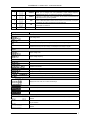
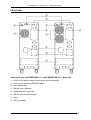
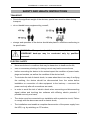
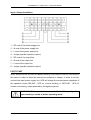
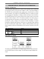
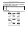
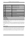
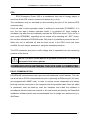
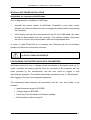
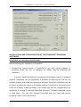
POWERLINE 11 series UPS – Instruction Manual
TABLE OF CONTENTS
TABLE OF CONTENTS........................................................................................................................................ 2
INTRODUCTION .................................................................................................................................................. 3
GENERAL INFORMATION ................................................................................................................................. 3
PURPOSE OF THE POWER SUPPLY............................................................................................................. 3
General features of the battery back-up .................................................................................................................. 3
UPS STRUCTURE ................................................................................................................................................. 4
FRONT PANEL................................................................................................................................................. 4
REAR PANEL ................................................................................................................................................... 6
SAFETY AND HEALTH INSTRUCTIONS ......................................................................................................... 7
TRANSPORT .................................................................................................................................................... 7
ELECTRIC SAFETY......................................................................................................................................... 7
INSTALLATION.................................................................................................................................................... 9
UNPACKING .................................................................................................................................................... 9
INSTALLATION OF THE BATTERY BACK-UP ........................................................................................ 10
CONNECTING THE BATTERY BACK-UP ................................................................................................. 10
Input / Output Installation ..................................................................................................................................... 11
FIRST START ................................................................................................................................................. 11
DESCRIPTION OF THE BACK-UP'S OPERATION ......................................................................................... 12
GENERAL INFORMATION .......................................................................................................................... 12
ZERO MODE (“00” MODE)........................................................................................................................... 12
“BYPASS” MODE (“01” MODE)................................................................................................................... 13
MAINS OPERATION MODE (“02” MODE)................................................................................................. 13
BACK-UP (BATTERY) OPERATION MODE (“03” MODE) ...................................................................... 14
STORAGE CELLS TEST MODE (“04” MODE) ........................................................................................... 14
“SERVICE BYPASS” OPERATION MODE ...................................................................................................... 15
EMERGENCY MODE ......................................................................................................................................... 15
SAFEGUARDS................................................................................................................................................ 16
Against overloads.................................................................................................................................................. 16
Against shorting .................................................................................................................................................... 16
EPO....................................................................................................................................................................... 17
COMMUNICATION BETWEEN THE UPS AND A COMPUTER................................................................... 17
RS232 COMMUNICATION ........................................................................................................................... 17
WinPower SOFTWARE INSTALLATION .................................................................................................... 18
Installation on computers with Windows.............................................................................................................. 18
CONFIGURING THE BATTERY BACK-UP'S PARAMETERS.................................................................. 18
INSTALLATION AND CONFIGURATION OF THE POWERSOFT PERSONAL SOFTWARE .............. 19
Installation on computers with Windows.............................................................................................................. 19
Installation on computers with Linux/Unix .......................................................................................................... 20
Software updates ................................................................................................................................................... 21
ADDITIONAL REMARKS.................................................................................................................................. 22
BATTERY BACK-UP AND POWER GENERATORS ................................................................................. 23
STORAGE, MAINTENANCE ........................................................................................................................ 23
DISPOSAL....................................................................................................................................................... 23
TECHNICAL PARAMETERS............................................................................................................................. 24
INSTALLATION GUIDELINES .................................................................................................................... 24
TECHNICAL DATA ....................................................................................................................................... 25
DIAGNOSTICS OF ERRORS REPORTED BY UPS ......................................................................................... 26
INFORMATION REGARDING REGULATIONS AND WARRANTY ............................................................ 27
DECLARATION OF CONFORMITY ............................................................................................................ 27
WARRANTY................................................................................................................................................... 27
2011/07/22
www.ever.eu
2
POWERLINE 11 series UPS – Instruction Manual
INTRODUCTION
Thank you for purchasing the EVER POWERLINE battery back-up. It belongs to
the latest series of state-of-the-art power supply devices designed to work with
servers, computer networks, as well as data processing systems.
EVER POWERLINE series UPS was designed so as to meet all your expectations
for protection against power loss.
The following manual contains information on operating the device and safety rules.
Familiarising yourself in detail with the manual prior to using the EVER POWERLINE
UPS will help you operate the device correctly.
GENERAL INFORMATION
PURPOSE OF THE POWER SUPPLY
POWERLINE series battery back-ups are ONLINE-class (VFI) devices designed for
work with equipment powered by monophase ~230V mains.
WARNING! POWERLINE battery back-ups were not designed to
work with medical equipment, in particular life and/or health
support devices.
General features of the battery back-up
POWERLINE battery back-ups consist of the following functional units:
•
rectifier unit with PFC (power factor correction),
•
accumulator charger,
•
accumulator unit in a battery module
•
inverter manufactured in high-frequency IGBT technology,
•
automatic bypass system,
•
manual (service) bypass system,
•
microchip control system with measurement units.
The input inverter converts the AC energy into an internal DC bus. The power factor
correction (PFC) system enables a radical reduction of interference transmitted to the
power system. The DC bus is the basic power source for the inverrter creating
a nominal AC true sine wave used to power the receivers. An independent charger is
responsible for charging the accumulator. Its distinctive feature is a very low
2011/07/22
www.ever.eu
3
POWERLINE 11 series UPS – Instruction Manual
alternating
charging
current
component,
which
considerably
prolongs
the
accumulators’ life. Microchip control system (DSP) enables precision and reliability of
the whole power supply system.
The automatic bypass system increases the overall system security.
In the event of a failure of the inverter, the current from the mains will be provided
directly to the load. Thus, the automatic bypass system becomes an additional,
passive safeguard of the load.
Additional function of manual connection of the bypass enables a complete
switch of the load power supply to mains and thus conducting servicing or
maintenance work. Internal electronic circuits (excluding the secured manual bypass
system) can be started by input breaker.
UPS STRUCTURE
FRONT PANEL
2011/07/22
www.ever.eu
4
POWERLINE 11 series UPS – Instruction Manual
No.
Symbol
Name
Description
If the unit is in BYPASS mode or zero mode (STANDBY), pressing this button
allows you to configure the unit’s parameters: output voltage, frequency,
BYBASS mode options. To approve the selection, press ENTER (2)
1
SELECT
2
ENTER
If the unit is in BYPASS mode, parameters set by means of the SELECT key
may be approved by pressing ENTER.
3
OFF
When the power supply is regular, pressing the OFF button causes the unit to
switch to BYPASS mode and turns off the inverter. If the BYPASS mode option
is available, the outlet is powered from the BYPASS line
4
ON
Turns the unit on
Deactivates sound alarms.
LCD
LCD
5
-
Display
Description
Input
Input voltage value
Input voltage frequency
Indicates excessively high input voltage; not displayed if the voltage is regular
Indicates excessively low input voltage; not displayed if the voltage is regular
Output
Output voltage value
Output voltage frequency
Load
Unit load in W or VA
Indicates short-circuit of the unit’s output
Indicates unit overload
Storage cells
Storage cells voltage value
Charge level of storage cells
Indicates overload of the storage cells; the unit will switch to battery mode
Indicates that the storage cells are discharged; the unit will soon switch off
Mode/Error/Warning
Displays the unit’s mode, error codes and warnings
Inverter
Indicates the operational status of the inverter
Bypass
Indicates the operational status of the BYPASS circuits
Output voltage, frequency, BYBASS mode option
If the unit is in STANDBY or BYPASS mode, one of the four output voltage values may be
selected
If the unit is in STANDBY or BYPASS mode, one of the two input voltage frequency values
may be selected
If the unit is in STANDBY or BYPASS mode, one of the two BYPASS mode options may be
selected
2011/07/22
www.ever.eu
5
POWERLINE 11 series UPS – Instruction Manual
REAR PANEL
Rear panel view of POWERLINE 6-11 and POWERLINE 10-11 back-ups
1 – Cover of the power supply and receiver grid connections
2 – Cover of the servicing BYPASS switch
3 – Input safeguard
4 – Parallel port (optional)
5 – Expansion card (optional)
6 – RS232 communications port
7 – Fans
8 – EPO connector
2011/07/22
www.ever.eu
6
POWERLINE 11 series UPS – Instruction Manual
SAFETY AND HEALTH INSTRUCTIONS
TRANSPORT
•
Due to the significant weight of the devices, special care must be taken during
transport;
•
do not handle heavy equipment by yourself;
•
storage and operation of the device should take place in conditions conforming to
its specification.
WARNING!
Transport,
installation
and
maintenance
of
POWERLINE back-ups may be conducted only by qualified
personnel.
ELECTRIC SAFETY
•
Never work alone in conditions that may be hazardous to health and/or life;
•
even a momentary shorting of a strong current may lead to severe burns;
•
before connecting the device to the mains inspect the condition of power leads,
plugs and sockets, as well as the condition of the device itself;
•
To minimise the risk of electric shock, in cases when there is no way of verifying
the earthing, the device should be disconnected from the mains before
installation or connection of other equipment to the back-up – reconnect the
power cord only after all connections are made;
•
in order to avoid the risk of electric shock when connecting and disconnecting
signal cables and touching two surfaces with differing electric potential, if
possible use only one hand;
•
The device must be connected to an installation with a protective circuit; Failure
to comply with the above can result in electric shock;
•
The installation must enable a complete disconnection of the power supply from
the UPS, e.g. by switching an “S” breaker;
2011/07/22
www.ever.eu
7
POWERLINE 11 series UPS – Instruction Manual
•
The device receiving the current must be connected with an appropriate circuit
protection (manual cut-out or circuit breaker);
•
The device is equipped with an earthing cable which siphons the earth leakage
current to the receivers (e.g. computer hardware). This should be taken into
consideration with residual current safeguards;
WARNING! The receiver line of the emergency power supply
should be equipped with a remote emergency power off (EPO),
located near the main power switch and appropriately marked.
WARNING! Users are forbidden to carry out any maintenance
activities, as they may lead to injury or death. Any repairs and
replacement of batteries should be conducted only by a qualified
representative of the technical support.
WARNING! The battery back-up is disconnected from the mains
only when the power cord is removed from its socket.
WARNING! Since the device is equipped with internal power
source (batteries) the output may provide current even though the
device itself is not connected to the mains.
WARNING! POWERLINE battery back-ups were not designed to
work with medical life support devices.
2011/07/22
www.ever.eu
8
POWERLINE 11 series UPS – Instruction Manual
INSTALLATION
WARNING! Before installing the battery back-up you must
obligatorily familiarise yourself with the safety and health
measures provided in the previous chapter.
UNPACKING
Please inspect the battery back-up upon receipt. Although the product is packed very
carefully it could have sustained damage from shock during transport. Should you
find any damages, please inform the carrier or seller immediately.
WARNING! The device is delivered with its accumulator connected.
The battery back-up is packed in a manner enabling safe transport (including by
forklift truck). To unpack the device:
•
carefully cut the protective bands,
•
slide the cardboard cover off,
•
remove the foam safeguards,
•
according to H&S instructions, remove the battery back-up from the wooden
transport pallet (this may require assistance),
•
place the back-up in the installation location using the transport castors,
•
block the castors.
Keep the packaging for future transportation of the device.
Verify the contents of the package, which should include:
•
the battery back-up,
•
1 RS232 communication cable,
•
Instruction manual on CD,
•
warranty card.
2011/07/22
www.ever.eu
9
POWERLINE 11 series UPS – Instruction Manual
INSTALLATION OF THE BATTERY BACK-UP
When choosing the installation spot you must take the device's weight into account.
The back-up should only be used in rooms whose dustiness, temperature and
moisture levels conform with the device's specification. In order to ensure correct
operation of the back-up, appropriate cooling conditions for the device must be
provided. For this reason the ventilation openings on the back-up's case must be
uncovered and the distance between the back-up and other objects should be kept
according to the guidelines (technical parameters table).
WARNING! The device must not be installed close to flammable
materials!
CONNECTING THE BATTERY BACK-UP
The connection should meet the requirements concerning the cable cross-sections
and installed safeguards – cf. technical parameters table.
WARNING! Connecting of the battery back-up to the mains should
be performed only by a qualified and authorised personnel.
WARNING! The battery back-up is disconnected from the mains
only when the power cord is removed from its socket.
It is recommended that the safety circuits of the building function as one of the
protection measures. Their parameters should be adjusted to the type and
dimensions of the load connected to the installation (technical parameters table).
2011/07/22
www.ever.eu
10
POWERLINE 11 series UPS – Instruction Manual
Input / Output Installation
1 – PE cord of the power supply line
2 – N cord of the power supply line
3 – L cord of the power supply line
4 – Jumper (parallel operation option)
5 – PE cord of the output line
6 – N cord of the output line
7 – L cord of the output line
8 – Jumper (parallel operation option)
FIRST START
When started for the first time the battery back-up may require to be left connected to
the mains in order to allow the internal accumulators to charge. In order to do this,
connect the input power supply line. UPS will charge the accumulators regardless of
the operation mode (ONLINE – UPS on, inverter working, or OFFLINE – UPS off,
inverter not working, output powered by the bypass system).
WARNING! Back-up's batteries reach their full capacity after
approximately a month of mains operating mode.
2011/07/22
www.ever.eu
11
POWERLINE 11 series UPS – Instruction Manual
DESCRIPTION OF THE BACK-UP'S OPERATION
GENERAL INFORMATION
The POWERLINE battery back-up is a state-of-the-art electronic device constituting
an autonomous source of true sine wave voltage of ~230V. This device belongs to
the ONLINE-class uninterruptable power supply group, characterized by constant
power processing. This enables the POWERLINE back-up to condition the power
from the supply line. Regardless of volatage variations and input current deviations,
the POWERLINE back-up at all times maintains at the output a clear true sine wave
with the constant voltage of ~230 V. The back-up operates in the mains mode (i.e.
not drawing power from the battery) in the wide range of input voltages ~176÷276 V,
providing the ~230 V voltage to the receivers. Another advantage of constant
processing in ONLINE-class back-ups is that there is no interruption when switching
the load to another power supply (mains – battery). Switching between mains and
battery operation modes are imperceptible for the receivers connected to the UPS
output.
Code
00
01
02
03
04
Operational status
Zero mode (STANDBY)
BYPASS mode
Mains operation mode
Charge level of storage cells at
Battery
0~20%
operation
Charge level of storage cells at
mode
21~100%
Storage cells test mode
Indication
None
A single sound signal every 2 minutes.
None
A single sound signal every 1 second.
A single sound signal every 4 seconds.
None
ZERO MODE (“00” MODE)
The display presents information on the battery charge status and input parameters
(the value and frequency of input voltage). The UPS does not supply voltage to the
output.
2011/07/22
www.ever.eu
12
POWERLINE 11 series UPS – Instruction Manual
“BYPASS” MODE (“01” MODE)
The back-up switches to BYPASS mode in the event of inverter overload, exceeding
the acceptable temperature, damage of the inverter and after turning the device off
with the “0” button on the panel. In the BYPASS mode the voltage is provided to the
output directly from the input line through the mechanical switch (transmitter). If the
UPS switches to BYPASS mode because of overload or exceeding the acceptable
temperature, then it will automatically conduct periodical examinations of the load
and the inverter’s temperature. When the above values return to normal levels, the
inverter is reconnected.
In BYPASS mode, the unit does not provide any protection against voltage decay.
Voltage from the input line is switched to the unit’s output through an internal filter.
MAINS OPERATION MODE (“02” MODE)
Connecting the battery back-up to the mains results in voltage occurring at the
output. The power is then provided to the output by internal BYPASS system. When
the power supply is connected, also the back-up’s batteries are charged.
2011/07/22
www.ever.eu
13
POWERLINE 11 series UPS – Instruction Manual
The back-up is started only after pressing the “ON” button on the front panel for
approx. 1 second. After the completion of diagnostics UPS is ready for operation.
If the mains voltage is irregular (excessively low or high voltage, frequency outside
the operating range), the unit will switch to battery mode. If the voltage is correct,
UPS turns on the inverter and is ready for operation.
In the mains operation mode a voltage of ~230 V is present at the output of the UPS
WARNING! Turning off the back-up with the button on the panel
will not disconnect the voltage from the output. The output voltage
disappears only after disconnecting the input power supply line.
BACK-UP (BATTERY) OPERATION MODE (“03” MODE)
In the back-up operation mode the true sine wave output voltage is generated by the
accumulator until the mains voltage returns, the accumulator is discharged or an
emergency situation takes place
In the event of no mains voltage, the unit is activated in the same way as in mains
operation mode, however the difference is that following the completion of self test
the panel displays the battery mode screen.
STORAGE CELLS TEST MODE (“04” MODE)
When in the storage cells test mode, the LCD panel displays the same information as
in the battery operating mode. This mode has the “04” code. In this mode, the
excessively low or excessively high input voltage indicators are not available.
The storage cells test mode is activate for approx. 10 seconds by pressing the “ON”
button when the UPS is in mains operation mode (“02” MODE).
2011/07/22
www.ever.eu
14
POWERLINE 11 series UPS – Instruction Manual
“SERVICE BYPASS” OPERATION MODE
This operation mode enables the servicing of the UPS without the need to disconnect
power from the receivers plugged into the UPS output.
WARNING! In the service BYPASS operation mode the receivers
powered by UPS output are in no way protected from power loss in
the mains. In this mode the UPS is completely disconnected from
the output.
EMERGENCY MODE
In this mode, the unit sends the appropriate error codes to the LCD panel and emits
sound signals as per the following table.
2011/07/22
www.ever.eu
15
POWERLINE 11 series UPS – Instruction Manual
Code
01
02
03
Unit operational status
Overload in mains mode; the UPS
is in BYPASS mode
Overload in mains mode; the
inverter continues to operate
Overload in battery mode; early
warning
Indication
A double sound signal every 1 second.
A double sound signal every 1 second.
A double sound signal every 1 second.
05
Incorrect DC bus voltage
Continuous sound signal
06
Incorrect inverter operation
Continuous sound signal
07
Overload in battery mode; output
cut-off
Continuous sound signal
08
Maximum temperature exceeded
Continuous sound signal
09
Output short circuit
Continuous sound signal
10
Incorrect communication
Continuous sound signal
12
Damaged inverter relay
Continuous sound signal
14
Damaged battery thyristor
Continuous sound signal
15
Parallel operation errors
Continuous sound signal
22
Incorrect fan operation
A single sound signal every 1 second.
23
Damaged batteries and loader
A single sound signal every 1 second.
SAFEGUARDS
Against overloads
An overload condition is signalled by the relevant code on the LCD panel and
a sound signal (cf. Table 1).
If the overload reaches 105-130% of the maximum load, the UPS will switch into
BYPASS mode after 10 minutes. If the overload exceeds 130%, the UPS will switch
into BYPASS mode after 1 second and disconnect the output power supply after 1
minute.
Against shorting
The unit signals a short circuit by means of the relevant code on the LCD panel and
a sound signal. When shorting occurs, the output power supply will be disconnected.
If during a shorting signalling the UPS is shut down and the shorting is not removed,
the UPS will switch into BYPASS mode, which will trigger the input circuit breakers.
2011/07/22
www.ever.eu
16
POWERLINE 11 series UPS – Instruction Manual
EPO
EPO (Emergency Power Off) is a mechanism that cuts off energy supply to
receivers at the UPS output in extreme situations (e.g. a fire).
The mechanism may be activated by short-circuiting the pins of the external EPO
connector (trip).
If the unit was in mains operation mode, it switches to zero mode (STANDBY). If, in
turn, the unit was in battery operation mode, it is switched off. Input voltage is
reinstated only after the user manually removes the EPO short circuit. If the unit is in
zero mode (STANDBY), signalling can be turned off by pressing the “OFF” button;
the unit then switches to BYPASS mode. Only then is it possible to power on the unit
When the unit is switched off and the short circuit in the EPO circuit has been
rectified, the unit may be powered on using the standard procedure.
The EPO connector pins have a safe voltage that is separated from the remaining
systems of the device.
NOTE! The EPO circuit must be a separate circuit and it is forbidden
to connect it to other systems.
COMMUNICATION BETWEEN THE UPS AND A COMPUTER
RS232 COMMUNICATION
POWERLINE series battery back-ups come with enhanced control features. The user
can work with a RS232 communications port or optionally an Ethernet port (for backups equipped with SNMP card). In order to ensure correct cooperation the battery
back-up must be connected to the computer with the provided cable. After the cable
is connected, start the back-up, start the computer and install the software in
accordance with the instruction manual or the instructions provided by the PowerSoft
installation software (which can be downloaded free of charge from www.ever.eu) or
WinPower.
2011/07/22
www.ever.eu
17
POWERLINE 11 series UPS – Instruction Manual
WinPower SOFTWARE INSTALLATION
Installation on computers with Windows
Prior to beginning the installation of WinPower:
•
Uninstall the current version of WinPower, PowerSoft or any other control
software (in situations where the user is changing the battery back-up protecting
the computer),
•
If the battery back-up will communicate with the PC via a USB cable, this cable
should be disconnected from the computer. The software installer will prompt
the user to connect the communication cable at the appropriate time.
In order to install PowerSoft on a computer with Windows just run the software
installer and follow the instructions onscreen.
WARNING! When the software prompts for a serial number, please
key 511C1-01220-0100-478DF2A.
CONFIGURING THE BATTERY BACK-UP'S PARAMETERS
WinPower allows the user to change certain parameters of the battery back-up. To
make it possible the battery back-up must be connected to the computer with the
cable provided by the manufacturer and the user must be logged in with
Administrator privileges. The default administrator password is set to “Administrator”.
After logging in the user can change the password.
The screenshot below features the parameters that the user can modify in the
software.
•
Input frequency range for BYPASS,
•
Voltage range for BYPASS,
•
Panel keys’ functions and sound alarms settings,
•
Device behavior after turning off.
2011/07/22
www.ever.eu
18
POWERLINE 11 series UPS – Instruction Manual
INSTALLATION AND CONFIGURATION OF THE POWERSOFT PERSONAL
SOFTWARE
Installation on computers with Windows
Before beginning the installation of PowerSoft:
•
Uninstall the current version of PowerSoft or any other control software (in
situations where the user is changing the battery back-up protecting the
computer),
In order to install PowerSoft on a computer with Windows (the list of operating
systems compatible with the application is available at www.ever.eu) just run the
software installer and follow the instructions onscreen. During the installation you will
be asked to select the model of the battery back-up connected to the computer on
which the software is being installed. This setting may also be changed when the
application is running.To uninstall PowerSoft select the "Uninstall PowerSoft" option
in Start Menu. You can also uninstall PowerSoft from the "Add and remove
programs" menu in the control panel.
2011/07/22
www.ever.eu
19
POWERLINE 11 series UPS – Instruction Manual
Installation on computers with Linux/Unix
The binary version of the application for Linux/Unix systems is provided in the
following formats:
CentOS, RedHat, Suse Linux, Fedora Core
For the following systems: CentOS, RedHat, Suse Linux, and Fedora Core the
software is provided in the form of a RPM package. The software can be installed by
using any package manage available for the system installed. If you are using the
command line the software is installed by entering the following command:
rpm –ivh powersoftpersonal-x.x.x.i386.rpm
Users working with the PowerSoft must have root privileges to install the software
and use it. After installation the application may be found in the /usr/local/powersoft
directory.
To uninstall the application enter the following command:
rpm –ev powersoftpersonal-x.x.x
Debian
For the Debian systems the software is provided in the form of a DEB package. The
software is installed via the following command:
dpkg –-install powersoftpersonal-x.x.x.deb
To uninstall the application enter the following command:
dpkg –-remove powersoft
FreeBSD
For FreeBSD systems the software is provided in the form of the default package
format designed for FreeBSD systems. The software is installed via the following
command:
pkg_add powersoftpersonal-x.x.x.tbz
To uninstall the application enter the following command:
pkg_delete powersoft
2011/07/22
www.ever.eu
20
POWERLINE 11 series UPS – Instruction Manual
Starting the software
After installation the system service is started automatically, while the control panel
application can be found at /usr/local/powersoft.
Please note that for the Polish diacritics to be correctly displayed the system locale
should be Polish.
Software updates
Windows systems
The software installer for Windows systems has a built-in automatic updater.
PowerSoft may regularly check for new software versions and notify the user when
updates are available. By default the software check for updates after user log-in.
This setting may be changed in the "Update configuration" item in the system's
programme menu.
Linux/Unix systems
In the case of Linux/Unix systems PowerSoft may be updated by downloading the
new package from www.ever.eu.
In the case of CentOS, RedHat, Suse Linux, and Fedora Core Powersoft may be
updated by entering the following command:
rpm –Uv powersoftlite-x.x.x
In the case of Debian and FreeBSD systems we recommend uninstalling the old
version and then installing the new version of the software. Commands which enable
these operations are described in the instruction manual available at www.ever.eu.
2011/07/22
www.ever.eu
21
POWERLINE 11 series UPS – Instruction Manual
ADDITIONAL REMARKS
WARNING! Product for commercial and industrial applications in
second environment. Applying additional preventive measures or
limiters in the installation may be required in order to prevent the
emission of disturbances.
WARNING! No service elements located inside the battery back-up
are to be modified by the end user.
•
Damaging the warranty seal will void the warranty for the given device.
•
Any repairs should be conducted only by a qualified representative of the
technical support.
•
The battery back-up may not perform as expected if the powered equipment
draws high impulse power. In practice this means that even though mean power
of the protected equipment does not exceed the range of powers accepted by the
battery back-up, the equipment will cause the UPS to shut down. This happens
because the protected equipment temporarily draws power that significantly
exceeds the nominal power of the battery back-up, which causes a detection of
an overload and the resulting shutdown. This situation may take place in the
following cases:
Television sets and monitors (as they are switched on the picture tube is
degaussed which temporarily requires a lot of power),
Laser printers (drum warming cycle),
Other products with similar operating features.
Because of this, if a battery back-up is to be used with equipment other than
computers, its compatibility with equipment used must be verified. In order to do this,
the examined device should be connected to the battery back-up and its operation
should be observed in all modes, i.e. start-up, shutdown, stand-by, etc.
2011/07/22
www.ever.eu
22
POWERLINE 11 series UPS – Instruction Manual
BATTERY BACK-UP AND POWER GENERATORS
The POWERLINE series battery back-ups are ONLINE-class devices. By design, the
battery back-up tolerates mains voltage variations in the range of ~176÷276V, as well
as frequency variations of ±4 Hz with respect to the nominal frequency of 50 Hz.
When working with a power generator, the frequency of the generator’s voltage is
variable and strictly dependent on the load value changes. If the frequency value
exceeds tolerance limits, the back-up will deem it incorrect and switch into battery
operation mode.
STORAGE, MAINTENANCE
The battery back-up should be stored in a cool and dry place, in operating position,
with accumulators completely charged:
•
In temperature between 0°C and +30°C the accumulat or should be charged every
6 months;
•
In temperature between +30°C and +45°C the accumul ator should be charged
every 3 months.
DISPOSAL
Appropriate disposal of used up electric and electronic equipment helps to avoid
consequences resulting from the presence of dangerous materials, as well as
inappropriate storage and processing of such equipment, which may be hazardous to
human life and the environment.
Act dated 29 July 2005 on used up electric and electronic equipment, article 22.1
items 1 and 2.
According to the regulations binding in the European Union, a
crossed rubbish bin symbol means that when a product is no
longer used it should be disposed of at a special waste pickup site.
This concerns the device itself, as well as other accessories
marked with this symbol. Do not dispose of those products
together with unsorted household waste.
Method of safe removal of the batteries from the appliance:
The batteries should be removed from the appliance by an authorised service outlet
or by a duly authorised electrician.
2011/07/22
www.ever.eu
23
POWERLINE 11 series UPS – Instruction Manual
TECHNICAL PARAMETERS
INSTALLATION GUIDELINES
PARAMETER / UPS
Apparent / active power
POWER SUPPLY PARAMETERS
Power supply system layout
Nominal input voltage
Nominal input current
Max. input current
Nominal input frequency
Efficiency
Min. cable cross-section
Line safeguards
OUTPUT PARAMETERS
Output system layout
Nominal output voltage
Nominal output current
Max. output current
Min. cable cross-section
Line safeguards
ENVIRONMENTAL PARAMETERS
Amount of heat radiated in
nominal operating conditions
Operating temperature
Storage temperature
Humidity
Altitude (above sea level)
MECHANICAL PARAMETERS
Dimensions (h x w x d)
Weight
Operating expanse gap
2011/07/22
POWERLINE 6 1/1
6 kVA / 4.2 kW
POWERLINE 10 1/1
10 kVA / 7kW
1P3W
230 V
25 A
45 A
40 A
74 A
50 Hz
> 90 %
10 mm2
2 x 50 A (chk C)
16 mm2
2 x 80 A (chk C)
1P3W
230 V
19 A
45 A
10 mm2
2 x 50 A (chk B)
31 A
74 A
16 mm2
2 x 80 A (chk B)
1500 BTU
2400 BTU
0 – 40 °C
0 – 40 °C
< 95 %
< 1000 m
717 x 260 x 570 mm
90 kg
93 kg
Front: > 200 mm
Sides: > 100 mm
Back: > 300 mm
www.ever.eu
24
POWERLINE 11 series UPS – Instruction Manual
TECHNICAL DATA
PARAMETERS / MODEL
POWERLINE 6-11
POWERLINE 10-11
Output power 1)
6 kVA / 4.2 kW
10 kVA / 7kW
Working environment
Office or industrial rooms with low level of pollution
Operating temperature 2)
0 ÷ +40°C
Storage temperature
0 ÷ +40°C
Relative humidity for operation
< 95 % (without condensation)
Relative humidity for storage
< 95 % (without condensation)
Altitude (above sea level) 3)
Up to 1000 m
Maximum length of outgoing cables
< 10 m
MAINS OPERATION MODE
~176 ÷ 276 V ± 2 %
Input voltage
Frequency of input voltage
46 ÷ 54 Hz ± 1 Hz
Output voltage
~230 V ± 1 %
Switching thresholds: Mains – UPS
~176 V / ~276 V ± 2 %
Shape of output voltage
Sinus
Time to switch to UPS
0
BACK-UP (BATTERY) OPERATION MODE
Output voltage (effective value)
~230 V ± 1 %
Sinus
Shape of output voltage
Switching thresholds: UPS – mains
~180 V / ~260 V ± 2 %
Frequency of output voltage
50Hz ± 1 Hz
Filtering of output voltage
LC
Shorting safeguard
Electronic
Overload protection
Electronic
Time to switch back to mains operation
0 ms
Internal batteries support time
9 / 12 / 28 min
6 / 8 / 20 min
(100 % / 80 % / 50 % Pmax)*
Accumulator
20 x VRLA 12V / 7 Ah
20 x VRLA 12 V / 9 Ah
Maximum charging time of internal batteries
< 5 h**
MECHANICAL PARAMETERS
Dimensions (h x w x d)
717 x 260 x 570 mm
UPS weight
90 kg
93 kg
Battery module weight
N/a
EQUIPMENT
Outlet sockets
Power rack
Signalling
LCD panel, sound signals
2 x 50 A (D) circuit breaker – protection at the mains side
Cut-out
Communication interface
RS232, SNMP/HTTP network control card – optional
Note: The manufacturer reserves the right to change the abovementioned parameters without notice.
* Support times can be extended with battery modules, according to the customer’s needs
** Charging time to 90% battery capacity, following a prior discharge with a load of 80% Pmax
Notes:
1)
For normal operation of the battery back-up the load connected to its output should not exceed 80% of value indicated in the table. Reserve power is essential to
2)
Continued exposure of the battery back-up to the temperature of the surrounding exceeding +25°C will shorten the life of batteries.
3)
If the altitude above sea level increases beyond the provided limit the permitted load power of the batter back-up decreases.
ensure continuous operation of connected devices in case of momentary rushes in load current.
2011/07/22
www.ever.eu
25
POWERLINE 11 series UPS – Instruction Manual
DIAGNOSTICS OF ERRORS REPORTED BY UPS
Possible cause
The unit switched to an
Error code “08”,continuous
error state due to
sound signal
exceeding maximum
permitted temperature
Solution
Make sure that the unit is not overloaded, the fans are not
blocked, and the surrounding temperature is not excessively
high. Wait 10 minutes before powering on the unit in order for to
cool it down. If the problem was not eliminated, contact technical
support.
Disconnect all receivers. Turn off the unit. Make sure that the
Error code “09”,continuous
Short circuit on the
receivers are not damaged and check whether the UPS has no
sound signal
unit’s output
internal errors, and the reconnect the receivers. In the event of a
problem concerning the UPS, contact technical support.
Error code “05” or “09”,
continuous sound signal
The UPS switches on in
battery mode (MODE “03”)
The unit switched to an
error state due to an
Contact technical support
internal error
Input voltage or
frequency exceeds
Check the power source
permitted levels
Check the receivers and disconnect non-critical receivers.
Error code “07”, continuous
Receiver overload or
Recalculate the power load and reduce the number of receivers
sound signal
short circuit.
connected to the unit. Check whether any of the receivers are
damaged.
Warning – code “23”, sound
Damaged storage cells
signal every 1 second
or loader
Error code “11”,continuous
sound signal
The UPS does not operate
although the mains voltage is
correct
Contact technical support
Low charge level of
storage cells or storage
Check the condition of storage cells
cells disconnected
service BYPASS switch
damaged
Contact technical support
The storage cells are
Leave the unit connected to the mains for at minimum 10 hours
not fully charged
in order to fully charge the storage cells.
The battery support time has
Unit overload
Check the receivers and disconnect non-critical receivers.
become shorter
Storage cell capacity
decrease caused by
Replace the storage cells
aging
The “I” has been
pressed for an
insufficient period of
The unit does not switch on
time
after pressing the “ON”
No storage cells are
button
connected to the unit or
the voltage of storage
Press the “ON” button for at least 1 second
Check the connection of storage cells or charge the storage cells
cells is too low
Unit error
2011/07/22
Contact technical support
www.ever.eu
26
POWERLINE 11 series UPS – Instruction Manual
INFORMATION REGARDING REGULATIONS AND
WARRANTY
DECLARATION OF CONFORMITY
The UPS structure conforms with applicable subject norms.
WARRANTY
A separate document attached to the product constitutes the warranty. The
document must meet all formal requirements (e.g. the fields: serial number,
model/type, date of sale, and dealer stamp must be filled out).
The manufacturer made all efforts to ensure that products offered are free of material
and workmanship defects. The company's liability under the warranty is limited to
repairs or replacement of products with such defects. The manufacturer shall make
the decision as to how the defect is removed. The warranty does not cover devices
with mechanical damages that occurred as a result of negligence of incorrect use nor
devices subjected to any modifications made by the user. Apart from the
arrangements included in the warranty card EVER Sp. z o.o. does not grant any
guarantee or warranty, including warranty of merchantability or fitness for particular
purpose.
Apart from the arrangements included in the warranty card EVER Sp. z o.o. shall not
be liable for direct, indirect, specific, incidental or consequential losses incurred in the
course of using the battery back-up, even in cases when the buyer was warned
about such losses being a possibility. The company shall not be liable for any costs,
such as loss of profit or revenue, cost of equipment, costs of equipment use, costs of
software, data, replacement products, claims of third parties or other costs.
2011/07/22
www.ever.eu
27