1
EPTZ 100
Day / Night Speed Dome Camera
INSTALLATION / OPERATION
1 SAFETY WARNINGS
•
Do not place the device near to heaters, furnaces, other heat sources or under direct solar irradiation.
•
Operate the device only in locations providing the tolerable operating temperature range 0°C~40°C.
•
For cleaning, make sure the device is plugged off and only use a damp cloth without acid detergent.
•
Install the device only in dry and dustproof surroundings. Protect the device against any liquid’s penetration.
•
Avoid the penetration of any artefacts, e.g. through ventilation slots.
•
Do not open the device yourself. In case of malfunction, contact your local installer or dealer. Unauthorized opening of the
device will annul the warranty claim!
•
Use the device only for purposes described in this manual.
•
Operate the device only with the power source indicated in this user manual.
ATTENTION! This is a class A product which may cause radio interference in a domestic environment; in this
case, the user may be urged to take adequate measures.
This equipment has been tested and found to comply to part 15 of the FCC Rules. These limits are designed to
provide reasonable protection against harmful
interference in a residential installation. This equipment generates, uses and can radiate radio frequency
energy and, if not installed and used in accordance with the instructions, may cause harmful interference to
radio communications. However, there is no guarantee that interference will not occur in a particular
installation. If this equipment does cause harmful interference to radio or television reception, which can be
determined by turning the equipment off and on, the user is encouraged to try to correct the interference by
one or more of the following measures:
• Reorient or relocate the receiving antenna.
• Increase the separation between the equipment and receiver.
• Connect the equipment into an outlet on a circuit different from that to which the receiver is connected.
• Consult the dealer or an experienced radio/ TV technician for help.
This Product is RoHS compliant.
WEEE
Your EverFocus product is designed and
manufactured with high quality materials and
components which can be recycled and reused.
This symbol means that electrical and electronic
equipment, at their end-of-life, should be
disposed of separately from your household
waste.
Please, dispose of this equipment at your local
community waste collection/recycling centre.
In the European Union there are separate
collection systems for used electrical and
electronic product.
Please, help us to conserve the environment we
live in!
Ihr EverFocus Produkt wurde entwickelt und
hergestellt mit qualitativ hochwertigen Materialien
und Komponenten, die recycelt und wieder
verwendet werden können.
Dieses Symbol bedeutet, dass elektrische und
elektronische Geräte am Ende ihrer
Nutzungsdauer vom Hausmüll getrennt entsorgt
werden sollen.
Bitte entsorgen Sie dieses Gerät bei Ihrer örtlichen
kommunalen Sammelstelle oder im Recycling
Centre.
Helfen Sie uns bitte, die Umwelt zu erhalten, in
der wir leben!
The information in this manual was current upon publication. The manufacturer reserves the right to revise and improve his products.
Therefore, all specifications are subject to change without prior notice. Misprints reserved.
Please read this manual carefully before installing and using this unit. Be sure to keep it handy for later reference.
2
EPTZ100_ma_en_rev03.doc
TABLE OF CONTENTS
SAFETY WARNINGS................................................................................................................ 2
INTRODUCTION ...................................................................................................................... 5
2.1 Features ............................................................................................................................. 5
2.2 Delivery scope..................................................................................................................... 5
2.3 Optional accessories ............................................................................................................ 5
2.4 Specifications ...................................................................................................................... 6
2.5 Dimensions ......................................................................................................................... 8
2.5.1
Dimensions with ceiling mount adapter .......................................................................... 8
2.5.2
Dimensions with recessed ceiling mount adapter ............................................................ 8
2.5.3
Dimension EPTZ 100 with wall mount bracket EPTZ 100 WLM ........................................ 9
2.5.4
Dimensions wall bracket EPTZ 100 WLM ....................................................................... 9
2.5.5
Dimension EPTZ 100 with ceiling pendant bracket EPTZ 100 CPM ................................ 10
2.5.6
Dimension ceiling pendant bracket EPTZ 100 CPM....................................................... 10
3 INSTALLATION ...................................................................................................................... 11
3.1 Mechanical........................................................................................................................ 11
3.1.1
Ceiling mount ............................................................................................................ 11
3.1.2
Recessed ceiling mount.............................................................................................. 12
3.1.3
Wall mount ................................................................................................................ 13
3.1.4
Ceiling pendant mount................................................................................................ 14
3.2 Electrical ........................................................................................................................... 15
3.2.1
Video ........................................................................................................................ 15
3.2.2
Power ....................................................................................................................... 15
3.2.3
RS-485 ..................................................................................................................... 16
3.2.4
Alarm........................................................................................................................ 19
3.3 Communication settings ..................................................................................................... 20
3.3.1
Baud rate and Protocol ............................................................................................... 20
3.3.2
RS-485 ID (address) .................................................................................................. 21
3.3.3
RS-485 bus termination .............................................................................................. 23
3.4 Initial Start......................................................................................................................... 23
4 OSD menu setup .................................................................................................................... 23
4.1.1
Operation in Setup Menu ............................................................................................ 23
4.1.2
Menu Structure .......................................................................................................... 24
4.1.3
Main menu ................................................................................................................ 26
4.1.4
System info ............................................................................................................... 26
4.1.5
Display...................................................................................................................... 26
4.1.6
Camera..................................................................................................................... 27
4.1.7
Scan ......................................................................................................................... 31
4.1.8
Control...................................................................................................................... 35
4.1.9
Privacy Mask ............................................................................................................. 36
4.1.10 Alarm........................................................................................................................ 37
4.1.11 Initialize..................................................................................................................... 37
5 OPERATION WITH EKB 500 KEYBOARD ................................................................................ 38
5.1 EKB 500 operation with EverFocus protocol (EVF-2) ........................................................... 39
5.1.1
EPTZ 100 setup menu................................................................................................ 40
5.1.2
Preset positions ......................................................................................................... 40
5.1.3
Autopan .................................................................................................................... 40
5.1.4
Preset tours............................................................................................................... 41
5.1.5
Pattern tours.............................................................................................................. 41
5.1.6
Remote switching of EPTZ 100 output relay ................................................................. 41
5.2 EKB 500 Operation with Pelco-D/P Protocol ........................................................................ 42
5.2.1
EPTZ 100 setup menu................................................................................................ 42
5.2.2
Preset positions ......................................................................................................... 42
5.2.3
Autopan .................................................................................................................... 43
5.2.4
Preset tours............................................................................................................... 43
5.2.5
Pattern tours.............................................................................................................. 43
1
2
3
EPTZ100_ma_en_rev03.doc
Remote switching of EPTZ 100 output relay ................................................................. 44
5.2.6
APPENDIX A: Basic Settings at EKB 500 keyboard.................................................................... 45
6.1 COM PORT SETTING - RS-485 interface setting.................................................................. 45
6.2 DEVICE SETTING > CAMERA ........................................................................................... 45
7 APPENDIX B: Basic Settings at EverFocus DVR ....................................................................... 46
7.1 EDR / EDVR / EDSR series (except EDSR100, EDSR100H) ................................................. 46
7.2 ECOR / PARAGON series .................................................................................................. 46
8 Appendix C: Troubleshooting.................................................................................................... 47
8.1 General malfunction ........................................................................................................... 47
8.2 Recovering Communication Settings of Camera Module........................................................ 47
6
4
EPTZ100_ma_en_rev03.doc
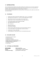
2 INTRODUCTION
The mini PTZ speed dome EPTZ 100 provides ideal discreet surveillance for CCTV indoor applications.
Engineered with the latest Digital Slow Shutter (DSS) x128 technology, EPTZ 100 can improve CCD
sensitivity, producing quality images also under low light conditions.
EPTZ 100 offers enhanced features such as privacy zones, noise reduction and 4 pattern tours with total
40 minutes duration.
2.1
2.2
FEATURES
•
Compact size design for discreet surveillance (only 114 mm / 4.5" diameter)
•
100x total zoom (10x optical: 3.8 ~ 38 mm and 10x digital autofocus zoom)
•
High resolution 520 TVL (colour mode), 570 TVL (b/w mode)
•
Image capture in almost complete darkness with DSS 128x max.
•
True day/night operation with automatic IR cut filter
•
High speed pan/tilt (up to 240° /sec.)
•
360° endless pan
•
Digital Noise Reduction
•
4-zone privacy masking
•
RS-485 communication with EverFocus, Pelco-D and Pelco-P protocol
•
4x 10 minutes pattern tour (programmable camera movement)
•
3 alarm inputs, 1 alarm output relay
•
Includes adapter for ceiling surface mount and recessed ceiling mount.
DELIVERY SCOPE
1 x Speed dome camera module
1 x Connector board
1 x Ceiling mount adapter
1 x Metal ring for recessed ceiling mount
1 x Plastic cover ring for recessed ceiling mount
1 x Drilling template for ceiling mount
1 x Accessory / screw set
1 x User manual
2.3
OPTIONAL ACCESSORIES
EPTZ 100 WLM
EPTZ 100 CLM
EKB 500
24 VAC power supply
Wall mount bracket
Ceiling pendant mount adapter
Universal RS-485 controller keyboard
(type depends on sales region)
5
EPTZ100_ma_en_rev03.doc
2.4
SPECIFICATIONS
Camera
Sensor:
Effective pixels:
Horizontal resolution:
Sensitivity:
Video output:
S/N ratio:
Sync. system:
Electronic shutter:
Digital Slow Shutter (DSS)
White balance:
Back light compensation:
Gain:
Flicker cancel:
DNR Dynamic Noise Reduction:
Day/night switching:
Lens
Zoom ratio:
Focus length:
Aperture:
Viewing angle:
Minimum object distance:
Focusing method:
1/4” CCD SONY Super HAD
380.000 (NTSC), 440.000 (PAL)
520 TV lines (colour mode)
570 TV lines (b/w mode)
0,7 lux (F 1.8, 50 IRE – colour mode)
0,02 lux (F 1.8, 50 IRE – b/w mode)
0.005 lux ( DSS x 128)
Composite 1 Vp-p (sync. negative)
over 50 dB
internal
1/60 ~ 1/120.000 NTSC, 1/50~ 1/120.000 PAL,
automatic (ESC) or manual
up to 128 x
auto AWC / ATW mode, manual
adjustable 3 steps / OFF
adjustable 3 steps / OFF
ON / OFF
adjustable 3 steps / OFF
IRC + b/w switching manual / automatic
10x optical autofocus zoom
(+10x digital zoom, max. 100x)
f 3,8 (wide) ~ 38 (tele) mm
F 1.6 (wide) ~ F 2.8 (tele)
51.2° (wide end) to 5.58° (tele end)
1,5 m
auto, one-push AF, manual
Communication
Communication:
Built-in protocols:
Baud rate:
Speed dome address range:
RS-485 simplex 2 wire
EverFocus / Pelco-P / Pelco-D , setup by DIP switch
2400 / 4800 / 9600 bps, setup by DIP switch
1 ~ 255, setup by DIP switch
Alarm
Alarm:
3 inputs, 1 output, with tour / position auto triggering
PTZ / functionality
Horizontal rotation range:
Tilt rotation range:
Auto pan, 2 points scanning:
Auto pan speed:
Auto pan dwell time (A-B points):
Preset positions:
Preset tours:
Dwell time at preset position:
Pattern:
Running to position speed:
Manual pan / tilt speed:
Position accuracy:
360° unlimited rotation
90° with auto flip function
adjustable speeds, adjustable end stops
2, 6, 12, 30, 60, 120o / second
1,3,5,10,30,45 s
64
1 tour with first 16 positions, 4 group tours with 4 positions each,
1 tour with individual setup up to 32 positions
1 ~ 255 s
4 x pattern with up to 800 movements / 600 s PTZ recording each
up to 240° / sec.
0,5° ~ 240° / sec.
0.225°
6
EPTZ100_ma_en_rev03.doc
Alarm:
Proportional pan speed:
Privacy zones:
Setup:
Auto resume:
Video output:
Power
Power source:
Power consumption:
Physical / environment
Connectors:
Ambient temperature:
Humidity:
Protection rating:
Dimensions:
Weight:
Delivery scope:
3 inputs, 1 output, with tour / position auto triggering
yes
4 zones, free adjustable
multiline OSD setup menu
after 1, 2, 3, 4, 5 or 10 min. no activity: go to
BNC cable socket
24 V AC +/- 10%
19 W max. (with PTZ motors)
12 W max. (without PTZ motors)
Video output: BNC cable socket
Power/RS485/Alarm: connector cable, open cable end
cable length: 90 cm
0°C ~ +40°C
85% max
IP20, for indoor applications only
200 (height with ceiling mount adapter) x
114 (diameter camera module) mm
Details in dimension drawing
1.5 kg (camera module incl. adapter board)
speed dome camera, connector board ceiling mount adapter, inceiling mount adapter, user manual, mounting accessories
7
EPTZ100_ma_en_rev03.doc
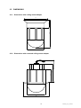
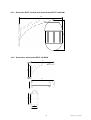
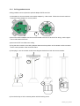
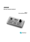
2.5
DIMENSIONS
2.5.1 Dimensions with ceiling mount adapter
202
54
170
114
80
115
~150
2.5.2 Dimensions with recessed ceiling mount adapter
114
166
8
EPTZ100_ma_en_rev03.doc
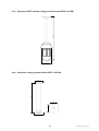
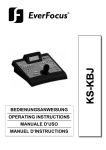
2.5.3 Dimension EPTZ 100 with wall mount bracket EPTZ 100 WLM
225
270
2.5.4 Dimensions wall bracket EPTZ 100 WLM
169,5
140
240
120
140
80
240
60
80
9
EPTZ100_ma_en_rev03.doc
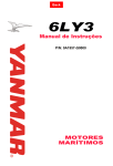
500
2.5.5 Dimension EPTZ 100 with ceiling pendant bracket EPTZ 100 CPM
120
2.5.6 Dimension ceiling pendant bracket EPTZ 100 CPM
300
72
80
80
100
10
EPTZ100_ma_en_rev03.doc
3 INSTALLATION
3.1
MECHANICAL
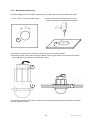
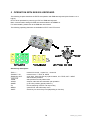
3.1.1 Ceiling mount
The ceiling mount accessories are included in the EPTZ 100 package.
1. Use the drilling template to mark the drilling holes.
1
2) Click the connector board into the ceiling adapter. Follow the red arrow marks at board and ceiling
adapter for correct position.
3
2
Connector
board
C ili
d t
3) Mount the ceiling adapter and connector board to the ceiling. For the cables, use either the side outlet
or a hole in the ceiling.
4) Plug the dome module in the ceiling adapter. Make sure that the position of the camera module
connector fits the connector position of the connector board.
5) After plug-in, turn the camera module some degrees clockwise to latch the camera module.
6
4
5
6) Use the hex key to fix the camera position with the locking screw.
11
EPTZ100_ma_en_rev03.doc
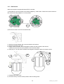
3.1.2 Recessed ceiling mount
Recessed ceiling mount is possible at open ceilings. A metal ring has to be mounted at ceiling side.
1) Cut a 115mm / 4.6" hole into the ceiling.
2) Drill 3 screw holes for mounting in the ceiling
Use the metal ring as template for drilling holes.
1
2
3) Plug the connector board to the dome module and latch it by turning clockwise.
4) Remove the clear dome cover and click the plastic cover ring at the dome cover with some pressure.
Mount the dome cover with ring to the camera module.
3
4
5
5) Position the metal ring at top side of ceiling and mount the prepared speed dome module to the metal
ring with 3 tapping screws.
12
EPTZ100_ma_en_rev03.doc
3.1.3 Wall mount
Wall mount requires the optional bracket EPTZ 100 WLM.
1) Assemble the connector board to the bracket adapter by 3 M4 screws. Follow the red arrow marks at
both board and ceiling adapter for correct position.
1
2) Remove the cable cover from the wall bracket.
2
3) Mount the bracket adapter with connector board to the bracket.
4) Mount the bracket to the wall.
5) Plug the dome module in the ceiling adapter. Make sure that position of the camera
module connector fits the correct position of the connector board.
6) After plug-in, turn the camera module some degrees clockwise to latch the camera module.
3
8
4
6
7
5
7) Assemble the cable cover.
8) Use the hex key to fix the camera position with the locking screw.
13
EPTZ100_ma_en_rev03.doc
3.1.4 Ceiling pendant mount
Ceiling pendant mount requires the optional adaptor EPTZ 100 CLM.
1) Assemble the connector board to the bracket adapter by 3 M4 screws. Follow the red arrow marks at
board and ceiling adapter for correct position.
1
2) Mount the bracket adapter with the connector board to the EPTZ 100 CLM. For wiring, use the upper
hole or side outlet of the tube.
3) Mount the EPTZ 100 CLM to the ceiling.
4) Plug the dome module in the ceiling adapter. Make sure that position of the camera module connector
fits the correct position of the connector board.
5) After plug-in, turn the camera module some degrees clockwise to latch the camera module.
3
2
6
4
5
6) Use the hex key to fix the camera position with the locking screw.
14
EPTZ100_ma_en_rev03.doc
3.2
ELECTRICAL
3.2.1 Video
EPTZ 100 provides a composite 1 Vp-p video output PAL/NTSC (video system depending on ordered
version) with a BNC cable socket.
Cameras and video displaying or processing equipment (DVRs, switchers etc.) require cabling with 75
Ohm video cable, e.g. RG-59, RG-12, and suitable BNC plugs.
Due to inappropriate absorbability, 50 Ohm coax cable (e.g. RG58), antenna cable and further types of
coax cable are not suitable.
Make sure that the video input of the connected video device is terminated with 75 Ohm.
When interconnecting transmission lines (twisted pair, fibre optics, radio) to the speed dome, ensure the
accurate receiver calibration.
3.2.2 Power
EPTZ 100 is powered by 24 VAC voltage. Connector is a 5.5 mm power cable socket.
Make sure that the used power supply complies with the power requirements of the speed dome (19 W
max.). 24 VAC / 1 A power source (or higher current) is recommended.
NOTE: If the power supply is not located near the dome camera, make sure that the installation cables
have sufficient diameter, otherwise the voltage drop over the power line will cause malfunction of
the speed dome (min. 21.4 VAC at speed dome power input with active PTZ motors is required).
NOTE: Do not connect the power until all installation steps are done!
15
EPTZ100_ma_en_rev03.doc
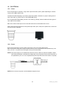
3.2.3 RS-485
EPTZ 100 uses RS-485 simplex wiring; the signal is transferred via a single twisted pair line. CAT5
network cable is recommended, UTP version (unshielded) is sufficient for normal application. A shielded
cable should be used if the installed cables are expected to be highly susceptible to interferences.
Basically, the bus should be created by serial wiring, star wiring is only permitted using signal distributors.
Maximum RS-485 bus cable length is 1200 m. Both the first and the last device are normally 120 Ohm
terminated in order to minimize line reflexions.
DS3 Termination switch ON
Serial RS485 installation
DS3 Termination switch ON
Serial RS485 installation with connector boxes and stubs
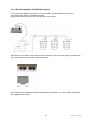
DS3 Termination
DS3 Termination
switch ON
switch ON
DS3 Termination
switch ON
Correct RS-485 star wiring with RS-485 distributor
Incorrect RS-485 star wiring !
16
EPTZ100_ma_en_rev03.doc
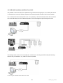
3.2.3.1 RS-485 installation with EKB 500 keyboard
For connection to EKB 500 via RS-485, it is recommended to use the EKB 500 connector box.
The drawing below shows an installation example.
Please make sure that the wires are connected with correct polarity.
Alternatively, it is possible to connect the RS-485 wire directly to the keyboard by using a standard RJ45
plug. The pin assignment is shown in the drawing below.
Basic communication settings for EKB 500 are explained in Appendix A. For further details, please refer
to the EKB 500 user manual.
17
EPTZ100_ma_en_rev03.doc
3.2.3.2 RS-485 installation with EverFocus DVR
It is possible to control the EPTZ 100 speed dome by EverFocus DVR (except 1 Ch. models) via network.
A combined local control by EKB 500 keyboard and remote (network) control by DVR is also possible.
For a combined local and remote PTZ control, it is mandatory that DVR and speed dome are connected
to the same RS-485 port of the EKB 500 keyboard. The RS-485 signal is looped through the DVR.
Combined local and remote PTZ control
Combined local and remote PTZ control with star wring to dome and RS-485 distributor
The drawing below shows an incorrect RS-485 connection for controlling the DVR locally and remotely.
With this way of installation, only local PTZ control is possible.
Incorrect wring for combined local and remote PTZ control
18
EPTZ100_ma_en_rev03.doc
3.2.4 Alarm
EPTZ 100 provides 3 alarm input contacts and 1alarm output relay. It is also possible to trigger the alarm
output relay by EKB 500 keyboard command.
For input contacts, use dry Normal Open (N.O.) contacts only.
The maximum load of output relay contacts is 30 V AC/DC 0.5 A max.
19
EPTZ100_ma_en_rev03.doc
3.3
COMMUNICATION SETTINGS
The setup for general RS-485 parameters - protocol type, RS-485 address and baud rate - is done by DIP
switches, located at the top of the camera module.
Correct settings are essential for communication with the dome controller.
For correct communication, all 3 parameters - protocol, baud rate and RS-485 ID- have to comply with the
PTZ controller settings.
The 120 Ohm termination (DS3) is used at the last dome in the RS-485 bus for avoiding reflections in the
RS-485 bus.
Location of DIP switches:
DS3
DS1
DS2
DS1: Protocol and baud rate
DS2: RS-485 ID (address)
DS3: 120 Ohm termination of RS-485 bus
3.3.1 Baud rate and Protocol
The baud rate setting is done by switch 1 and 2 of DS1:
The telemetry protocol setting is done by switch 3, 4 and 5 of DS1:
20
EPTZ100_ma_en_rev03.doc
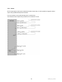
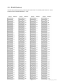
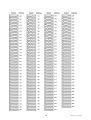
3.3.2 RS-485 ID (address)
The RS-485 ID (address) setting is done by DIP switch DS2. The following table shows the switch
positions for the possible addresses 1 ~ 255:
21
EPTZ100_ma_en_rev03.doc
22
EPTZ100_ma_en_rev03.doc
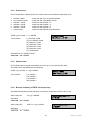
3.3.3 RS-485 bus termination
The last device in an RS-485 bus should be terminated by 120Ohm resistor to avoid reflections on the
bus (for details, please refer to chapter 3.2.3).
The termination is done by DIP switch DS3.
Termination ON
3.4
Termination OFF
INITIAL START
After finishing all installation steps, power on the EPTZ 100.
At power-up, EPTZ 100 will perform an initialization. The communication settings will briefly appear on the
screen. Please check these information to ensure the correct DIP switch settings.
Example:
TYPE: EPTZ100
Firmware: 709M/809Q
BAUDRATE:9600
RS-485 ID: 1
PROTOCOL: EVERFOCUS
4 OSD MENU SETUP
4.1.1 Operation in Setup Menu
Start EPTZ menu:
If DVR Main monitor is selected ("DVR" in LCD display):
C
C
A
M
M
E
N
U
CA
AM
M (hold) + M
ME
EN
NU
U
If no DVR main monitor is selected:
M
M
E
N
U
C
A
M
M
E
N
U
ME
EN
NU
U or C
CA
AM
M (hold) + M
ME
EN
NU
U
or alternatively in both modes:
S
S
H
F
T
P
R
E
S
E
T
E
N
T
E
R
SH
HIIIF
FT
T (hold) + P
PR
RE
ES
SE
ET
T > 999 555 > E
EN
NT
TE
ER
R
Switch between the settings:
JJJO
O
Y
S
T
C
K
OY
YS
ST
TIIIC
CK
K
Enter submenus:
JJJO
O
Y
S
T
C
K
OY
YS
ST
TIIIC
CK
K
in CAMERA > ADVANCED SETUP: IIIR
R
S
RIIIS
S +++
Change the settings:
JJJO
O
Y
S
T
C
K
OY
YS
ST
TIIIC
CK
K
EXIT OSD menu / submenus:
Menu item EXIT/RETURN > JJJO
O
Y
S
T
C
K
OY
YS
ST
TIIIC
CK
K
in CAMERA > ADVANCED SETUP: IIIR
R
S
RIIIS
S ---
Note: Exceptional commands are described in the OSD.
23
EPTZ100_ma_en_rev03.doc
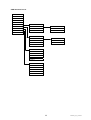
4.1.2 Menu Structure
OSD Structure Part 1:
MAIN MENU
SYSTEM INFO
MAIN SETUP
SYSTEM INFO
TYPE
CAM TITLE
DISPLAY
FIRMWARE
WHITE BAL
CAMERA
BAUDRATE
BACKLIGHT
SCAN
RS-485 ID
MOTION DET
CONTROL
PROTOCOL
FOCUS
FOCUS SETUP
EXPOSURE
MODE
PRIVACY MASK
ALARM
DISPLAY
SPECIAL
ZOOM TRK
INITIALIZE
CAMERA ID
RESET
ZOOM SPEED
EXIT
CAMERA NAME
D-ZOOM
PRESET NUMBER
DISP ZOOM MAG
PRESET NAME
ZOOM POS INIT
PTZ POSITION
LENS INIT
CAMERA
EXPOSURE SETUP
ZOOM SPEED
ADVANCED SETUP
RESCUE MODE
BAUDRATE
PARITY
AUTO PAN
PAN/TILT
PAN ONLY
CIRCLE
BRIGHTNESS
IRIS
SHUTTER
AGC
SSNR
SCAN
ALL PRESET
AUTO PAN
SPEED
ALL PRESET
DWELL
SPECIAL SETUP
GROUP SCAN
RUN
USER PRESET
GROUP SCAN
PRIVACY
GROUP1
DAY/NIGHT
GROUP2
SYNC
GROUP3
COMM ADJ
GROUP4
IMAGE ADJ
TOUR SCAN
PATROL
PATTERN
SENS-UP
TOUR SCAN
GROUP1
IMAGE SETUP
GROUP2
FREEZE
GROUP3
H-REV
GROUP4
V-REV
SPEED
SHARPNESS
DWELL
COLOUR GAIN
RUN
PATROL
PRESET
SPEED
DWELL
RUN
PATTERN 1
RECORD
PREVIEW
RUN
DELETE
24
EPTZ100_ma_en_rev03.doc
OSD Structure Part 2:
MAIN MENU
SYSTEM INFO
DISPLAY
CAMERA
SCAN
CONTROL
CONTROL
PRIVACY MASK
AUTO RESUME
AUTO RESUME
ALARM
POWER ON RESUME
MODE
INITIALIZE
IMAGE FLIP
TIME
EXIT
PRIVACY MASK
MASK 1
MASK 1
MASK 2
POSITION
MASK 3
ENABLE
MASK 4
ALARM
RELAY
INPUT 1
INPUT 2
INPUT 3
OUTPUT
INITIALIZE
POWER ON RESET
CAMERA DEFAULT
FACTORY DEFAULT
LENS REFRESH
CAMERA REFRESH
25
EPTZ100_ma_en_rev03.doc
4.1.3 Main menu
After opening OSD setup the MAIN menu is shown at the screen:
MAIN MENU
SYSTEM INFO
DISPLAY
CAMERA
SCAN
CONTROL
PRIVACY MASK
ALARM
INITIALIZE
EXIT
Select a menu item with UP/DOWN, RIGHT will open submenu.
NOTE: The OSD menu has a timeout function. After 2 minutes with no activity, the OSD menu will close
automatically.
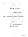
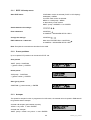
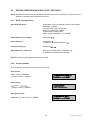
4.1.4 System info
This menu shows the camera type, firmware version and communication settings.
There are no editable items in this menu.
SYSTEM INFO
TYPE
FIRMWARE
BAUD RATE
RS-485 ID
PROTOCOL
EPTZ100
709M809Q
9600
1
EVERFOCUS
4.1.5 Display
The settings in this menu define the overlay displays of the camera.
CAMERA ID
Shows the RS-485 ID on the screen:
ON: display of RS-485 ID
OFF: no display of RS-485 ID
CAMERA NAME
With setting ON, a camera title with up to 16 characters can be entered.
ON: display of camera title (with option for edit)
OFF: no title display
PRESET NUMBER
ON: display number of active preset
OFF: no preset number display
PRESET NAME
ON: display of a freely editable title (up to 16 characters) of the preset
(available for presets 1 ~ 32)
OFF: no display of preset name
PTZ POSITION
ON: show coordinates for pan and tilt in degrees and zoom ratio
OFF: no PTZ position display
RETURN
Returns to main menu
26
EPTZ100_ma_en_rev03.doc
4.1.6
Camera
This menu provides the camera video settings.
CAMERA
ZOOM SPEED
Zoom speed setup in 8 possible levels:
Level 1: slowest to Level 8: fastest
ADVANCED SETTING
Opens submenu for camera features (following chapter)
RESCUE MODE
Mode for recovering serial communication between speed dome and camera
module. This mode is not needed for normal setup. Keep setting OFF.
For details consult APPENDIX C: Troubleshooting
BAUD RATE
Baudrate display for RESCUE MODE. This parameter is not needed for normal
setup.
For details consult APPENDIX C: Troubleshooting
PARITY
Display of parity setting for RESCUE MODE. This parameter is not needed for
normal setup.
For details consult APPENDIX C: Troubleshooting
RETURN
Returns to main menu
4.1.6.1 Advanced setting (camera setup)
NOTE: This menu and its submenus require an operation different from the other EPTZ 100 OSD menus:
Switch between the settings:
Switch to submenu / enter:
Leave the menu:
JJJO
O
Y
S
T
C
K
OY
YS
ST
TIIIC
CK
K
IIIR
I
S
+
R
I
S
+
RIS +
Menu item "EXIT", confirm with IIIR
R
S
RIIIS
S +++
MAIN SETUP
CAM TITLE
Alternative camera title display option. Please leave this setting OFF and use
"CAMERA NAME" in DISPLAY menu for editing / displaying camera title
WHITE BAL
White Balance mode:
ATW
Auto-tracking white balance. ATW continuously checks the whole image,
weights all colours in the picture and updates the white level and colour
temperature which is suitable for constantly changing scene.
2 options are available for ATW indoor and outdoor. Indoor mode tends
to be more blue and outdoor mode adds more red to the whole image.
AWC
Auto white balance. Camera will make colour calibration of the picture
for once and keep the colour temperature until the next command is
given. To refresh the colour, a manual trigger needs to be done to the
AWC when shown on the display.
Manual Manual adjustment of colour preference. With manual setting, the colour
temperature can be fixed which can be suitable for indoor and static
environment.
If the lighting is Tungsten or similar (more natural), try to either add
27
EPTZ100_ma_en_rev03.doc
some blue or reduce some red; if lighting is fluorescent or within white
spectrum, try to either add some red or reduce some blue.
Default values are 30 (for RED) and 40 (for BLUE); it is recommended
not to set the values too far away from these two default values.
BACKLIGHT
Back light compensation improves the image quality in scenes with extreme light behind the
object which usually washes out the image considerably. Back light function is used to
reduce, if necessary, both exposure time and video gain to avoid over-exposure.
Use the back light compensation for sceneries with back light only; under normal light
conditions, the BLC may impair the image quality.
OFF
BLC not active
LOW; MIDDLE; HIGH Levels of BLC gain. Set the level as low as possible to avoid
overmodulation.
MOTION DET
EPTZ 100 does not support this feature. Please leave the setting on OFF.
FOCUS
Submenu for setup of focus modes and features:
ONE_PUSH The one-push function focuses the lens after each pan / tilt / zoom
operation and turns autofocus off after focusing.
This mode is recommended for most applications.
AUTO
The AUTO mode enforces the lens to automatically adjust its
focusing when either the object moves or the scene has changed.
NOTE: The autofocus function requires adequate illumination of the
scenery. Especially in low lux environment, it is recommended to use
the "One Push" autofocus mode, not the "AUTO" mode.
MANUAL
Manual mode to finetune and obtain the optimum focusing.
In certain conditions, such as weak contrast, dark sceneries etc., the
autofocus function of the camera may not get the best focus position.
In such case, the focus can be adjusted manually.
ZOOM TRK Zoom tracking - with setting ON, the lens tries to keep focus also
during zoom in / zoom out operation.
Dependencies zoom modes:
Focus
One-Push
Mode
AUTO
Manual
ZOOM-TRK
ZOOM-TRK
ZOOM-TRK
Action
ON
off
ON
n/a
Change in scene
no action
no action focusing
focusing
no action
Zooming
focusing
focusing focusing
focusing
focusing
off
at stop
off
at stop
Pan/Tilt
focusing at focusing focusing
focusing
no action
& tilting
Go to Preset
stop
at stop
focusing at focusing focusing
focusing
no action
stop
at stop
ZOOM SPEED
Zoom speed setting: FAST or SLOW
D-ZOOM
Value for maximum digital zoom ratio LIMIT x2 ~ x10
DISP ZOOM MAG
ON: Overlay display of zoom position on the screen
28
EPTZ100_ma_en_rev03.doc
EXPOSURE
ZOOM POS INIT
Defines a zoom position after powering up the camera,
range is x1 ~ x10
LENS INIT
Reset of the autofocus lens in case of malfunction
END
Return to CAMERA ADVANCED SETTING page
BRIGHTNESS
Image brightness setting, range 1~100
IRIS
Mode of the lens iris:
AUTO:
automatic iris mode
MANUAL:
manual iris operation
SHUTTER
Electronic exposure control
ESC:
Electronic auto shutter, the shutter speed is
automatically adapted to light conditions
NOTE: This mode item is only available for setup
if IRIS mode is set to "MANUAL"
MANUAL: Manual setup of shutter speed
A.FLK: Flickerless mode. Useful in sceneries with light
sources powered with a frequency different
from the camera
AGC
Automatic Gain Control, gains video signal under low light
conditions.
HIGH: AGC ON, high gain
NORMAL: AGC ON, normal gain
OFF: AGC off (SSNR and SENS-UP are not available in
this mode)
SSNR
Signal noise reduction. This feature improves the signalnoise ratio under low-light conditions.
OFF: no noise reduction
LOW, MID, HIGH: level of noise reduction
NOTE: this feature requires setting AGC: NORMAL or
HIGH
SENS-UP
The SENS-UP function increases the light sensitivity by
interpolation of several images.
AUTO: SENS-UP function active. Enter the submenu to
enter the number of maximum interpolated
pictures (2 ~ 128)
NOTE: Please consider that a higher value
creates brighter pictures, but due to the
longer calculation time moving objects
may appear distorted in the picture.
(effect similar to longer exposure time at
photo cameras)
OFF: no SENS-UP function
NOTE: this feature requires setting AGC: NORMAL or
HIGH
END
Return to CAMERA ADVANCED SETTING page
29
EPTZ100_ma_en_rev03.doc
SPECIAL
Submenu for advanced camera functions:
USER PRESET
Not supported by EPTZ 100
PRIVACY
Keep OFF setting, privacy mask setup is done in the
PRIVACY MASK menu, available in the main menu
DAY/NIGHT
Modes of the day/night switching:
B/W : black/white (night) mode, IR cut filter switched off
COLOUR: colour (day) mode, IR cut filter switched on
AUTO1: day/night switching with short delay time
AUTO2: day/night switching with longer delay time
SYNC:
Synchronization mode, fixed at INTERNAL mode
COMM ADJ
Communication settings for camera interface
ATTENTION:
Do not change any value in this submenu!
Keep default settings:
CAM ID
DISP CAM ID
BAUD RATE
UART MODE
RET PKT
0
OFF
38400
8-N-1
ENABLE
If these settings are changed for whatever reason, the
communication between dome electronics and camera
menu will be broken. In this case consult APPENDIX C
for recovering camera module communication settings.
IMAGE ADJ
END
FREEZE: Store ("freeze") current video image
H-REV: Flips the image horizontally
V-REV: Flips the image vertically
SHARPNESS: Image sharpness adjustment in the range
1 ~ 30
COLOUR GAIN: Colour saturation adjustment in the
range 1~ 50
Return to CAMERA ADVANCED SETTING page
RESET
Reset of the camera parameters to factory defaults.
EXIT
Return to CAMERA menu.
30
EPTZ100_ma_en_rev03.doc
4.1.7 Scan
This menu contains all setup options for automatic dome modes such as autopan, preset tours and
pattern.
SCAN
AUTO PAN
ALL PRESET
GROUP SCAN
TOUR SCAN
PATROL
PATTERN
AUTO PAN
PAN/TILT
PAN ONLY
This autopan mode performs pan and tilt movements between 2
points. The vertical movement will be processed in programmed
speed from start / end point, the resulting movement is shown if
the schema below:
START
Left autopan limit. Move to the position and press
IRIS - to store the start point.
END
Right autopan limit. Move to the position and press
IRIS - to store the end point.
SPEED
Autopan speed, range from 2 (slowest) to 180
(fastest).
DWELL
Dwell time at start and end position, adjustable
1~45 seconds.
RUN
Autopan start (this function will close OSD menu)
RETURN
Return to AUTO PAN menu.
This autopan mode performs a horizontal movement between 2
points.
START
Left autopan limit. Move to the position and press
IRIS - to store the start point.
END
Right autopan limit. Move to the position and press
IRIS - to store the end point.
SPEED
Autopan speed, range from 2 (slowest) to 180
(fastest)
DWELL
Dwell time at start and end position, adjustable
1~45 seconds.
RUN
Autopan start (this function will close OSD menu).
31
EPTZ100_ma_en_rev03.doc
RETURN
CIRCLE
This autopan mode performs a continuous horizontal 360°
movement.
TILT
LEVEL
Adjust the vertical position of the camera, press
IRIS - to store the vertical angle.
SPEED
Autopan speed, range from 2 (slowest) to 180
(fastest).
RUN
Autopan start (this function will close OSD menu).
RETURN
Return to AUTO PAN menu.
RETURN
ALL PRESET
GROUP SCAN
Return to AUTO PAN menu.
Return to SCAN menu.
This type of preset tour includes all programmed preset positions.
SPEED
Pant/tilt speed for movement between preset
positions, range from 2 (slowest) to 180 (fastest)
DWELL
Dwell time at preset positions, adjustable 1~45
seconds (global setting for all presets).
RUN
Start preset tour (this function will close OSD
menu).
RETURN
Return to SCAN menu.
Pre-defined preset tours with 4 preset positions each:
Group 1: preset positions 1~4
Group 2: preset positions 5~8
Group 3: preset positions 9~12
Group 4: preset positions 13~16
GROUP1
SPEED
Pant/tilt speed for movement between preset
positions, range from 2 (slowest) to 180 (fastest)
DWELL
Dwell time at preset positions, adjustable 1~45
seconds (global setting for all presets).
RUN
Start GROUP tour (this function will close OSD
menu).
RETURN
Return to SCAN menu.
GROUP2
similar setup as Group 1
GROUP3
similar setup as Group 1
GROUP4
similar setup as Group 1
32
EPTZ100_ma_en_rev03.doc
TOUR SCAN
PATROL
Combined preset tour with selected GROUP tours.
GROUP1
ON:
Group1 included in tour
OFF: Group1 skipped in tour
GROUP2
ON:
OFF:
Group 2 included in tour
Group 2 skipped in tour
GROUP3
ON:
OFF:
Group3 included in tour
Group3 skipped in tour
GROUP4
ON:
OFF:
Group4 included in tour
Group4 skipped in tour
SPEED
Pant/tilt speed for movement between preset
positions, range from 2 (slowest) to 180 (fastest)
DWELL
Dwell time at preset positions, adjustable 1~45
seconds (global setting for all presets).
RUN
Start preset tour (this function will close OSD
menu).
RETURN
Return to SCAN menu.
The PATROL tour is the most flexible preset tour with selected presets as well
as individual speed and dwell time setting for each preset. The maximum
number of preset positions in this tour is 32 (preset numbers 1~32) .
PRESET x
Select a preset (1~32):
ON: preset included in the tour
OFF: preset skipped in the tour
SPEED
Pant/tilt speed for movement to this preset, range
from 2 (slowest) to 180 (fastest)
DWELL
Dwell time at selected preset position, adjustable
1~45 seconds.
RUN
Start preset tour (this function will close OSD
menu).
RETURN
Return to SCAN menu.
33
EPTZ100_ma_en_rev03.doc
PATTERN
A pattern is a programmed course of camera movement. EPTZ 100 can store 4
patterns with a maximum length of 10 minutes each.
1~4
RETURN
Select a pattern for programming / checking.
RECORD
Start the movement programming with "Go To
Preset 1". All manual movements / zoomings are
recorded now. The TIMER in the display counts
down the available time remaining in seconds.
PREVIEW
Shows the programmed pattern. Any pan / tilt
command returns to PATTERN menu.
RUN
Starts the selected pattern (this function will close
OSD menu).
DELETE
Deletes the selected pattern.
RETURN
Return to SCAN menu.
Return to MAIN menu.
34
EPTZ100_ma_en_rev03.doc
4.1.8 Control
This menu provides settings for resume function after inactivity, power-up and special functions.
AUTO RESUME
OFF/ON >
AUTO RESUME is the reaction of the dome after a defined
time of inactivity (no operator action).
ON:
auto resume activated
OFF: auto resume not active
MODE
Type of resume reaction:
AP(P/T)
A-B autopan (pan/tilt)
AP(C)
360° autopan (circle)
AP(P)
A-B autopan (pan only)
ALL PRESET preset tour with all presets
GROUP1....4 GROUP preset tour 1~4
TOUR
preset tour with selected GROUPS
PATROL
preset tour with selected preset
positions
PRESET x
go to preset position x
NOTE: The HOME key of EKB 500 keyboard
performs a "Go to Preset 1" command. If
similar functionality is desired for AUTO
RESUME, select "PRESET 1" in this menu.
TIME
Duration of inactivity before performing the AUTO
RESUME reaction, adjustable from 1 to 10 minutes.
POWER ON
RESUME
OFF/ON
Resume action after power-up of the dome.
ON: after dome initialization at power-up, the dome
will start in the mode which is defined under
AUTO RESUME.
OFF: no resume function at power-up
IMAGE FLIP
OFF/ON
ON: image is displayed horizontally flipped ("mirror")
OFF: normal image display
RETURN
Return to MAIN menu
35
EPTZ100_ma_en_rev03.doc
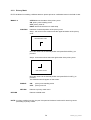
4.1.9 Privacy Mask
EPTZ 100 allows for masking 4 different areas to protect private or confidential zones in the field of view.
MASK1~4
OFF/ON shows the status of the privacy zone:
ON: privacy zone masking active
OFF: privacy zone off
RIGHT enters the submenu to mask setup
POSITION
Definition of size and position of the privacy zone:
Step 1: the corner in the screen marks the upper left border of the privacy
zone:
IRIS OPEN:NEXT STEP
Move the camera to the desired position and press IRIS OPEN (+) to
proceed.
Step 2: next screen shows the lower right border of the privacy zone:
IRIS CLOSE TO EXIT
Move the camera to the desired position and press IRIS CLOSE (-) to
proceed.
The defined mask will appear on the screen.
RETURN
ENABLE
ON:
OFF:
privacy zone masking active
privacy zone off
RETURN
Returns to privacy mask menu.
Returns to MAIN menu.
NOTE: If privacy masking is active, the pan / tilt speed of the dome is reduced for ensuring correct
processing of privacy masks.
36
EPTZ100_ma_en_rev03.doc
4.1.10 Alarm
In this menu, the alarm reactions for input contacts are defined.
RELAY
OFF/ON
It is possible to switch the output relay remotely with
this menu item for test purpose:
ON:
output relay switched
OFF: output relay not active (off)
INPUT1...3
PRESET x
Assignment of the preset position which is linked to
alarm input.
Select preset position 1~32.
OUTPUT
OFF/ON
ON:
the camera will go to preset [assigned preset
position in lines above] in case of alarm.
In case of alarm, the camera moves to the
defined preset and stays there until manual
PTZ control or any programmed AUTO
RESUME function is carried out
OFF: no reaction in case of active alarm input
RETURN
Return to main menu.
4.1.11 Initialize
POWER ON RESET
ON: performs a PTZ initialization similar to power on
OFF: returns to INITIALIZE menu
CAMERA DEFAULT
ON: reset of the camera module to factory settings
OFF: returns to INITIALIZE menu
FACTORY DEFAULT
ON: reset of the pan/tilt electronics module to factory
settings
OFF: returns to INITIALIZE menu
LENS REFRESH x DAYS
OFF,
1...15
Frequent initialization of zoom lens for better stability
and preset precision.
OFF: no frequent initialization
1...15: interval in days for initialization
CAMERA REFRESH x DAYS
OFF,
1...15
Frequent initialization of pan/tilt mechanism for better
stability and preset precision.
OFF: no frequent initialization
1...15: interval in days for initialization
37
EPTZ100_ma_en_rev03.doc
5 OPERATION WITH EKB 500 KEYBOARD
The following chapter describes the EPTZ 100 operation with EKB 500 keyboard (with firmware 1.5 or
higher).
EPTZ 100 is optimized for protocol type EVF-2 of EKB 500 keyboard.
Basic communication settings for EKB 500 are described in APPENDIX A.
For further details, please refer to the EKB 500 user manual.
The following operating elements are available for EPTZ 100 PTZ control:
General key description:
IIIR
S
R
RIIIS
S +++ /// ---:::
F
O
C
N
F
S
U
F
N...:::
F... /// N
SF
US
FO
OC
CU
Z
O
O
Z
M
N
O
U
T
M IIIN
OM
ZO
OO
N /// O
OU
UT
T:
P
P
O
S
T
O
N
PO
OS
SIIIT
TIIIO
ON
N:
T
T
O
U
R
TO
OU
UR
R:
A
.
P
A
N
A
A..P
PA
AN
N:
H
H
O
M
E
HO
OM
ME
E:
F
F
F444:
M
M
E
N
U
ME
EN
NU
U:::
S
H
I
F
T
S
SH
HIIF
FT
T:
manual iris control, + opens iris, - closes iris
manual focus, F. TELE; N. WIDE
zoom keys, same function as joystick rotation, IN = TELE, OUT = WIDE
start and save positions
start preset tours and pattern tours
autopan, start and save automatic pan operation
go to home position (preset position 1)
remote switching of EPTZ 100 output relay
opens EPTZ 100 OSD setup menu
switch key for second key level (depending on function)
38
EPTZ100_ma_en_rev03.doc
5.1
EKB 500 OPERATION WITH EVERFOCUS PROTOCOL (EVF-2)
Operation outline
Function
Keys / operation
Open dome menu
M
M
E
N
U
C
A
M
M
E
N
U
ME
EN
NU
U or C
CA
AM
M (hold) + M
ME
EN
NU
U (if main monitor of DVR is selected)
or S
S
H
F
T
P
O
S
T
O
N
SH
HIIIF
FT
T (hold)+ P
PO
OS
SIIIT
TIIIO
ON
N >>> 999555
Switch menu functions
JJJO
O
Y
S
T
C
K
OY
YS
ST
TIIIC
CK
K
JJJO
Y
S
T
I
C
K
O
Y
S
T
I
C
K
OYSTICK
Change menu settings
Leave dome menu
Pan/tilt
C
C
R
M
E
N
U
E
N
T
E
R
CLLLR
R (hold) + M
ME
EN
NU
U or menu item EXIT > E
EN
NT
TE
ER
R
JJJO
Y
S
T
I
C
K
O
OY
YS
ST
TIIC
CK
K
Zoom TELE / WIDE
TELE: Z
Z
O
O
M
N
O
Y
S
T
C
K
ZO
OO
OM
M IIIN
N or JJJO
OY
YS
ST
TIIIC
CK
K rotation to the right
WIDE: Z
Z
O
O
M
O
U
T
O
Y
S
T
C
K
ZO
OO
OM
MO
OU
UT
T or JJJO
OY
YS
ST
TIIIC
CK
K rotation to the left
Focus
Iris open / close
TELE: F
F
O
C
U
S
F
F
O
C
U
S
N
FO
OC
CU
US
SF
F... ; WIDE: F
FO
OC
CU
US
SN
N...
Open iris: IIIR
R
S
R
S
RIIIS
S +++ / close iris: IIIR
RIIIS
S ---...
Go to position (preset)
Preset number + P
P
O
S
T
O
N
P
O
S
T
O
N
E
N
T
E
R
PO
OS
SIIIT
TIIIO
ON
N/ P
PO
OS
SIIIT
TIIIO
ON
N + preset number > E
EN
NT
TE
ER
R
Save position (preset)
S
S
H
F
T
P
O
S
T
O
N
E
N
T
E
R
SH
HIIIF
FT
T (hold) + P
PO
OS
SIIIT
TIIIO
ON
N > preset number > E
EN
NT
TE
ER
R
C
C
R
P
O
S
T
O
N
E
N
T
E
R
CLLLR
R (hold) + P
PO
OS
SIIIT
TIIIO
ON
N > preset number > E
EN
NT
TE
ER
R
Delete preset
Start patrol tour
Start all preset tour
Start preset tour Group 1
Start preset tour Group 2
Start preset tour Group 3
Start preset tour Group 4
Start preset Tour Scan
Start pattern 1
Start pattern 2
Start pattern 3
Start pattern 4
Start autopan
T
T
O
U
R
E
N
T
E
R
TO
OU
UR
R > 111 > E
EN
NT
TE
ER
R
T
O
U
R
>
2
>
E
N
T
E
R
T
O
U
R
2
E
N
T
E
R
TOUR 2 ENTER
T
T
O
U
R
E
N
T
E
R
TO
OU
UR
R > 333 > E
EN
NT
TE
ER
R
T
O
U
R
>
4
>
E
N
T
E
R
T
TO
OU
UR
R 44 E
EN
NT
TE
ER
R
T
T
O
U
R
E
N
T
E
R
TO
OU
UR
R > 555 > E
EN
NT
TE
ER
R
T
O
U
R
>
6
>
E
N
T
E
R
T
TO
OU
UR
R 66 E
EN
NT
TE
ER
R
T
T
O
U
R
E
N
T
E
R
TO
OU
UR
R > 777 > E
EN
NT
TE
ER
R
T
T
O
U
R
E
N
T
E
R
TO
OU
UR
R > 111777 > E
EN
NT
TE
ER
R
T
T
O
U
R
E
N
T
E
R
TO
OU
UR
R > 111888 > E
EN
NT
TE
ER
R
T
T
O
U
R
E
N
T
E
R
TO
OU
UR
R > 111999 > E
EN
NT
TE
ER
R
T
T
O
U
R
E
N
T
E
R
TO
OU
UR
R > 222000 > E
EN
NT
TE
ER
R
A
A
P
A
N
A...P
PA
AN
N > speed [enter any value, the speed is defined in OSD
menu]> E
E
N
T
E
R
EN
NT
TE
ER
R
360° autopan
S
S
H
F
T
A
P
A
N
SH
HIIIF
FT
T (hold) + A
A...P
PA
AN
N > speed [enter any value, the speed is
defined in OSD menu]> E
E
N
T
E
R
EN
NT
TE
ER
R
Start home position
H
H
O
M
E
HO
OM
ME
E
F
F
E
N
T
E
R
F444 >>> 111 >>> E
EN
NT
TE
ER
R
Switch ON output relay
Switch OFF output relay
PTZ - Initialization
C
C
R
F
E
N
T
E
R
CLLLR
R +++ F
F444 >>> 111 >>> E
EN
NT
TE
ER
R
P
P
O
S
T
O
N
E
N
T
E
R
PO
OS
SIIIT
TIIIO
ON
N > 888000 > E
EN
NT
TE
ER
R
39
EPTZ100_ma_en_rev03.doc
5.1.1 EPTZ 100 setup menu
Start EPTZ menu:
If DVR Main monitor is selected ("DVR" in LCD display):
C
C
A
M
M
E
N
U
CA
AM
M (hold) + M
ME
EN
NU
U
If no DVR main monitor is selected:
M
M
E
N
U
C
A
M
M
E
N
U
ME
EN
NU
U or C
CA
AM
M (hold) + M
ME
EN
NU
U
or alternatively in both modes:
S
S
H
F
T
P
R
E
S
E
T
E
N
T
E
R
SH
HIIIF
FT
T (hold) + P
PR
RE
ES
SE
ET
T > 999 555 > E
EN
NT
TE
ER
R
Switch between the settings:
JJJO
O
Y
S
T
C
K
OY
YS
ST
TIIIC
CK
K
Enter submenus:
JJJO
O
Y
S
T
C
K
OY
YS
ST
TIIIC
CK
K
in CAMERA > ADVANCED SETUP: IIIR
R
S
RIIIS
S +++
Change the settings:
JJJO
O
Y
S
T
C
K
OY
YS
ST
TIIIC
CK
K
EXIT OSD menu / submenus:
Menu item EXIT/RETURN > JJJO
O
Y
S
T
C
K
OY
YS
ST
TIIIC
CK
K
in CAMERA > ADVANCED SETUP: IIIR
R
S
RIIIS
S ---
Note: Exceptional commands are described in the OSD.
5.1.2 Preset positions
Up to 64 preset PTZ positions can be stored in EPTZ 100.
Save presets
S
S
H
F
T
P
O
S
T
O
N
SH
HIIIF
FT
T (hold) + P
PO
OS
SIIIT
TIIIO
ON
N
> [ preset number ] > E
E
N
T
E
R
EN
NT
TE
ER
R
Camera:0001 Save to
Position:___[1-192]
Delete preset
Camera:0001
Del Position:___
C
C
R
P
O
S
T
O
N
CLLLR
R (hold) + P
PO
OS
SIIIT
TIIIO
ON
N
> [ preset number ] > E
N
E
N
T
E
R
ENT
TE
ER
R
Start (go to) preset
Camera:0001 go to
Position:___[1-192]
P
P
O
S
T
O
N
E
N
T
E
R
PO
OS
SIIIT
TIIIO
ON
N > [ preset number ] > E
EN
NT
TE
ER
R
5.1.3 Autopan
The speed for autopan function is programmed in OSD menu; the entered value for speed in EKB 500 will
be ignored at start of autopan.
Activate A-B autopan (pan between 2 points)
A
A
P
A
N
E
N
T
E
R
A...P
PA
AN
N > any value 111~~~ 222333999 > E
EN
NT
TE
ER
R
Speed:___[1-239]
[ENT] to start.
Activate 360° autopan
S
S
H
F
T
A
P
A
N
E
N
T
E
R
SH
HIIIF
FT
T (hold) + A
A...P
PA
AN
N > any value 111~~~ 222333999 > E
EN
NT
TE
ER
R
40
EPTZ100_ma_en_rev03.doc
5.1.4 Preset tours
EPTZ 100 provides 7 different preset tour modes. All tours are defined in OSD setup menu.
1.
2.
3.
4.
5.
6.
7.
PATROL TOUR:
ALL PRESET TOUR:
GROUP 1 TOUR:
GROUP 2 TOUR:
GROUP 3 TOUR:
GROUP 4 TOUR:
TOUR SCAN:
Preset tour with up to 16 selected presets.
Preset tour with all available presets.
Preset tour with presets 1~4
Preset tour with presets 1~4
Preset tour with presets 1~4
Preset tour with presets 1~4
Preset tour with defined preset GROUPS
T
T
O
U
R
E
N
T
E
R
TO
OU
UR
R > [tour number 1...7] > E
EN
NT
TE
ER
R
Tour numbers:
[1]
[2]
[3]
[4]
[5]
[6]
[7]
Camera:0001
Run Tour:__[1-16]
PATROL TOUR
ALL PRESET TOUR
GROUP 1 TOUR
GROUP 2 TOUR
GROUP 3 TOUR
GROUP 4 TOUR
TOUR SCAN
Alternative for ALL PRESET TOUR:
P
P
O
S
T
O
N
E
N
T
E
R
PO
OS
SIIIT
TIIIO
ON
N > 999999 > E
EN
NT
TE
ER
R
5.1.5 Pattern tours
EPTZ 100 provides 4 programmed pattern tours with up to 10 minutes duration each.
The pattern tours are started with the T
T
O
U
R
TO
OU
UR
R key.
T
T
O
U
R
E
N
T
E
R
TO
OU
UR
R > [tour number 17...20] > E
EN
NT
TE
ER
R
Tour numbers:
[17]
[18]
[19]
[20]
Camera:0001
Run Tour:__[1-16]
Pattern 1
Pattern 2
Pattern 3
Pattern 4
5.1.6 Remote switching of EPTZ 100 output relay
The EKB 500 keyboard provides the option to switch the output relay of EPTZ 100 on / off.
Switch relay ON:
F
F
E
N
T
E
R
F444 >>> [[[111]]] >>> E
EN
NT
TE
ER
R
Switch Alarm Out: _
[ 1-8] ON
Alternative:
P
P
O
S
T
O
N
E
N
T
E
R
PO
OS
SIIIT
TIIIO
ON
N > 888222 > E
EN
NT
TE
ER
R
Switch relay OFF:
Switch Alarm Out: _
[ 1-8] OFF
C
C
R
F
E
N
T
E
R
CLLLR
R +++ F
F444 >>> [[[111]]] >>> E
EN
NT
TE
ER
R
Alternative:
P
P
O
S
T
O
N
E
N
T
E
R
PO
OS
SIIIT
TIIIO
ON
N > 888111 > E
EN
NT
TE
ER
R
41
EPTZ100_ma_en_rev03.doc
5.2
EKB 500 OPERATION WITH PELCO-D/P PROTOCOL
NOTE: Not all EPTZ 100 functions are available in PELCO-D/P protocol. Operation for ssome functions is
different to operation with EVERFOCUS protocol.
5.2.1 EPTZ 100 setup menu
Start EPTZ 100 menu:
If DVR Main monitor is selected ("DVR" in LCD display):
C
C
A
M
M
E
N
U
CA
AM
M (hold) + M
ME
EN
NU
U
If no DVR main monitor is selected:
M
M
E
N
U
C
A
M
M
E
N
U
ME
EN
NU
U or C
CA
AM
M (hold) + M
ME
EN
NU
U
or alternatively in both modes:
S
S
H
F
T
P
R
E
S
E
T
E
N
T
E
R
SH
HIIIF
FT
T (hold) + P
PR
RE
ES
SE
ET
T > 999 555 > E
EN
NT
TE
ER
R
Switch between the settings:
JJJO
O
Y
S
T
C
K
OY
YS
ST
TIIIC
CK
K
Enter submenus:
JJJO
O
Y
S
T
C
K
OY
YS
ST
TIIIC
CK
K
in CAMERA ADVANCED SETUP: IIIR
R
S
RIIIS
S +++
Change the settings:
JJJO
O
Y
S
T
C
K
OY
YS
ST
TIIIC
CK
K
EXIT OSD menu / submenus:
Menu item EXIT/RETURN > JJJO
O
Y
S
T
C
K
OY
YS
ST
TIIIC
CK
K
in CAMERA ADVANCED SETUP: IIIR
R
S
RIIIS
S ---
Note: Exceptional commands are described in the OSD.
5.2.2 Preset positions
Up to 64 preset PTZ positions can be stored in EPTZ 100.
Save presets
S
S
H
F
T
P
O
S
T
O
N
SH
HIIIF
FT
T (hold) + P
PO
OS
SIIIT
TIIIO
ON
N
> [ preset number ] > E
E
N
T
E
R
EN
NT
TE
ER
R
Camera:0001 Save to
Position:___[1-192]
Delete preset
Camera:0001
Del Position:___
C
C
R
P
O
S
T
O
N
CLLLR
R (hold) + P
PO
OS
SIIIT
TIIIO
ON
N
> [ preset number ] > E
N
E
N
T
E
R
ENT
TE
ER
R
Start (go to) preset
Camera:0001 go to
Position:___[1-192]
P
P
O
S
T
O
N
E
N
T
E
R
PO
OS
SIIIT
TIIIO
ON
N > [ preset number ] > E
EN
NT
TE
ER
R
42
EPTZ100_ma_en_rev03.doc
5.2.3 Autopan
The speed for autopan function is programmed in the OSD menu; the entered value for speed in EKB 500
will be ignored at start of autopan.
Activate A-B autopan (pan/tilt between 2 points)
A
A
P
A
N
A...P
PA
AN
N (Pelco-P only)
Alternative:
P
P
O
S
T
O
N
E
N
T
E
R
PO
OS
SIIIT
TIIIO
ON
N > 999999 > E
EN
NT
TE
ER
R
5.2.4 Preset tours
EPTZ 100 provides 7 different preset tour modes. All tours are defined in the OSD setup menu.
PATROL TOUR:
ALL PRESET TOUR:
GROUP 1 TOUR:
GROUP 2 TOUR:
GROUP 3 TOUR:
GROUP 4 TOUR:
TOUR SCAN:
Preset tour with up to 16 selected presets.
Preset tour with all available presets.
Preset tour with presets 1~4
Preset tour with presets 1~4
Preset tour with presets 1~4
Preset tour with presets 1~4
Preset tour with defined preset GROUPS
P
P
O
S
T
O
N
E
N
T
E
R
PO
OS
SIIIT
TIIIO
ON
N > [number] > E
EN
NT
TE
ER
R
Tour numbers:
Camera:0001 goto
Position:__[1-192]
[68] TOUR SCAN
[69] PATROL TOUR
[70 or 98] ALL PRESET TOUR
[71] GROUP 1 TOUR
[72] GROUP 2 TOUR
[73] GROUP 3 TOUR
[74] GROUP 4 TOUR
5.2.5 Pattern tours
EPTZ 100 provides 4 programmed pattern tours with up to 10 minutes duration each.
The pattern tours are started with the P
P
O
S
T
O
N
PO
OS
SIIIT
TIIIO
ON
N key.
P
P
O
S
T
O
N
E
N
T
E
R
PO
OS
SIIIT
TIIIO
ON
N > [number] > E
EN
NT
TE
ER
R
Numbers:
[75]
[76]
[77]
[78]
Camera:0001 goto
Position:__[1-192]
Pattern 1
Pattern 2
Pattern 3
Pattern 4
43
EPTZ100_ma_en_rev03.doc
5.2.6 Remote switching of EPTZ 100 output relay
The EKB 500 keyboard provides the option to switch the output relay of EPTZ 100 On / Off.
Switch relay ON:
F
F
E
N
T
E
R
F444 >>> [[[111]]] >>> E
EN
NT
TE
ER
R
Switch Alarm Out: _
[ 1-8] ON
Alternative:
P
P
O
S
T
O
N
E
N
T
E
R
PO
OS
SIIIT
TIIIO
ON
N > 888222 > E
EN
NT
TE
ER
R
Switch relay OFF:
Switch Alarm Out: _
[ 1-8] OFF
C
C
R
F
E
N
T
E
R
CLLLR
R +++ F
F444 >>> [[[111]]] >>> E
EN
NT
TE
ER
R
Alternative:
P
P
O
S
T
O
N
E
N
T
E
R
PO
OS
SIIIT
TIIIO
ON
N > 888111 > E
EN
NT
TE
ER
R
44
EPTZ100_ma_en_rev03.doc
6 APPENDIX A: BASIC SETTINGS AT EKB 500 KEYBOARD
The following chapter describes the basic settings in the EKB 500 keyboard to establish communication
with speed dome cameras.
6.1
COM PORT SETTING - RS-485 INTERFACE SETTING
Telemetry protocol type and transmission rate are defined in this menu.
Port : _ ( 1 or 2 )
Input the port.
M
M
E
N
U
E
N
T
E
R
ME
EN
NU
U > COM PORT SETTING > E
EN
NT
TE
ER
R
Select port 1 or 2 and confirm with E
N
T
E
E
N
T
E
R
ENTER
R.
Use the JJJO
to change the value.
O
Y
S
T
C
K
OY
YS
ST
TIIIC
CK
K
Selection: 1200, 2400, 4800, 9600 Baud.
Press E
E
N
T
E
R
E
S
C
EN
NT
TE
ER
R to confirm the setting and E
ES
SC
C to cancel.
BAUD : 9600 <
[ ↑ ↓ ] to change
The next menu is used for telemetry protocol
Protocol : EVF-2
setting.
[ ↑ ↓ ] to change
Use the JJJO
Y
S
T
I
C
K
to
change
the
value.
O
OY
YS
ST
TIIC
CK
K
Selection:
EVF-2:
recommended protocol for optimized EKB 500 functionality
Pelco-D
Pelco-P
NOTE: Baud rate and protocol type have to comply with the EPTZ 100 settings for these parameters
(DS1 DIP switch setting).
Press E
E
N
T
E
R
E
S
C
EN
NT
TE
ER
R to confirm the selection and E
ES
SC
C to cancel.
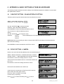
6.2
Port : 1 Changed
[ ENT ] to save
DEVICE SETTING > CAMERA
Define in this menu RS-485 ID (address) and connected RS-485 port:
M
M
E
N
U
E
N
T
E
R
ME
EN
NU
U > DEVICE SETTING > CAMERA SETTING > E
EN
NT
TE
ER
R
Camera number 1 ~ 9999 (independent from RS-485 address!)
Press Enter to confirm the setting and Esc to cancel.
Camera Name : ___
Setup of the RS-485 interface which is connected to EPTZ 100,
port 1 or 2.
Press Enter to confirm the setting and E
E
S
C
ES
SC
C to cancel.
RS485 Connected to
Port : _ [ 0 (off) ] , 1, 2]
RS485 Address:
001
Enter the RS-485 address of the EPTZ 100.
If the camera is connected to an EverFocus DVR, enter the
DVR number and video input number.
Enter any value if no DVR is connected
(numeric entry compulsory).
Press E
E
N
T
E
R
E
S
C
EN
NT
TE
ER
R to confirm the setting and E
ES
SC
C to cancel.
45
Video Connected to
DVR: _ _ _ CH : _ _
Camera: 0001 changed
[ENT] to save
EPTZ100_ma_en_rev03.doc
7 APPENDIX B: BASIC SETTINGS AT EVERFOCUS DVR
The following settings are required to establish RS-485 communication between DVR and speed dome:
7.1
EDR / EDVR / EDSR SERIES (EXCEPT EDSR100, EDSR100H)
1. CAMERA menu: enter the correct RS-485 ID (address) at the speed dome camera channel.
2. CONTROL menu: under "RS485" :
BAUD RATE:
PARITY:
DATA BIT:
STOP BIT:
PROTOCOL:
set value identical to camera baud rate
NONE
8
1
set protocol identical to speed dome protocol
NOTE: The RS-485 ID in CONTROL menu is not related to speed dome control. This RS-485 ID is used
for controlling DVR by external keyboard only.
7.2
ECOR / PARAGON SERIES
1. CAMERA menu: enter the correct RS-485 ID (address) at the speed dome camera channel.
2. SYSTEM > I/O CONTROL menu:
BAUD RATE:
PARITY:
DATA BIT:
STOP BIT:
PROTOCOL:
set value identical to camera baud rate
NONE
8
1
set protocol identical to speed dome protocol
NOTE: The RS-485 ID in menu I/O CONTROL menu is not related to speed dome control. This RS-485
ID is used for controlling DVR by external keyboard only.
46
EPTZ100_ma_en_rev03.doc
8 APPENDIX C: TROUBLESHOOTING
8.1
GENERAL MALFUNCTION
In case of drifted preset position or abnormal reaction of EPTZ 100 speed dome perform a reset of the dome, for the reset 3
options are possible:
Option 1:
Setup menu > INITIALIZE > POWER ON RESET
Option 2:
(GoTo) POSITION 80
Option 3:
Power off dome for min. 5 seconds, then power on
8.2
RECOVERING COMMUNICATION SETTINGS OF CAMERA MODULE
If the camera communication settings in the setup menu CAMERA > ADVANCED SETUP > SPECIAL > COMM ADJ were changed
accidentally, the communication between Speed Dome and camera module may be broken.
Symptoms:
a) Pan / Tilt works, but no zoom function
b) OSD setup works, but no access to the submenu CAMERA > ADVANCED SETUP
Correction:
Step 1: Go in setup menu to INITIALIZE > CAMERA DEFAULT > ON and perform a camera reset. If this reset works, all settings
from ADVANCED SETTING menu will be reset to factory defaults.
Check access to menu ADVANCED SETUP. If the submenu opens, the communication error is fixed.
If the problem still exists, go to STEP 2.
Step 2:
Go in setup menu to CAMERA > RESCUE MODE > set to ON
The values for BAUD RATE and PARITY will appear.
Change values for BAUD RATE and try with each changed value access to ADVANCED SETUP menu. Check also with
PARITY setting ODD/EVEN.
With correct settings access to ADVANCED SETUP is possible, the submenu appears additional
to the camera menu on the screen:
Switch off the CAMERA menu display by pressing IRIS + key.
Go to > SPECIAL > COMM ADJ and set / verify following default settings:
BAUD RATE
38400
UART MODE
8-N-1
RET PKT ENABLE
EXIT all menus.
Restart the EPTZ-100 with power OFF / ON to finish the camera setting recovery.
47
EPTZ100_ma_en_rev03.doc
EverFocus Electronics Corp.
China Subsidiary:
Room 609, Technology Trade Building,
Shandgdi Information Industry Base,
Haidian District, Beijing,China
www.everfocus.com.cn
Head Office:
12F, No.79 Sec. 1 Shin-Tai Wu Road,
Hsi-Chih, Taipei, Taiwan
www.everfocus.com.tw
USA Subsidiary:
1801 Highland Ave. Unit A
Duarte, CA 91010, U.S.A.
www.everfocus.com
Japan Subsidiary:
1809 WBG MARIBU East 18F,
2-6 Nakase.Mihama-ku.
Chiba city 261-7118, Japan
www.everfocus.com
European Subsidiary:
Albert-Einstein-Straße 1
D-46446 Emmerich am Rhein, Germany
www.everfocus.de
48
EPTZ100_ma_en_rev03.doc