1
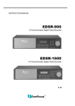
BEDIENUNGSANWEISUNG
---------------------------------------------------------------------------------------------------------------------------------------------------------
OPERATING INSTRUCTIONS
---------------------------------------------------------------------------------------------------------------------------------------------------------
MANUALE D’USO
---------------------------------------------------------------------------------------------------------------------------------------------------------
MANUEL D’INSTRUCTIONS
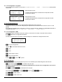
US FCC Part 15 Class B Verification Statement
NOTE: This equipment has been tested and found to comply with the limits for a Class B digital
device, pursuant to Part 15 of the FCC Rules. These limits are designed to provide reasonable
protection against harmful interference in a residential installation. This equipment generates, uses
and can radiate radio frequency energy and, if not installed and used in accordance with the
instructions, may cause harmful interference to radio communications. However, there is no
guarantee that interference will not occur in a particular installation. If this equipment does cause
harmful interference to radio or television reception, which can be determined by turning the
equipment off and on, the user is encouraged to try to correct the interference by one or more of the
following measures:
-- Reorient or relocate the receiving antenna.
-- Increase the separation between the equipment and receiver.
-- Connect the equipment into an outlet on a circuit different from that to which the receiver is connected.
-- Consult the dealer or an experienced radio/TV technician for help.
BEDIENUNGSANWEISUNG
INHALTSVERZEICHNIS
1 ÖFFNUNG DER VERPACKUNG UND INHALTSKONTROLLE..............................................................................6
1.1 Inhalt der Verpackung .........................................................................................................................................6
1.2 Öffnen der Verpackung .......................................................................................................................................6
1.3 Überprüfung der Kennzeichnung ........................................................................................................................6
1.4 Beschreibung der Etiketten .................................................................................................................................6
2 BESCHREIBUNG......................................................................................................................................................7
2.1 Eigenschaften .....................................................................................................................................................7
2.1.1 Tastatur..........................................................................................................................................................................7
2.1.2 Konfiguration..................................................................................................................................................................7
2.1.3 Sicherheit.......................................................................................................................................................................7
2.2 An die Tastatur KS KBJ anschließbare Geräte...................................................................................................7
2.2.1 Digital- Videorecorder ....................................................................................................................................................7
2.2.2 Videomatrix....................................................................................................................................................................7
2.2.3 Video-Multiplexer ...........................................................................................................................................................8
2.2.4 Telemetrieempfänger und Domes..................................................................................................................................8
2.3 Tasten und Steckverbindungen ..........................................................................................................................8
2.4 Zweitfunktionstasten ...........................................................................................................................................9
2.5 Dip switch ............................................................................................................................................................9
3 VERBINDUNGSLEITUNGEN UND ANSCHLÜSSE...............................................................................................10
3.1 Videoleitung und Telemetrieleitungen...............................................................................................................10
3.2 RS485 und Anlagentypen .................................................................................................................................10
3.3 Standard-Anschlußkabel...................................................................................................................................11
3.4 Eine Tastatur je Leitung ....................................................................................................................................12
3.5 Mehr als zwei Einrichtungen an derselben Leitung ..........................................................................................12
4 KONFIGURIERUNG DER TASTATUR ..................................................................................................................13
4.1 Tasten ...............................................................................................................................................................13
4.2 Auswahl und Eingabe von Werten....................................................................................................................13
4.3 Menüoptionen ...................................................................................................................................................13
4.4 Zuordnung der Telemetrieleitungen..................................................................................................................15
4.4.1 Werkseinstellung..........................................................................................................................................................15
4.4.2 Zuordnung aller Empfänger zu einer einzigen Leitung.................................................................................................16
4.4.3 Änderung des Verzeichnisses .....................................................................................................................................16
4.5 Aktivierung für die Ansteuerung der Videokameras .........................................................................................16
4.5.1 Werkseinstellung..........................................................................................................................................................17
4.5.2 Änderung des Verzeichnisses .....................................................................................................................................17
4.5.3 Hinweismeldung...........................................................................................................................................................18
4.6 Freigabe der Monitoransteuerung.....................................................................................................................18
4.6.1 Werkseinstellung..........................................................................................................................................................18
4.6.2 Änderung des Verzeichnisses .....................................................................................................................................18
4.7 Freigabe der Multiplexeransteuerung ...............................................................................................................19
4.7.1 Werkseinstellungen......................................................................................................................................................19
4.7.2 Änderung des Verzeichnisses .....................................................................................................................................19
4.8 Freigabe der Funktionsanwahl..........................................................................................................................19
4.9 Kalibrierung und Joystick- Test .........................................................................................................................20
4.10 Buzzer (Summer) ............................................................................................................................................21
4.11 Passwort..........................................................................................................................................................21
4.12 Hinweis- und Fehlermeldungen ......................................................................................................................21
4.13 Autotest der seriellen Kommunikationskanäle ................................................................................................22
4.13.1 Autotestprozedur........................................................................................................................................................22
4.14 Protokoll Macro: Sonderfunktionen.................................................................................................................23
4.14.1 Beschreibung .............................................................................................................................................................23
4.14.2 Sonderfunktionen für das Protokoll Macro .................................................................................................................23
Seite 1
MNECKSKBJ_0350
5 VIDEOSTEUERUNG ...............................................................................................................................................24
5.1 Beschreibung des Displays...............................................................................................................................24
5.2 Video: Grundkonzepte ......................................................................................................................................24
5.2.1 Direkte Anwahl einer Videokamera..............................................................................................................................24
5.2.2 Auswahl der vorhergehenden / nachfolgenden Kamera ..............................................................................................25
5.2.3 Steuerung von digitalen Videorekordern Everfocus .....................................................................................................25
5.2.4 “Ansichten”...................................................................................................................................................................26
5.2.5 Den Videokameras zugeordnete Empfänger ...............................................................................................................27
5.3 DVR Everfocus..................................................................................................................................................28
5.3.1 Beschreibung...............................................................................................................................................................28
5.3.2 Anschluß......................................................................................................................................................................28
5.3.3 Konfigurieren des DVR ................................................................................................................................................28
5.4 Videomatrix KS VM 328 ....................................................................................................................................29
5.4.1 Beschreibung...............................................................................................................................................................29
5.4.2 Anschluß......................................................................................................................................................................29
5.4.3 Einrichtung der Matrix ..................................................................................................................................................29
5.5 Videomatrix KS VM 164 ....................................................................................................................................30
5.5.1 Anschluß......................................................................................................................................................................30
5.5.2 Einrichtung der Videoeinrichtung .................................................................................................................................30
5.6 Videotec SM42A, Videotec SM82A, Videotec SM84A .....................................................................................31
5.6.1 Anschluß......................................................................................................................................................................31
5.6.2 Einrichtung der Videoeinrichtung .................................................................................................................................31
5.7 Videomatrix Linxs LXRPS84A und Linxs LXRPS164A.....................................................................................32
5.7.1 Beschreibung...............................................................................................................................................................32
5.7.2 Anschluß......................................................................................................................................................................32
5.7.3 Konfiguration der Videoeinrichtung ..............................................................................................................................33
5.8 Umschalter Linxs LXRPS42A und Linxs LXRPS82A Linxs ..............................................................................34
5.8.1 Beschreibung...............................................................................................................................................................34
5.8.2 Anschluß......................................................................................................................................................................34
5.8.3 Konfiguration der Videoeinrichtung ..............................................................................................................................35
5.9 Videomatrix Videotec SW164OSM ...................................................................................................................36
5.9.1 Beschreibung...............................................................................................................................................................36
5.9.2 Anschluß......................................................................................................................................................................36
5.9.3 Einrichtung der Matrix ..................................................................................................................................................38
5.10 Video-Multiplexer Javelin / Hitron ...................................................................................................................39
5.10.1 Direktverbindung........................................................................................................................................................39
5.10.2 Dedizierte Funktionen ................................................................................................................................................40
5.11 Video-Multiplexer Videotec SP16C.................................................................................................................41
5.11.1 Beschreibung .............................................................................................................................................................41
5.11.2 Direktverbindung........................................................................................................................................................41
5.11.3 Dedizierte Funktionen ................................................................................................................................................42
5.12 Steuerung des Multiplexers mit einer Videoeinrichtung..................................................................................43
5.12.1 Auswahl eines mit der Videomatrix verbundenen Monitors .......................................................................................43
5.12.2 Auswahl eines mit dem Multiplexer verbundenen Monitors .......................................................................................43
5.13 Video-Multiplexer Sony ...................................................................................................................................44
5.13.1 Beschreibung .............................................................................................................................................................44
5.13.2 Verweis auf weitere Materialien und Dokumente .......................................................................................................44
5.13.3 Direktverbindung........................................................................................................................................................44
5.13.4 Konfiguration..............................................................................................................................................................45
5.13.5 Sonderfunktionen.......................................................................................................................................................45
5.14 DVR Sony........................................................................................................................................................47
5.14.1 Beschreibung .............................................................................................................................................................47
5.14.2 Verweis auf weitere Materialien und Dokumente .......................................................................................................47
5.14.3 Direktverbindung........................................................................................................................................................47
5.14.4 Konfiguration..............................................................................................................................................................48
5.14.5 Sondermenü SEARCH ..............................................................................................................................................48
5.14.6 Sondermenü COPY ...................................................................................................................................................48
5.14.7 Sonderfunktionen.......................................................................................................................................................48
5.15 Multiplexer Ademco.........................................................................................................................................50
5.15.1 Beschreibung .............................................................................................................................................................50
5.15.2 Direktverbindung........................................................................................................................................................50
5.15.3 Sonderfunktionen.......................................................................................................................................................51
Seite 2
MNECKSKBJ_0350
5.16 Multiplexer Sanyo............................................................................................................................................52
5.16.1 Beschreibung .............................................................................................................................................................52
5.16.2 Verweis auf weitere Materialien und Dokumente .......................................................................................................52
5.16.3 Direktverbindung........................................................................................................................................................52
5.16.4 Konfiguration..............................................................................................................................................................53
5.16.5 Sonderfunktionen.......................................................................................................................................................53
5.16.6 Wahl des Protokolles .................................................................................................................................................54
5.16.7 Displayanzeigen.........................................................................................................................................................54
6 TELEMETRIESTEUERUNG ...................................................................................................................................55
6.1 Telemetriesteuerung direkt und über Videoanlagen .........................................................................................55
6.2 Normale Steuerung der Telemetriebefehle.......................................................................................................56
6.2.1 Wechsel des aktiven Empfängers................................................................................................................................56
6.3 Kommunikationsprobleme zwischen Tastatur und Empfänger.........................................................................56
6.4 Anmerkungen zur Telemetriesteuerung............................................................................................................57
6.4.1 Spezialcodes ...............................................................................................................................................................57
6.4.2 Typografische Schreibweisen ......................................................................................................................................57
6.5 Dome Elbex.......................................................................................................................................................58
6.5.1 Verweis auf weitere Materialien und Dokumente .........................................................................................................58
6.5.2 Wichtige Anmerkung zu den Protokollen .....................................................................................................................58
6.5.3 Anschluß......................................................................................................................................................................58
6.5.4 Konfiguration der Domekamera ...................................................................................................................................58
6.5.5 Steuerung der Domekamera........................................................................................................................................59
6.5.6 Bewegung der Dome ...................................................................................................................................................59
6.5.7 Autopan .......................................................................................................................................................................59
6.5.8 Bewegungsendpunkte .................................................................................................................................................59
6.5.9 Preset, scan, home ......................................................................................................................................................60
6.5.10 Auto scan control .......................................................................................................................................................60
6.5.11 Timer-Funktionen.......................................................................................................................................................61
6.5.12 Optiken ......................................................................................................................................................................61
6.5.13 Hilfsrelais ...................................................................................................................................................................64
6.5.14 Sonstige Funktionen ..................................................................................................................................................64
6.6 Domekamera Elmo ...........................................................................................................................................65
6.6.1 Verweis auf andere Materialien und Dokumente .........................................................................................................65
6.6.2 Anschluß......................................................................................................................................................................65
6.6.3 Konfiguration................................................................................................................................................................65
6.6.4 Autopan .......................................................................................................................................................................67
6.6.5 Preset, scan, home ......................................................................................................................................................67
6.6.6 Sequenzen und Cruise ................................................................................................................................................67
6.6.7 Sonstige Funktionen ....................................................................................................................................................67
6.7 Domekamera Ernitec Saturn.............................................................................................................................68
6.7.1 Verweis auf andere Materialien und Dokumente .........................................................................................................68
6.7.2 Anschluß......................................................................................................................................................................68
6.7.3 Konfiguration................................................................................................................................................................68
6.7.4 Autopan .......................................................................................................................................................................69
6.7.5 Preset, scan, Patrol e home.........................................................................................................................................69
6.7.6 Hilfsrelais .....................................................................................................................................................................70
6.7.7 Optiken ........................................................................................................................................................................70
6.7.8 Rückkehrposition .........................................................................................................................................................70
6.7.9 Sonstige Spezialcodes.................................................................................................................................................70
6.8 Domekamera Hitron Fastrax II ..........................................................................................................................71
6.8.1 Verweis auf andere Materialien und Dokumente .........................................................................................................71
6.8.2 Anschluß......................................................................................................................................................................71
6.8.3 Konfiguration................................................................................................................................................................71
6.8.4 Preset, scan, home ......................................................................................................................................................72
6.8.5 Autoscan, Patrol und Pattern .......................................................................................................................................72
6.9 Domekamera JVC TK-C675 .............................................................................................................................73
6.9.1 Verweis auf andere Materialien und Dokumente .........................................................................................................73
6.9.2 Anschluß......................................................................................................................................................................73
6.9.3 Konfigurierung .............................................................................................................................................................73
6.9.4 Autopan .......................................................................................................................................................................74
6.9.5 Preset, home, scan ......................................................................................................................................................74
6.9.6 Patrol ...........................................................................................................................................................................75
6.9.7 Sonstige Befehle und Spezialcodes.............................................................................................................................75
Seite 3
MNECKSKBJ_0350
6.10 Domekamera JVC TK-C676 ...........................................................................................................................76
6.10.1 Material- und Dokumente- Hinweis ............................................................................................................................76
6.10.2 Hardware-Verbindung des Domes.............................................................................................................................76
6.10.3 Dome- Einstellungen..................................................................................................................................................76
6.10.4 Konfigurierung............................................................................................................................................................76
6.10.5 Hinzufügte Funktionen im Vergleich zum TK-C675- Modell.......................................................................................76
6.10.6 Preset, home, scan ....................................................................................................................................................76
6.10.7 Hilfskontakte ..............................................................................................................................................................76
6.10.8 Andere Funktionen.....................................................................................................................................................77
6.10.9 Zoom e focus .............................................................................................................................................................77
6.11 Domekamera Panasonic.................................................................................................................................78
6.11.1 Verweis auf andere Materialien und Dokumente .......................................................................................................78
6.11.2 Wichtige Anmerkungen zu den Protokollen ...............................................................................................................78
6.11.3 Anschluß....................................................................................................................................................................78
6.11.4 Konfigurierung............................................................................................................................................................79
6.11.5 Autopan .....................................................................................................................................................................79
6.11.6 Autopan-Funktionen für das Modell WV-CS850 ........................................................................................................79
6.11.7 Begrenzung des Bewegungsbereichs beim Modell WV-CS850 ................................................................................79
6.11.8 Preset, scan, home ....................................................................................................................................................80
6.11.9 Konfigurierung Patrol beim Modell WV-CS850 ..........................................................................................................80
6.11.10 Konfigurierung Patrol beim Modell WV-CS600 ........................................................................................................80
6.11.11 Konfigurierung Shutter und Electronic sensitivity .....................................................................................................80
6.11.12 Autoflip.....................................................................................................................................................................81
6.11.13 Optiken und Flip.......................................................................................................................................................81
6.11.14 Relais (nur Modell WV-CS850) ................................................................................................................................81
6.11.15 Sonstige Funktionen (nur Modell WV-CS850) .........................................................................................................82
6.12 Domekamera Pelco.........................................................................................................................................83
6.12.1 Verweis auf andere Materialien und Dokumente .......................................................................................................83
6.12.2 Anschluß....................................................................................................................................................................83
6.12.3 Konfigurierung............................................................................................................................................................83
6.12.4 Preset, scan, home ....................................................................................................................................................83
6.12.5 Pattern .......................................................................................................................................................................84
6.12.6 Zone...........................................................................................................................................................................84
6.12.7 Optiken ......................................................................................................................................................................84
6.12.8 Relais und Alarme......................................................................................................................................................84
6.12.9 Sonstige Funktionen ..................................................................................................................................................85
6.12.10 Geschwindigkeitsstufen ...........................................................................................................................................85
6.13 Domekamera Samsung ..................................................................................................................................86
6.13.1 Verweis auf andere Materialien und Dokumente .......................................................................................................86
6.13.2 Anschluß....................................................................................................................................................................86
6.13.3 Konfigurierung............................................................................................................................................................86
6.13.4 Autopan .....................................................................................................................................................................87
6.13.5 Preset, scan, home, Patrol.........................................................................................................................................87
6.13.6 Pattern .......................................................................................................................................................................88
6.13.7 Sonstige Funktionen ..................................................................................................................................................88
6.14 Domekamera Santec ......................................................................................................................................89
6.14.1 Anschluß....................................................................................................................................................................89
6.14.2 Konfiguration..............................................................................................................................................................89
6.14.3 Preset, scan, home ....................................................................................................................................................90
6.14.4 Autoscan, Patrol und Pattern .....................................................................................................................................90
6.15 Domekamera Sensormatic / American Dynamics ..........................................................................................91
6.15.1 Verweis auf andere Materialien und Dokumente .......................................................................................................91
6.15.2 Anschluß....................................................................................................................................................................91
6.15.3 Konfigurierung............................................................................................................................................................91
6.15.4 Preset, scan, home ....................................................................................................................................................92
6.15.5 Pattern e “apple peel” ................................................................................................................................................92
6.15.6 Relais.........................................................................................................................................................................92
6.15.7 Sonstige Funktionen ..................................................................................................................................................93
6.16 Domekamera Star ...........................................................................................................................................94
6.16.1 Verweis auf andere Materialien und Dokumente .......................................................................................................94
6.16.2 Anschluß....................................................................................................................................................................94
6.16.3 Preset, scan, home ....................................................................................................................................................94
6.16.4 Autopan, Patrol, tour ..................................................................................................................................................94
6.16.5 Konfigurierung............................................................................................................................................................97
Seite 4
MNECKSKBJ_0350
6.16.6 Sonstige Funktionen ..................................................................................................................................................97
6.17 Domekamera VCL...........................................................................................................................................98
6.17.1 Verweis auf andere Materialien und Dokumente .......................................................................................................98
6.17.2 Anschluß....................................................................................................................................................................98
6.17.3 Setup .........................................................................................................................................................................98
6.17.4 Preset, scan, home ....................................................................................................................................................98
6.17.5 Autopan und tour .......................................................................................................................................................98
6.17.6 Kameraeinrichtung.....................................................................................................................................................99
6.17.7 Optiken ....................................................................................................................................................................100
6.17.8 Sonstige Funktionen ................................................................................................................................................100
6.18 Empfänger Everfocus, Videotec und Linxs ...................................................................................................101
6.19 Empfänger Everfocus, Videotec und Linxs mit Protokoll Videotec ...............................................................102
6.19.1 Verweis auf andere Materialien und Dokumente .....................................................................................................102
6.19.2 Anschluß..................................................................................................................................................................102
6.19.3 Preset, scan, home ..................................................................................................................................................102
6.19.4 Autopan ...................................................................................................................................................................102
6.19.5 Patrol .......................................................................................................................................................................103
6.19.6 Relais.......................................................................................................................................................................103
6.19.7 Sonstige Funktionen ................................................................................................................................................103
6.20 Empfänger Everfocus und Videotec mit Protokoll Macro .............................................................................104
6.20.1 Anmerkungen ..........................................................................................................................................................104
6.20.2 Verweis auf andere Materialien und Dokumente .....................................................................................................104
6.20.3 Anschluß..................................................................................................................................................................104
6.20.4 Konfigurierung..........................................................................................................................................................104
6.20.5 Autopan ...................................................................................................................................................................104
6.20.6 Preset, scan, home ..................................................................................................................................................104
6.20.7 Patrol .......................................................................................................................................................................105
6.20.8 Relais.......................................................................................................................................................................106
6.20.9 Optiken ....................................................................................................................................................................106
6.20.10 Sonstige Funktionen ..............................................................................................................................................106
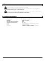
7 WARTUNG ............................................................................................................................................................107
8 TECHNISCHE EIGENSCHAFTEN .......................................................................................................................107
Der Hersteller lehnt jede Verantwortung für Schäden ab, die auf den unsachgemäßen Gebrauch der in diesem
Handbuch genannten Apparate zurückzuführen sind. Er behält sich außerdem das Recht vor, den Inhalt des
Handbuches ohne Vorankündigung zu ändern. Die in diesem Handbuch enthaltene Dokumentation wurde mit
aller nur erdenklichen Sorgfalt zusammengetragen und geprüft. Dennoch kann der Hersteller keine Haftung für
die Nutzung der Dokumentation übernehmen. Das gleiche gilt für die Personen oder Firmen, die an der
Erstellung und Herstellung dieses Handbuches mitgewirkt haben.
Seite 5
MNECKSKBJ_0350
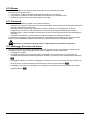
1 Öffnung d er Verpackung und Inhaltskontrolle
Die folgenden Schritte sind, falls nicht anderslautende Angaben dem entgegenstehen, ohne
Stromversorgung des Gerätes durchzuführen.
Die Installation darf nur von technisch versierten Fachleuten vorgenommen werden.
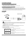
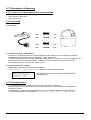
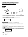
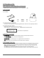
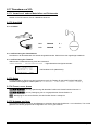
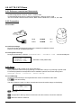
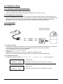
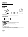
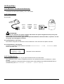
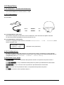
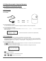
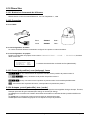
1.1 Inhalt der Verpackung
Bei der Anlieferung des Produktes ist zu prüfen, ob die Verpackung intakt ist und keine deutlichen Sturzspuren
oder Abschabungen aufweist. Falls die Verpackung beschädigt ist, muß dies sofort dem Lieferanten mitgeteilt
werden.
• 1 Tastatur KS KBJ
• 1 externes Netzteil
• 6 Telefonkabel 6/6 gerade gerade, Länge ca. 150 cm
• 6 Abzweigkästen RJjack
• dieses Betriebshandbuch.
Kontrollieren Sie, ob der Inhalt mit der obigen Materialliste übereinstimmt.
1.2 Öffnen de r Verpackung
Weist die Verpackung keine offensichtlichen Anzeichen für Stürze oder starke Abschabungen auf, kann anhand
der Liste im vorangegangenen Abschnitt ihr Inhalt überprüft werden.
Es ist Sache des Installationstechnikers, die Verpackungsstoffe materialgerecht zu sortieren und nach den
geltenden Landesvorschriften zu entsorgen.
1.3 Überprüfu ng der Kennzeichnung
Vor Beginn der Installationsarbeiten ist zu kontrollieren, ob das gelieferte Material den jeweiligen
Anforderungen entspricht. Zu erkennen ist dies anhand des Kennzeichnungsetiketts, wie im nächsten Abschnitt
beschrieben. Unter keinen Umständen dürfen Änderungen oder Anschlüsse vorgenommen werden, die in
diesem Handbuch nicht genannt sind: Der Gebrauch ungeeigneten Gerätes kann eine schwere Gefahr für die
Sicherheit des Personals und der Anlage bedeuten.
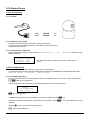
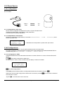
1.4 Beschreib ung der Etiketten
Auf dem Boden der KS KBJ befindet sich ein Etikett, das der CE-Kennzeichnung entspricht.
Es enthält den Identifikationscode (Strichcode EXT3/9 ) und die Seriennummer des Modells (Strichcode
EXT3/9).
Auf dem mitgelieferten Netzteil sitzt ein Etikett mit den Stromversorgungsmerkmalen der Tastatur.
Bei der Installation ist zu kontrollieren, ob die Stromversorgungsmerkmale der Tastatur mit diesen Werten
übereinstimmen. Der Gebrauch ungeeigneten Gerätes kann die Sicherheit des Personals und der Anlage stark
gefährden.
Seite 6
MNECKSKBJ_0350
2 Beschreib ung
2.1 Eigensch aften
Die Tastatur KS KBJ ist ein professionelles Produkt für Anwendungen im Sicherheits- und
Überwachungsbereich.
In einem Sicherheitssystem ermöglicht die Tastatur die Steuerung der Videoumschaltung, die Verwaltung von
Alarmzuständen und die Fernsteuerung von Empfängern digitaler Steuerbefehle.
2.1.1 Tastatur
LCD-Display, rückwärtig beleuchtet, 20 Stellen mal 4 Zeilen für die Steuerung der Vorgänge
Ergonomische Tastenanordnung
Leichte Bedienung: die häufigsten Vorgänge werden mit einer Einzeltaste aktiviert
Telemetriekontrolle mittels Joystick
2.1.2 Konfigurati on
Komplette Einrichtung der Tastatur am Bildschirm
Auswahl der Landessprache
Steuerung einer großen Bandbreite von Empfängern und Hochgeschwindigkeits-Domekameras
Freigabe/Sperrung der Ein- und Ausgänge von jeder Tastatur aus steuerbar
Freigabe/Sperrung von Tastengruppen
Autotest der Kommunikationskanäle
Kommunikationsleitungen RS485
2.1.3 Sicherheit
Buzzer bei Unterbrechung der Verbindungen und bei Alarm
3 Passwortstufen, einzeln für jede Tastatur einrichtbar:
• Passwort für Verbindung: wird beim Einschalten der Tastatur abgefragt, um die Benutzung durch unbefugtes
Personal zu verhindern;
• Passwort für Alarmreset: Passwortabfrage beim Reset des Alarmzustandes von der Tastatur aus;
• Passwort für Setup: wird abgefragt, wenn ein Setup beabsichtigt ist (Einrichtung von Tastatur oder Matrix).
Jedes Passwort besteht aus einer Reihe von 5 Ziffern und kann durch 00000 deaktiviert werden.
2.2 An die Ta statur KS KBJ anschließbare Geräte
2.2.1 Digital- Vid eorecorder
EDSR 1600 / 900 / 400 UND EDSR 400 M / 100 M
Sony HSR-X216P
2.2.2 Videomatri x
KS VM 328
KS VM 164
Videotec SM42A, Videotec SM82A, Videotec SM84A
Videotec SW164OSM (mit Leitungsadapter RS232 - RS485)
Linxs LXRPS42A, Linxs LXRPS42TA
Linxs LXRPS82A, Linxs LXRPS82TA
Linxs LXRPS84A
Linxs LXRPS164A
Seite 7
MNECKSKBJ_0350
2.2.3 Video-Multi plexer
Videotec SP16C
Javelin/Hitron Farb- und Schwarzweißgerät JPMCD16X / JPMMD16X
Multiplexer Sony YS-DX516P
Multiplexer Ademco DVR AHDR4 / DVR AHDR9 / AHDR16
Multiplexer Sanyo MPX-CD93P / MPX-CD163P
2.2.4 Telemetriee mpfänger und Domes
KS DTRX3
KS MICRODEC 485
Videotec DTRX1
Videotec DTMRX1
Videotec DTRXDC
Dome Elbex EX/EXC 8000 Instant Dome
Dome Elmo D7720B
Dome Ernitec Saturn
Dome Hitron Fastrax II (HID-2404)
Dome Jvc TK-C675, -C676
Dome Panasonic 600 und Panasonic 850
Dome Pelco Spectra und Spectra Lite
Dome Samsung SCC64-1P – SCC643P
Dome Santec
Dome Sensormatic DeltaDome
Dome Star
Dome Vcl VC5S-ORBM
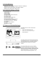
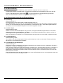
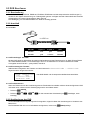
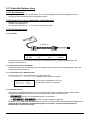
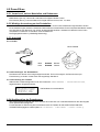
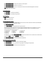
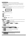
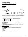
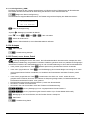
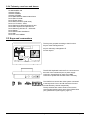
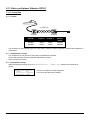
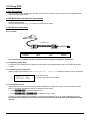
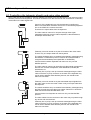
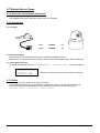
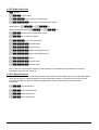
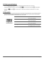
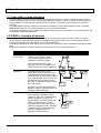
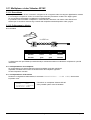
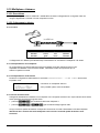
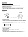
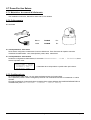
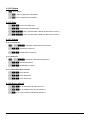
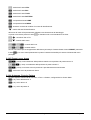
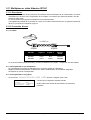
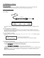
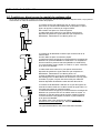
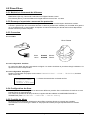
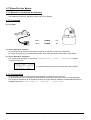
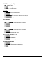
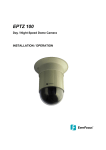
2.3 Tasten un d Steckverbindungen
Die Tasten sind ihrer Funktion entsprechend
angeordnet:
F+V
T
V
•
Tasten für die Videosteuerung V
•
Tasten für die Telemetriesteuerung T
•
Funktionstasten F
Die Tastatur besitzt auf der Rückseite der Mechanik
drei Steckerbuchsen RJ11, eine Versorgungsbuchse,
einen Dip-Schalter für die Konfiguration und eine
Buchse DB9 für die Vornahme von FirmwareUpdates.
Die Leitung VIDEO steuert die mit der Tastatur
verbundene Videoanlage. Die Leitungen A und B
steuern den ersten und zweiten Telemetriekanal. Der
Dip-Schalter erlaubt das Anlegen oder Entfernen des
Abschlußwiderstandes von 120 Ohm für jede der
beiden Leitungen RS48 (siehe § RS485 , S.10).
Seite 8
MNECKSKBJ_0350
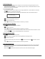
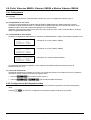
2.4 Zweitfunk tionstasten
, , ) gestatten die Aktivierung von Zweitfunktionen, wenn sie gleichzeitig mit
anderen Tasten gedrückt werden. Beispielsweise bedeutet , daß zunächst die Taste , dann die
Taste gedrückt wird, während weiterhin betätigt ist. Die beiden Tasten können in jeder beliebigen
Einige Tasten (
Reihenfolge losgelassen werden.
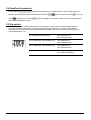
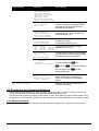
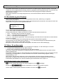
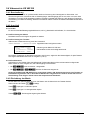
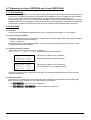
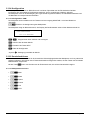
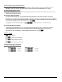
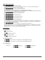
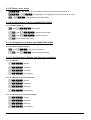
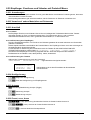
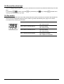
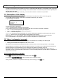
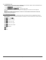
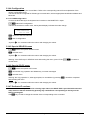
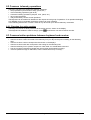
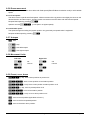
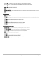
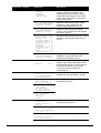
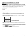
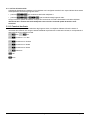
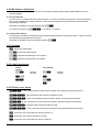
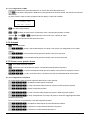
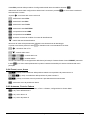
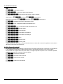
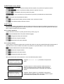
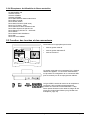
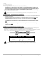
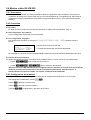
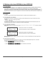
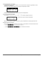
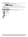
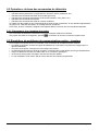
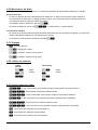
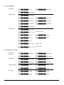
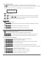
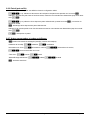
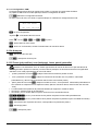
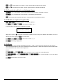
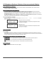
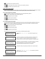
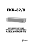
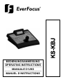
2.5 Dip switc h
Auf der Rückseite der Tastatur befindet sich ein Dip-Schalter, mit dem sich der Abschlußwiderstand der
Leitungen RS485 ein-/ausschalten und die Programmierung der Tastatur am PC sperren läßt. Weitere
Informationen zum Einschalten der Leitungsabschlußwiderstände entnehmen Sie bitte § Videoleitung und
Telemetrieleitungen, S.10.
DIP4: Widerstand Videoleitung
ON: Widerstand ein
OFF: Widerstand aus
DIP3: Widerstand Telemetrieleitung B
ON: Widerstand ein
OFF: Widerstand aus
DIP2: Widerstand Telemetrieleitung A
ON: Widerstand ein
OFF: Widerstand aus
DIP1: Firmware-Update von PC aus
ON: Update möglich
OFF: Update unzulässig
Seite 9
MNECKSKBJ_0350
3 Verbindun gsleitungen und Anschlüsse
3.1 Videoleitu ng und Telemetrieleitungen
Mit der Tastatur KS KBJ läßt sich eine große Bandbreite an Produkten zur Videosteuerung (Videomatrix
und Video-Multiplexer) und zur Telemetriesteuerung (Empfänger oder Domes) bedienen. Auf
Tastaturebene muß deshalb die Anlagengestaltung vorgenommen werden, damit die verbundenen
Einrichtungen fehlerfrei miteinander kommunizieren.
Unter “Videoleitung” versteht man den Kommunikationskanal, der für die Steuerung der Videoeinrichtung
bestimmt ist; “Telemetrieleitungen” sind die beiden Kanäle, die für die Steuerung der Fernübertragung
(Telemetriesteuerung) zur Verfügung stehen.
Es empfiehlt sich, erst nur die Einrichtung der “Videoleitung” vorzunehmen und in einem zweiten Schritt die
"Telemetrieleitungen" zu konfigurieren.
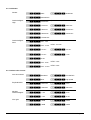
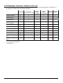
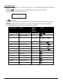
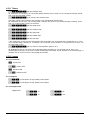
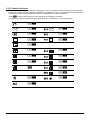
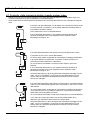
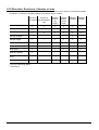
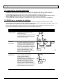
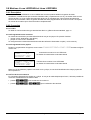
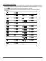
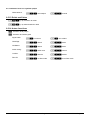
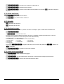
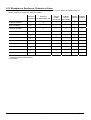
3.2 RS485 un d Anlagentypen
Die Kommunikationskanäle RS485 sind 2-adrige Leitungen, deren Länge zwischen zwei Enden 1.200 m beträgt.
Der Abschluß der Leitungen RS485 verhindert die Reflektierung des Signals entlang des Kabels und muß in jede
Einrichtung eingefügt werden, die am Ende der Verbindung anliegt.
Da sich die Anlagenarten unterscheiden, divergiert auch die Art des Leitungsabschlusses.
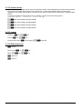
In den nachstehenden Darstellungen werden die abzuschließenden Einrichtungen mit dem Symbol bezeichnet.
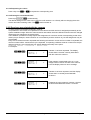
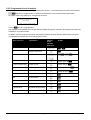
Konfiguration
Beschreibung
Beispiel
Stern /
Einzelleitungen
Für jede Verbindung zwischen zwei
Einrichtungen ist eine eigene
Kommunikationsleitung mit maximal
1.200 m Länge vorgesehen.
Alle Einrichtungen müssen mit einem
Abschluß versehen werden, weil jedes
Gerät an ein Leitungsende
angeschlossen ist.
Backbone
Es wird eine Einzelleitung benutzt, die
Sender können dort beliebig positioniert
werden. Die beiden Leitungsenden (im
Beispiel die Tastatur K und der Empfänger
R3) sind mit Abschluß versehen; die
anderen Einrichtungen (R1 und R2) nicht.
Die Höchstlänge der Leitung beträgt
1.200m.
Gemäß den Spezifikationen des
Standards RS485 können mindestens
32 Einrichtungen an derselben Leitung
angeschlossen werden.
Leitung mit Stubs Von der Leitung RS485 kann parallel
eine gewisse Anzahl von "Stubs" für
den Anschluß weiterer Einrichtungen
abgezweigt werden. “Stubs” müssen,
weil sie keine Leistungsenden
darstellen, nicht abgeschlossen
werden. Sie müssen sehr viel kürzer
sein (in der Größenordnung von zwei
Metern). Gemäß den Spezifikationen
des Standards RS485 können
mindestens 32 Einrichtungen an
derselben Leitung angeschlossen
werden.
Seite 10
MNECKSKBJ_0350
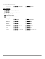
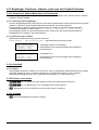
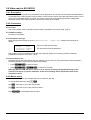
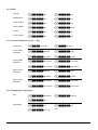
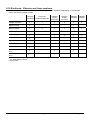
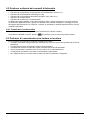
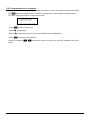
Konfiguration
Beschreibung
Beispiel
Einrichtungen
hintereinander
geschaltet
Die Einrichtungen werden paarweise
mit Einzelleitungen angeschlossen, die
an den Enden mit Abschluß versehen
werden müssen. Diese Art der
Konfiguration ist nur mit Einrichtungen
möglich, die jeweils einen getrennten
Kanal am Eingang/Empfangen und am
Ausgang/Senden haben (KS DTRX3).
Das aufgenommene Signal wird
"gesäubert" zur nächsten Einrichtung
geleitet. Wenn eine Einrichtung ausfällt,
wird gleichzeitig die Verbindung zu den
darauffolgenden Einrichtungen gekappt.
Die maximale Gesamtlänge entspricht
der Anzahl der Leitungen multipliziert
mit den 1.200 m jeder Teilstrecke.
Mischkonfiguration
Es lassen sich gemischte
Konfigurationen schaffen, bei denen
jedoch immer die vorstehend
beschriebenen Grenzen zu
berücksichtigen sind:
•
•
•
Jede Leitung kann höchstens 1.200
m lang sein
Jede Leitung muß an den Enden
abgeschlossen werden
Die Stubs müssen sehr kurz sein
(max. 2 m)
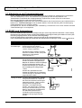
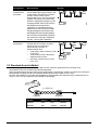
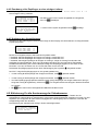
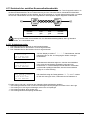
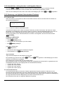
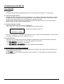
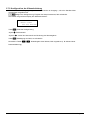
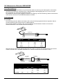
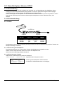
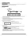
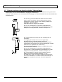
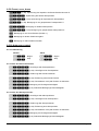
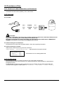
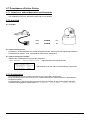
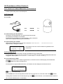
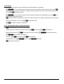
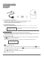
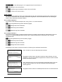
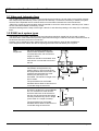
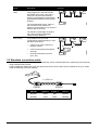
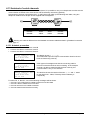
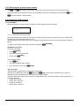
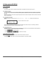
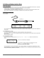
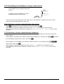
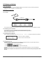
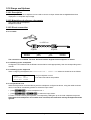
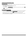
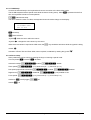
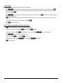
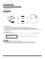
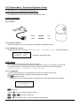
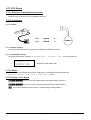
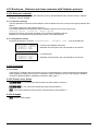
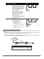
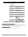
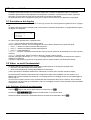
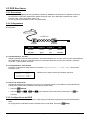
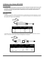
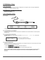
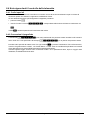
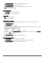
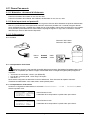
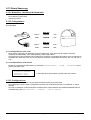
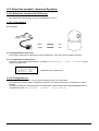
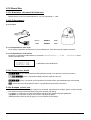
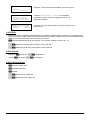
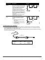
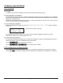
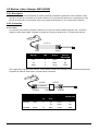
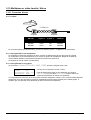
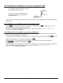
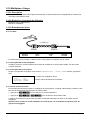
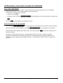
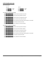
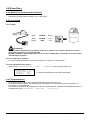
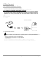
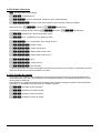
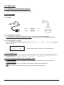
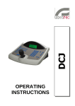
3.3 Standard-A nschlußkabel
Die Verbindung zwischen der Tastatur KS KBJ und den einzelnen gesteuerten Einrichtungen wird
ausschließlich über den seriellen Kanal RS485 hergestellt.
Wenn die gesteuerte Einrichtung diesen Kanal nicht besitzt, muß zwischen Tastatur und dieser Einrichtung ein
Signalwandler eingefügt werden (zum Beispiel RS485-RS232 oder RS485-Current Loop).
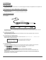
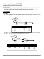
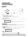
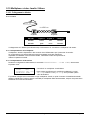
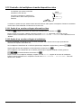
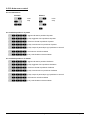
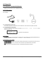
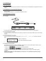
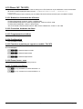
Ein Paar Telefonkabel und ein Paar Abzweigkästen RJjack gestatten die Überbrückung von Distanzen bis zu
1200 m, wenn man den folgenden Anschlußplan zugrundelegt:
L=1200 m
RJjack1
RJjack2
KS KBJ
RJjack 1
RJjack 2
Einrichtung
RS485A
weiß
blau
RS485A
RS485B
gelb
schwarz
RS485B
Seite 11
MNECKSKBJ_0350
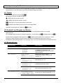
3.4 Eine Tast atur je Leitung
Der Anschluß wird mit dem Standardanschlußkabel vorgenommen, das im vorausgehenden Abschnitt
beschrieben wird.
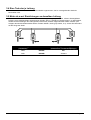
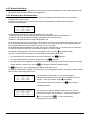
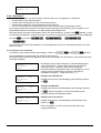
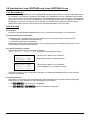
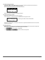
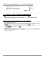
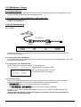
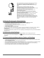
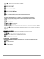
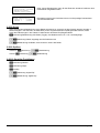
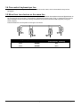
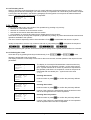
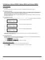
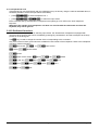
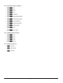
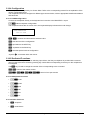
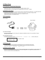
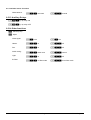
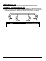
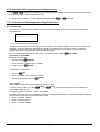
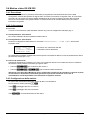
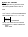
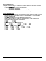
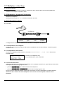
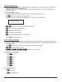
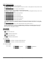
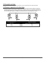
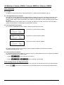
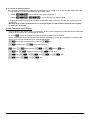
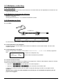
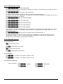
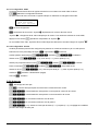
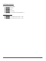
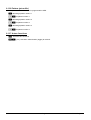
3.5 Mehr als z wei Einrichtungen an derselben Leitung
Sind mehrere Tastaturen an ein- und dieselbe Verbindungsleitung angeschlossen, müssen Abzweigkästen
RJjack je nach Gegebenheiten angeschlossen werden. Wie in § RS485 und Anlagentypen S.10 beschrieben,
werden zwei Einrichtungen als Leitungsenden bezeichnet, die dann abgeschlossen werden müssen (zum
Anlegen des Abschlußwiderstandes bei der Tastatur KS KBJ, siehe § Dip switch, S.9). Achten Sie besonders
auf die Länge der Stubs.
Sendeeinrichtungen
(Tastaturen)
Empfangseinrichtungen
(Videomatrix, Telemetrieempfänger)
Weiß
RS485A
Blau
Gelb
RS485B
Schwarz
Seite 12
MNECKSKBJ_0350
4 Konfiguri erung der Tastatur
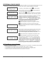
Die Programmierung erfolgt auf dem Anzeigenfeld der Tastatur. Im Folgenden werden die Programmierschritte
und die einzelnen, auf dem Display erscheinenden Menüeinträge beschrieben.
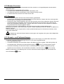
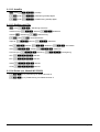
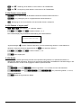
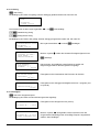
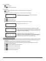
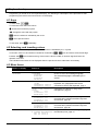
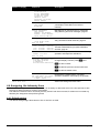
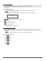
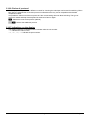
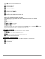
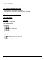
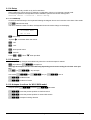
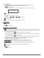
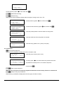
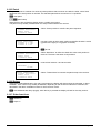
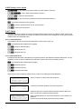
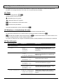
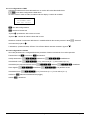
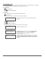
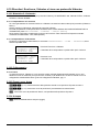
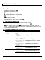
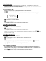
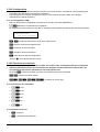
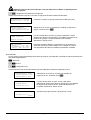
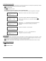
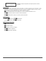
4.1 Tasten
Aufruf des Konfigurationsmodus:
Bewegen des Cursors innerhalb der Menüs:
Auswahl der Zeile mit dem Joystick
Änderung des Wertes mit dem Joystick
Aufruf des vom Cursor bezeichneten Untermenüs
Verlassen eines Menüs und Wechsel zum vorherigen Menü
Verlassen der Konfigurierung: Mehrmals drücken.
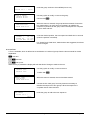
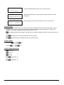
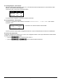
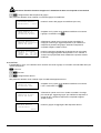
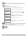
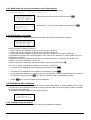
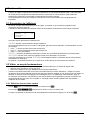
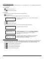
4.2 Auswahl und Eingabe von Werten
Wenn ein Menü mehrere Auswahlmöglichkeiten eröffnet, wird die gewählte Option vom Symbol
gekennzeichnet
Ist die Eingabe eines numerischen Wertes vorgesehen, so muß dieser mit
wird die zuletzt eingegebene Ziffer gelöscht, mit
bestätigt werden. Mit
verläßt man das Menü ohne zu speichern. Ist der
numerische Wert unzulässig, weist ein akustisches Signal das Bedienpersonal auf den Fehler hin.
Die einzelnen Menüoptionen werden nicht angezeigt, wenn die vorher getroffene Wahl sie überflüssig macht.
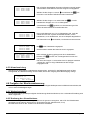
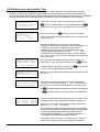
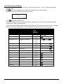
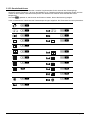
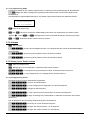
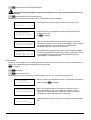
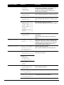
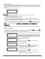
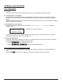
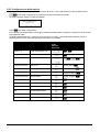
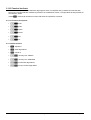
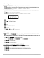
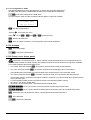
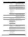
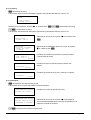
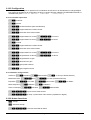
4.3 Menüopti onen
Displayanzeige
Untermenü
Beschreibung
Auswahl der Sprache, in der die Menüs
und Meldungen erscheinen. Die
ausgewählte Sprache wird vom Symbol *
gekennzeichnet
Definition der mit der Tastatur
verbundenen Geräte; siehe § An die
Tastatur S.7
Parameter der Videoleitung; siehe §
Videosteuerung S. 23.
Parameter der Telemetrieleitung A; siehe
§ Telemetriesteuerung, S.55
Parameter der Telemetrieleitung B; siehe
siehe § Telemetriesteuerung, S.55
Seite 13
Zuordnung der Empfängerleitung; siehe §
Zuordnung der Telemetrieleitungen, S. 15
MNECKSKBJ_0350
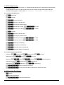
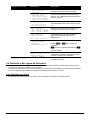
Displayanzeige
Untermenü
Beschreibung
Freigabe bei Ansteuerung von
Videokamera, Monitor, Funktionen und
Multiplexer. Mit der Aktivierung können die
Tastaturfunktionen auf sehr praktische Art
und Weise reduziert werden, ohne weitere
SystemPasswörter eingeben zu müssen
Aktivierung bei Ansteuerung einzelner
Kameras; siehe § Aktivierung für die
Ansteuerung der Videokameras, S. 16
Aktivierung bei Ansteuerung einzelner
Monitore; siehe § Freigabe der
Monitoransteuerung, S.18
Aktivierung beim Aufruf von Funktionen;
siehe § Freigabe der Funktionsanwahl,
S.19
Aktivierung bei Ansteuerung einzelner
Multiplexer; siehe § Freigabe der
Multiplexeransteuerung, S.19.
Nummer für die Identifikation der Tastatur
innerhalb des Systems. Jede Tastatur der
Anlage erhält eine andere Kennnummer:
Die Vergabe derselben Nummer an
mehrere Tastaturen kann
Kommunikationsprobleme verursachen
Kalibrierung und Test des Joystickes;
siehe § Kalibrierung und , S.20
Aktivierung des Warnmelders
Definition der TastaturPasswörter; siehe §
Passwor, S.21
Maskierte Eingabe des Passwortes
Maskierte Bestätigung des Passwortes
Seite 14
MNECKSKBJ_0350
Displayanzeige
Untermenü
Beschreibung
Wurde die Tastatur eine Minute lang nicht
bedient, versetzt die Energiesparfunktion
die Tastatur nach einer Minute in den
Niedrigverbrauchsmodus
Verwaltung der Hinweis- und
Fehlremeldungen; siehe § Hinweis- und
Fehlermeldungen, S.21
Autotest der seriellen Kanäle; siehe §
Autotest der seriellen
Kommunikationskanäle, S.22
Funktionstest des Joysticks; siehe §
Kalibrierung und , S.20
Test des internen Speichers, zweckmäßig
bei Fehlfunktionen oder Inanspruchnahme
des telefonischen Kundendienstes.
Verstellen des Displaykontrastes: zur
und
Kontrastveränderung
drücken, setzt den Kontrast auf
den vorherigen Wert, auf die
Werkseinstellungen.
Zurücksetzen der Werte auf die
Werkseinstellungen. Das Reset muß
vorher vom Bedienpersonal bestätigt
werden
Speichern der neuen Einstellungen und
Verlassen der Menüs
4.4 Zuordnun g der Telemetrieleitungen
Weil es zwei Telemetrieleitungen A und B gibt, muß festgelegt werden, auf welche Leitung (und somit auf
welches Protokoll) bei Ansteuerung eines Empfängers Bezug genommen wird.
Die Unterscheidung zwischen Leitung A und B macht nur Sinn, wenn beide Leitungen genutzt werden. Wird
mindestens eine von ihnen nicht genutzt, kann die Zuweisung von Telemetrieleitungen vernachlässigt werden.
4.4.1 Werkseinst ellung
Die Werkseinstellung (Default) weist der Leitung A sämtliche Empfänger zu; Leitung B wird nicht genutzt.
Seite 15
MNECKSKBJ_0350
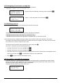
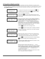
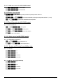
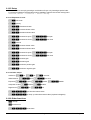
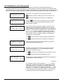
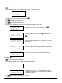
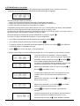
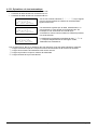
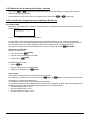
4.4.2 Zuordnung aller Empfänger zu einer einzigen Leitung
Alle Empfänger lassen sich im Untermenü
einer einzigen Leitung zuweisen:
Das Menü wird mit dem Joystick ausgewählt und aufgerufen,
dann mit
bestätigen.
wird mit dem Joystick angewählt und mit
bestätigt.
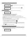
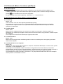
4.4.3 Änderung d es Verzeichnisses
Das Menü für die Änderung des Verzeichnisses zeigt auf dem Display die verschiedenen zu konfigurierenden
Empfängergruppen:
Rechts im Anzeigefeld müssen drei besondere Symbole stehen:
bedeutet, daß alle Empfänger der Gruppe mit Leitung A verbunden sind
bedeutet, daß alle Empfänger der Gruppe mit Leitung B verbunden sind
bedeutet, daß einige Empfänger der Gruppe mit Leitung A, einige mit Leitung B verbunden sind.
Verfügbar sind 999 Empfänger, auch wenn die Anlage vermutlich aus einer geringeren Zahl besteht.
Die Bildschirmdarstellung aus unserem Beispiel schlägt drei Empfängergruppen vor: die erste mit den
Nummern 1 bis 100; die zweite von 101 bis 200; die dritte von 201 bis 300.
Die anderen Empfängergruppen können durch die Bewegung des Joysticks
ausgewählt werden.
Der Pfeil zeigt die Empfängergruppe an, die gerade gebildet wird:
gedrückt werden.
um der Leitung A alle Empfänger der Gruppe zuzuweisen, muß gedrückt werden.
muß die Empfängergruppe präziser definiert werden (einige Empfänger der Gruppe werden der Leitung A,
einige der Leitung B zugewiesen), drückt man , um die gekennzeichnete Gruppe in kleinere Einheiten
zu zerlegen.
Mit kehrt man zu den vorhergehenden Bildschirminhalten zurück.
• um der Leitung B alle Empfänger der Gruppe zuzuweisen, muß
•
•
•
4.5 Aktivierun g für die Ansteuerung der Videokameras
Die Freigabe für die Ansteuerung der Videokameras erlaubt es, die Benutzung der Tastatur auf die
freigegebenen Videoeingänge zu beschränken, ohne weitere SystemPasswörter eingeben zu müssen. Es wird
empfohlen, die Gruppe der für jede Tastatur freigegebenen Videoeingänge erst zu definieren, nachdem die
Anlagenkonfiguration klar feststeht.
Die Aktivierung der Videokameras erfolgt in einem zweistufigen Menü:
Seite 16
MNECKSKBJ_0350
4.5.1 Werkseinst ellung
Die Werkseinstellung (Default) gestattet die Steuerung sämtlicher Videokameras, eine möglicherweise vorher
bestehende abweichende Einstellung wird aufgehoben.
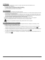
4.5.2 Änderung d es Verzeichnisses
Die Änderung des Verzeichnisses erlaubt die genauere Festlegung der Kameras, die von der Tastatur
angesprochen werden können.
Das Menü zur Änderung des Verzeichnisses zeigt im Anzeigenfeld die verschiedenen Gruppen zu
konfigurierender Kameras:
Drei besondere Symbole rechts auf dem Display sind zu erkennen:
bedeutet, daß keine der zur entsprechenden Gruppe gehörenden Kameras freigegeben ist
bedeutet, daß einige Kameras der Gruppe freigegeben sind und andere nicht
bedeutet, daß alle Kameras der Gruppe freigegeben sind.
Bis zu 9999 Videokameras sind verfügbar: In der Regel wird man eine sehr viel kleinere Gruppe nutzen, aber
die Auswahlbreite des Intervalls kommt dann zum Tragen, wenn die Videoanlage mit groß dimensionierten
Einrichtungen gesteuert wird, die mit dem Konzept der "Zone" arbeiten.
Der beispielhaft dargestellt Bildschirm schlägt drei Gruppen Videokameras vor: die erste reicht von Nummer 1
bis 1000; die zweite von Nummer 1001 bis 2000; die dritte von 2001 bis 3000.
ausgewählt werden.
Der Pfeil kennzeichnet die Gruppe von Videokameras, die gerade gebildet wird:
• Um das Ansprechen aller Kameras der Gruppe zu aktivieren, wird gedrückt.
• Um alle Videokameras der Gruppe zu deaktivieren, wird gedrückt.
• Muß die Gruppe der freigegebenen Videokameras genauer festgelegt werden (einige Kameras der Gruppe
werden aktiviert, andere nicht), wird mit die Gruppe in kleinere Einheiten zerlegt.
Mit kehrt man zu den vorangegangenen Bildschirminhalten zurück.
Die anderen Kameragruppen können durch die Bewegung des Joysticks
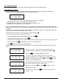
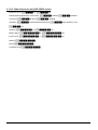
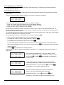
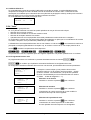
Im folgenden Beispiel wird erläutert, wie die Kameras 1 bis 7 freigegeben werden, der Zugang zu allen anderen
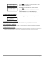
Kameras aber gleichzeitig gesperrt wird:
Alle Videokameras der Gruppe 1-1000 sind freigegeben,
während die Kameras 1001 bis 3000 nicht freigegeben sind. Die
ausgewählt,
anschließend werden durch Drücken von alle Kameras
Gruppe 1-1000 wird mit dem Joystick
vollständig gesperrt.
Die Ikonen rechts auf dem Display weisen darauf hin, daß nun
keine der Kameras in den Gruppen von 1 bis 3000 angesprochen
werden kann. Wählen Sie die Gruppe 1-1000 mit dem Joystick
aus und drücken Sie , um mit einem feineren
Definitionsniveau fortzufahren.
Seite 17
MNECKSKBJ_0350
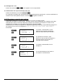
Die im Display dargestellten Gruppen umfassen nunmehr jeweils
100 Kameras. Keine Kamera aus den Gruppen ist freigegeben.
Wählen Sie die Gruppe 1-100 mit
und drücken Sie um
mit einem noch feineren Definitionsniveau fortzufahren.
Wählen Sie die Gruppe 1-10 und drücken Sie
, um alle
Kameras der Gruppe von 1 bis 10 freizugeben.
Anschließend wird
gedrückt, um die Aktivierung auf die
Ebene einzelner Kameras herunterzubrechen.
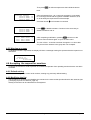
Da nun alle Kameras von 1 bis 10 freigegeben sind, muß das
Verzeichnis mit dem Joystick durchlaufen werden, um die
Kameras 8,9,10 zu deaktivieren, wie es im Beispiel dargestellt ist.
Das Verzeichnis mit
Mit
durchlaufen, bis die Kamera 8 erreicht ist.
wird Videokamera 8 gesperrt
Gleichermaßen werden die Kameras 9 und 10 gesperrt.
Nach erfolgter Änderung gelangt man durch wiederholtes
Drücken von
zurück zum vorherigen Menü bis hin zum
Hauptmenü.
Die Ikone der Gruppe 1-10 hat weist durch ihr jetziges Aussehen
darauf hin, daß nur einige Videokameras der Gruppe
freigegeben sind.
4.5.3 Hinweisme ldung
Wird eine nicht freigegebene Videokamera angesprochen, erscheint für das Bedienpersonal auf dem
Anzeigenfeld eine Hinweismeldung mit dem Inhalt, daß für den Vorgang keine Berechtigung vorliegt.
4.6 Freigabe der Monitoransteuerung
Mit der Freigabe der Monitore wird vermieden, daß unbefugtes Bedienpersonal mit Bildschirmen arbeitet, die
nicht in seiner Zuständigkeit liegen.
4.6.1 Werkseinst ellung
Die Werkseinstellung (Default) ermöglicht die Steuerung sämtlicher Monitore, eine vorhandene Einstellung wird
dabei aufgehoben.
4.6.2 Änderung d es Verzeichnisses
Für die Aktivierung und Deaktivierung der Monitore ist genauso vorzugehen, wie es für die Videokameras
geschildert wurde (siehe § Aktivierung für die Ansteuerung der Videokameras, S.16).
Normalerweise sind von der Tastatur aus 99 Monitore anwählbar.
Seite 18
MNECKSKBJ_0350
4.7 Freigabe der Multiplexeransteuerung
Mit der Freigabe der Multiplexer wird vermieden, daß unbefugtes Bedienpersonal mit solchen Multiplexern
arbeiten kann, die nicht in seiner Zuständigkeit liegen.
4.7.1 Werkseinst ellungen
Die Werkseinstellung (Default) ermöglicht die Steuerung sämtlicher Multiplexer, eine vorhandene Einstellung
wird dabei aufgehoben.
4.7.2 Änderung d es Verzeichnisses
Für die Aktivierung und Deaktivierung der Multiplexer ist genauso vorzugehen, wie es für die Videokameras
geschildert wurde (siehe § Aktivierung für die Ansteuerung der Videokameras, S.16).
Normalerweise sind von der Tastatur aus 39 Multiplexer anwählbar.
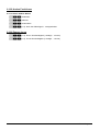
4.8 Freigabe der Funktionsanwahl
Jeder Bediener kann eine Berechtigung zu beestimmten Operationen mit der Tastatur besitzen oder nicht.
Diese Vorgänge sind in folgende Funktionsgruppen unterteilt:
•
•
•
•
•
•
•
•
•
•
•
:
Freigabe der Kameraanwahl mit den Tasten
und ; weil diese Tasten die
zyklische Umschaltsequenz unterbrechen können, ist es möglicherweise erforderlich, sie zu sperren, wenn
diese Eventualität ausgeschlossen werden soll.
: Freigabe des Monitorwechsels; wenn ein Bediener nur einen einzigen Monitor zur
Verfügung hat, kann dieser blockiert, also nicht mehr gewechselt werden
: Freigabe zur Konfiguration der Videoeinrichtung (Umschalter oder Matrix); auch bei
erteilter Freigabe kann eine Passwortabfrage vorgesehen werden
: Freigabe zur Konfiguration der Telemetrieempfänger oder Domes; auch bei erteilter
Freigabe kann eine Passwortabfrage vorgesehen werden
: Freigabe zum Reset von Alarmen der Videoeinrichtung; auch bei erteilter Freigabe kann
eine Passwortabfrage vorgesehen sein
: Freigabe zur Benutzung des Joystick
: Freigabe zur Funktionssteuerung der Optiken in den Telemetrieempfängern
: Freigabe zur Bewegungsänderung des Schwenkkopfes / Domekamera bei Erteilung von
Steuerbefehlen des Typs Autopan und Scan.
: Freigabe zur Änderung der Empfängernummer, die einer Kamera zugeordnet ist
: Freigabe der Relaissteuerung
: Freigabe zur Steuerung der Pumpe und des Scheibenwischers
Seite 19
MNECKSKBJ_0350
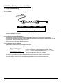
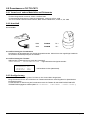
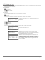
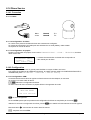
4.9 Kalibrieru ng und Joystick- Test
Bei der Kalibrierung wird das Joystick so eingerichtet, daß er korrekt funktioniert. In der Regel wird sie nur bei der
Herstellung vorgenommen, der Bediener sollte eigentlich nicht in die Verlegen-heit kommen, eine Neukalibrierung
durchzuführen. Verhält sich das Joystick allerdings fehlerhaft (z.B. wenn die Bewegung in eine Richtung in den Modalitäten
Pan oder Tilt bestehen bleibt, obwohl das Joystick in Ruhestellung ist) kann die Kalibrierung zweckmäßig sein.
Erste Phase: mit dem Joystick in Ruhestellung (losgelassen)
drücken. Dadurch wird der Ruhepunkt bestimmt. Mit
wechselt man zum Test, ohne die Kalibrierung zu durchlaufen.
Nach dem Drücken von
muß das Joystick so bewegt
werden, daß er den Maximalausschlag nach oben, unten, rechts
und links erreicht.
Während der Bewegung erscheinen auf dem Display
eingelesene Werte. Es sind Parameter, die für den Bediener nur
im Falle von Fehlfunktionen Bedeutung haben, weil sie
Hilfestellung beim telefonischen Kundendienst bieten. Das
Joystick muß bewegt werden, bis die von , , und
angegebenen Werte (Wertebezeichnungen für die Endpunkte
links, rechts, unten und oben) sich bei Bewegung des Knüppels
nicht mehr ändern.
Die in der Mitte des Displays stehenden Werte ändern sich
wird der
nächste Schritt der Konfiguration eingeleitet. Mit wechselt man
kontinuierlich, wenn das Joystick bewegt wird. Mit
zum Test, ohne die Kalibrierung abzuschließen.
Während des Normalbetriebes aktiviert die Drehung des Joystick
den Zoom.
Das Joystick wird mehrmals bis zu den beiden Endpunkten
gedreht, bis sich die Werteangaben und (Endpunkte für
den positiven und negativen Uhrzeigersinn) nicht mehr ändern.
wird die Konfiguration abgeschlossen und der Test eingeleitet,
mit wechselt man zum Test, ohne den Zoom neu zu kalibrieren.
Mit
Test des Joysticks: Nach der Kalibrierung kann mit seiner Hilfe
überprüft werden, ob die Kalibrierung erfolgreich verlaufen ist.
Wenn das Joystick sich in Ruhestellung befindet, müssen die
Werte von , und 0 betragen.
Das Joystick ist zu bewegen, bis der Endpunkt in den vier Richtungen
erreicht ist. Er ist außerdem im postitiven und negativen Uhrzeigersinn
zu drehen, bis die Endpunkte erreicht sind. Wenn nach diesen
Vorgängen die drei Parameter und die drei Parameter
anzeigen, ist die Kalibrierung erfolgreich verlaufen.
Andernfalls muß das Joystick neu kalibriert werden, weil seine
fehlerhafte Konfiguration die Funktionsfähigkeit einschränkt.
Seite 20
MNECKSKBJ_0350
4.10 Buzzer (S ummer)
Die Tastatur ist mit einem Buzzer ausgestattet, der beim Auftreten von Unregelmäßigkeiten als akustischer
Warnmelder dient.
Der Summer kann so eingestellt werden, daß er:
• vor Alarmen der Videoeinrichtung (Umschalter oder Matrix) warnt
• auf Unterbrechungen der Verbindungen mit der Videoeinrichtung hinweist
• ein kleines Klick beim Drücken einer Taste ertönen läßt.
4.11 Passwort
Die Sicherheit der Tastatur wird durch drei Passwortstufen gewährleistet:
• Passwort beim Einschalten: Diese Passwortabfrage bei Einschalten der Tastatur soll deren unsachgemäße
Benutzung durch unbefugtes Personal verhindern
• Passwort für Setup: Passwortabfrage, die immer dann erscheint, wenn eine Konfiguration ansteht. Bei einem
Anschluß bestimmter Videogeräte (KS VM 164) wird das Passwort nicht verlangt, weil es direkt auf der
Ebene des Videogerätes abgefragt wird: In diesem Fall muß ein solches nach den Angaben im Handbuch
der gesteuerten Einrichtung eingegeben werden
Passwort für Alarmreset: Passwortabfrage, wenn das Reset eines Alarmzustand beabsichtigt ist.
Die Passwörter werden auf der Ebene jeder einzelnen Tastatur festgelegt und können deshalb von Bediener zu
Bediener variieren.
Passwortanfragen können ausgeschlossen werden (Defaulteinstellungen bei Verlassen des Werkes), indem
man sie auf 00000 setzt.
Zur Beachtung: Wenn das Setup-Passwort verloren geht oder vergessen wird, gibt es keine Möglichkeit,
es wieder aufzufinden.
4.12 Hinweis- und Fehlermeldungen
Die Tastatur benachrichtigt den Bediener durch Meldungen auf dem Display vom fehlerhaften Ablauf eines
veranlaßten Vorganges. Diese Meldungen können auf vier Arten eingestellt werden:
• Nicht angezeigte Meldungen
• Automatische Meldung ohne warnenden Piepton: Die Meldung wird für ungefähr 3 Sekunden gezeigt und
kann sie vorzeitig entfernt werden.
• Automatische Meldung mit warnendem Piepton: Die Meldung wird für ungefähr 3 Sekunden gezeigt,
begleitet von einem Warnton. Sie verschwindet automatisch, durch Drücken von auch vorzeitig.
Meldung mit Quittierung: Die Meldung wird von einem warnenden Piepton begleitet und verschwindet erst,
wenn der Bediener drückt.
verschwindet dann automatisch ohne akustisches Signal; mit
Seite 21
MNECKSKBJ_0350
4.13 Autotest d er seriellen Kommunikationskanäle
Bei Störungen oder zur Überprüfung der Tastatur kann anhand eines einfachen Tests festgestellt werden, ob
die Kommunikationskanäle, die zur Videoeinrichtung und zur Telemetrie führen, einwandfrei funktionieren.
Trennen Sie die Verbindung zu den Geräten, die an die Leitungen V, A und B angeschlossen sind, und stellen
Sie mit zwei Telefonkabeln und den zwei mitgelieferten Abzweigdosen RJjack folgendes Testkabel her:
Telefonkabel
RJjack 1
RJjack 2
Telefonkabel
RS485A
weiß
weiß
RS485A
RS485B
gelb
gelb
RS485B
Achtung: Dieses Kabel unterscheidet sich vom Standardverbindungskabel, das in § StandardAnschlußkabe, S.11 beschrieben wird.
4.13.1 Autotestpro zedur
• Das Kabel wird an die Buchsen A und B angeschlossen.
• Das Testkabel wird an die Buchsen A und V angeschlossen
• Das Testkabel wird an die Buchsen B und V angeschlossen.
Auf dem Display erscheint . Das bedeutet, daß die
Übertragungen am Ein- und Ausgang der beiden Leitungen
funktionieren.
Anderslautende Hinweise zeigen an, daß das Anschlußkabel
nicht richtig ist oder daß die getesteten Leitungen nicht
funktionieren. In unserem Beispiel sendet Kanal A einwandfrei
und Kanal B empfängt einwandfrei, aber die Kommunikation
erfolgt nur in einer Richtung.
Die dritte Zeile zeigt die Testergebnisse: , und stehen
für die drei Leitungen Video, Telemetrie B und Telemetrie A.
Für jede Leitung A,B und V wird einer der folgenden Diagnosehinweise gegeben:
: Die Leitung funktioniert nicht und ist zum Übertragen oder Empfangen von Daten nicht in der Lage
: Die Leitung ist in der Lage zu übertragen, aber nicht zu Empfangen
: Die Leitung empängt, aber sendet nicht
: Die Leitung sendet und empfängt einwandfrei.
Seite 22
MNECKSKBJ_0350
4.14 Protokoll Macro: Sonderfunktionen
4.14.1 Beschreibu ng
Das Protokoll Macro für die Videoleitung kann spezifisch konfiguriert und so an besondere
Anlageneigenschaften angepaßt werden. Nachdem das Protokoll Macro ausgewählt wurde, führen Sie den
Cursor auf die Zeile Protokoll und drücken
, um das Untermenü für die Konfigurierung aufzurufen.
Wenn eine Sonderfunktion aktiviert ist, folgt auf die Zeichenfolge ein .
4.14.2 Sonderfunk tionen für das Protokoll Macro
4.14.2.1 Polling
Werkseinstellung: JA.
Die Verbindung mit einer Matrix sieht normalerweise das Polling vor.
Ist die Bedientastatur mit einem PC oder einem OEM-Gerät verbunden, kann das Polling vorläufig ausgesetzt
werden, um die Implementierung des Protokolls Macro zu vereinfachen und um keine Zeitvorgaben beachten
zu müssen, die in nicht dedizierten Systemen schwerlich eingehalten werden.
4.14.2.2 Mux Sanyo
Werkseinstellung: NEIN.
Stellen Sie JA ein, wenn der Multiplexer Sanyo an eine Leitung Aux der Matrix angeschlossen ist. Auf diese
Weise werden einige normalerweise von der Tastatur nicht gezeigte Spezialbildschirme aktiviert, welche die
vollständige Steuerung des Multiplexers gestatten.
Wenn der Multiplexer unmittelbar von einer Bedientastatur aus gesteuert wird, muß NEIN vorgegeben werden.
4.14.2.3 9999 Kamera s
Werkseinstellung: NEIN.
JA einstellen, wenn die Anlageneigenschaften (mehrere Matrizen werden von derselben Tastatur gesteuert)
den Gebrauch von 9999 Kameras gestatten.
4.14.2.4 Dekodierung der Empfänger
Werkseinstellung: JA.
Gewöhnlich ist einem Videoeingang ein Telemetrieempfänger mit derselben Nummer zugehordnet (Eingang 1 /
Empfänger 1, Eingang 2 / Empfänger 2 etc.)
Sollte es wegen bestimmter Anlageneigenschaften erforderlich sein, unterschiedliche Nummern vorzugeben, so
muß die Zuordnung zwischen Eingang und Empfänger berechnet werden. Diese Dekodierung kann von der
Bedientastatur (Normalzustand) oder der Matrix aus durchgeführt werden. Die letztere Option ist nicht in allen
Matrixversionen enthalten.
Wenn die Dekodierung von der Matrix aus aktiviert ist, kann die Empfängernummer nicht angewählt werden, die
in diesem Fall nicht auf dem Display erscheint.
Seite 23
MNECKSKBJ_0350
5 Videosteu erung
Die Tastatur besitzt hinten eine Steckerbuchse VIDEO für die Steuerung der Videoeinrichtungen. Sowohl die
Tastatur als auch die gesteuerte Einrichtung müssen in geeigneter Weise eingestellt werden, weil einerseits das
gewählte Kommunikationsprotokoll und andererseits die Übertragungsgeschwindigkeit (Baudrate)
übereinstimmen müssen.
Wenn diese Parameter nicht richtig konfiguriert sind, ist eine Kommunikation zwischen den Einrichtungen
unmöglich.
5.1 Beschreib ung des Displays
Wenn mit der Bedientastatur ein DVR Everfocus gesteuert wird, siehe § Steuerung von digitalen
Videorekordern auf Seite 25.
Die Tastatur KS KBJ hält auf ihrem Display alle für das Bedienpersonal erforderlichen Informationen bereit. Das
Display stellt sich typischerweise folgendermaßen dar:
Die vier Zeilen haben folgende Bedeutung:
: Die zuletzt vom Bediener angewählte Kamera.
Erscheint keine Nummer, sondern eine Ikone, so wurden Sonderfunktionen benutzt wie:
• Ikone : Nächste Kamera innerhalb der Sequenz
• Ikone : Vorhergehende Kamera innerhalb der Sequenz
• Ikone : Automatische Umschaltfrequenz
: Der Kamera zugeordneter Telemetrieempfänger; alle telemetrischen Operationen werden diesem
Empfänger zugeleitet
Aktiver Monitor, alle Videooperationen werden an diesen Monitor geleitet
Nachrichtenzeile mit den Meldungen (im Beispiel: ): Die Alarmmeldungen und die Bezeichnung der
gedrückten Tasten werden in dieser Zeile angezeigt.
Das Symbol kennzeichnet die Position des Joysticks und ändert sich mit dessen Bewegung.
5.2 Video: Gr undkonzepte
Die Tastatur KS KBJ gestattet 2 Arten von grundsätzlichen Vorgängen, um das Videosignal zu steuern:
• Auswahl einer Videokamera auf dem aktiven Monitor
• Beginn einer vorgegebenen Zyklussequenz auf dem aktiven Monitor
Alle von der Tastatur aus aufgerufenen Vorgänge beziehen sich auf den aktiven Monitor, der stets auf dem
Display angezeigt wird.
Die Anwahl der Kamera hängt von der Konfiguration der freigegebenen Kameras ab. Wenn eine Kamera für die
Ansteuerung nicht freigegeben ist, wird der Anwahlversuch von einer Fehlermeldung begleitet; siehe §
Hinweismeldung, S.18.
Man beachte, daß nicht alle Funktionen von den verschiedenen Videoeinrichtungen akzeptiert werden
(Umschalter und Matrix). Beim Aufruf einer für eine Videoeinrichtung nicht zugelassenen Funktion teilt eine
Fehlermeldung dem Bediener mit, daß die Ausführung des Steuerbefehls nicht möglich ist.
5.2.1 Direkte Anwa hl einer Videokamera
drücken, danach die Nummer der Kamera eingeben und mit bestätigen.
Beispiel: Mit wird die Videokamera 12 auf den aktiven Monitor geholt.
Soweit möglich ist die Eingabe automatisch beendet, ohne die Taste abzuwarten.
Seite 24
MNECKSKBJ_0350
5.2.2 Auswahl de r vorhergehenden / nachfolgenden Kamera
und ermöglichen die Auswahl der vorhergehenden und der nächsten Kammera
innerhalb der Umschaltsequenz, die auf der Ebene der Videoeinrichtung vorgegeben wurde.
Wenn die Umschaltsequenz läuft, wird sie durch die erste Betätigung der Tasten und angehalten.
Die Tasten
5.2.3 Steuerung von digitalen Videorekordern Everfocus
5.2.3.1 Modus DVR
Wenn die Tastatur so konfiguriert ist, daß sie einen DVR Everfocus steuert, erscheint beim Einschalten ein
personalisierter Bildschirm:
steht für die Nummer des aktiven DVR.
Im Modus DVR aktivieren die Tasten die zweiten Funktionen (in heller Farbe neben oder über den Tasten
dargestellt): Um die Bedeutung der einzelnen Tasten zur erfahren, siehe das Betriebshandbuch des DVR. Im
Modus DVR ist die vollständige Steuerung des DVR möglich, nicht jedoch die Telemetriesteuerung.
Um vom DVR-Modus in den Telemetrie-Modus zu wechseln und umgekehrt, drücken Sie bitte die Taste
[
DVR MODE].
Vorgänge im Modus DVR
Anwahl des aktiven DVR:
DEVICE
] drücken
Die Nummer des DVR eingeben (von 0 bis 16382)
]. bestätigen
Mit [
• Taste [
•
•
MODE
Aufruf eines Videokanals:
•
[
CH]
drücken
• Die Nummer des angeforderten Videokanals eingeben
• Falls erforderlich, mit [
MODE]
bestätigen.
Jog und shuttle
Jog und shuttle entsprechen dem Regler auf dem DVR.
Der Tipbetrieb (jog) wird mit den Tasten [
JOG<]
JOG>]
und [
gesteuert: Jeder Betätigung der Tasten
entspricht eine Raste des Jog-Reglers.
Durch Drehen des Joysticks läßt sich der Shuttle steuern.
Das Joystick dient nicht nur zur Bewegung innerhalb der Konfigurationsmenüs des DVR, er gestattet auch die
Schnellanwahl der ersten vier Eingänge (falls vom DVR-Modell unterstützt):
• Joystick nach links: Kanal 1
• Joystick nach rechts: Kanal 2
• Joystick nach oben: Kanal 3
• Joystick nach unten: Kanal 4.
5.2.3.2 Telemetriemo dus
Im Telemetriemodus läßt sich die an die Tastatur angebundene Telemetrie steuern. Es läßt sich nur die
Nummer des aktiven DVR ändern und einen Videoeingang aufrufen. Alle Zifferntasten werden für den Aufruf
der Ansichten benötigt (die im folgenden Abschnitt beschrieben sind) während des Joysticks für die Bewegung
der angeschlossenen Schwenk-Neige-Köpfe oder Dome-Kameras benutzt wird.
Der Telemetriemodus wird von folgendem Bildschirm angezeigt:
Seite 25
MNECKSKBJ_0350
5.2.4 “Ansichten ”
Die “Ansicht” gestattet es, mit einer einzigen Taste eine Serie von 4 Vorgängen zu veranlassen:
• Auswahl eines neuen aktiven Monitors
• Auswahl einer Videokamera auf dem neuen aktiven Monitor
• Auswahl des Empfängers, der der Videokamera zugeordnet ist
• Scan in eine Position des Schwenkkopfes, die zuvor auf dem Empfänger gespeichert wurde.
Die richtige Einstellung der Ansichten ermöglicht die Beschleunigung der Steuerung durch Vorgabe von 10
bedienerdefinierbaren Kombinationen von Kamera/Monitor/Empfänger/scan.
Kamera 12 (was
normalerweise Empfänger 12 entspricht), Monitor 3 und Scan 5 zugewiesen, so ersetzt die einfache Betätigung
der Taste die Sequenz
.
Der Gebrauch der Ansichten ist besonders nützlich bei Alarmsituationen: Sind der Taste
Durch Drücken der Taste hat der Bediener somit die Möglichkeit, rasch eine vorbestimmte Position auf einen
Monitor zu holen.
5.2.4.1 Definition der Ansichten
Zur Definition einer Ansicht werden gleichzeitig die Tasten von
bis gedrückt,
wenn der Bediener zur Konfiguration der Ansichten berechtigt ist.
Das Display zeigt die aktuelle Konfiguration der Ansicht für ungefähr eine Sekunde an, dann werden die neuen
Parameter abgefragt:
Das Display zeigt in diesem Beispiel an, daß bei Betätigung der
Taste 1 die Kamera 1 auf dem aktiven Monitor angesprochen
wird (das Symbol bedeutet, daß für den Vorgang kein
besonderer Monitor ausgewählt wurde), daß hingegen kein ScanVorgang für die Schwenk-Neige-Vorrichtung der Kamera
erforderlich ist (Symbol neben dem Wort ).
Einfügen der Videokamera.
Einfügen des Monitors.
Eingabe einer Nummer oder Bestätigung der bisherigen Kamera
mit
.
Eingabe einer Nummer oder Bestätigung des bisherigen Monitors
mit
. Wird 0 eingegeben, muß der aktive Monitor beim
Aufruf der Ansicht nicht geändert werden.
Einfügen der Scan-Position.
Eingabe einer Nummer oder Bestätigung der bisherigen ScanPosition mit
.
Wird 0 eingegeben, so ist bei Aufruf der Ansicht kein ScanVorgang erforderlich.
Seite 26
MNECKSKBJ_0350
5.2.4.2 Aufrufen der Ansichten
Mit den Tasten
bis werden die jeweiligen Ansichten aufgerufen.
5.2.4.3 Entfernung b enutzerdefinierter Ansichten
gedrückt.
Die Werkseinstellung der Ansichten gestattet das direkte Ansprechen der Kameras 1 bis 9, ohne Änderungen
des aktiven Monitors und ohne Scan-Vorgänge. Die Taste spricht Kamera 10 an.
Hierzu werden gleichzeitig die Tasten
5.2.5 Den Videok ameras zugeordnete Empfänger
Jeder Videokamera wird ein Telemetrieempfänger zugewiesen.
Dabei kann für jede Kamera ein einzelner Empfänger vorhanden sein, der bei der Anlageninstallation
unabänderlich zugeordnet wird. Wenn die Verknüpfung zwischen Videokamera und Empfänger festgelegt
wurde, darf diese Zuordnung nur noch bei Änderungen an der Anlage modifiziert werden.
Die Installationspraxis sieht im Normalfall vor, daß einem Videoeingang die entsprechende Empfängernummer
zugewiesen wird (Beispielsweise wird Videokamera 10 vom Empfänger Nummer 10 gesteuert), diese
Verknüpfungen sind jedoch flexibel handhabbar.
Jedesmal, wenn eine Videokamera angesprochen wurde und nach dieser Anwahl eine neue
Empfängernummer aufgerufen wird, so "erinnert" sich die Tastatur an diese Empfängernummer. Soll die
Möglichkeit zum Ansprechen einer von der zugewiesenen Nummer abweichenden Empfängernummer
ausgeschlossen werden, so empfiehlt es sich, im Konfigurationsmenü die Option /
/ zu deaktivieren.
Ein Beispiel soll dies verdeutlichen:
Angesprochen wurde Kamera 1. Auf dem
Display wird angezeigt, daß dieser Kamera
momentan Empfänger Nr. 1 zugeordnet ist.
Wenn der Bediener dazu berechtigt ist, kann er
der Videokamera eine andere
Empfängernummer zuweisen; andernfalls
erscheint eine Fehlermeldung.
Kamera 2 wird angesprochen, gezeigt wird der
momentan zugeordnete Empfänger 2.
Bei einem erneuten Aufruf der Kamera 1 wird
der zuletzt der Kamera 1 zugewiesene
Empfänger angezeigt.
Seite 27
MNECKSKBJ_0350
5.3 DVR Ever focus
5.3.1 Beschreibu ng
Die DVR Everfocus (EDSR400, EDSR100, EDSR900, EDSR1600 und die entsprechenden Ausführungen H)
werden für die digitale Aufzeichnung von Videosignalen genutzt. Verfügbar sind die Videoschleife der einzelnen
Videoeingänge und zwei Videoausgänge, Main und Call.
Die Übertragung von der Bedientastatur zum DVR ist einseitig gerichtet.
5.3.2 Anschluß
5.3.2.1 Kabel
L=1200 m
RJjack1
RJjack2
KS KBJ
RJjack 1
RJjack 2
DVR
RS485A
weiß
gelb
RS485A
RS485B
gelb
schwarz
RS485B
5.3.2.2 Einstellungen des DVR
Mit dem DVR-eigenen Steuerbrett die gewünschte Baudrate und die Einheitsnummer im Menü RS232/RS485
SETTING MENU einstellen. Zu berücksichtigen sind nur die Parameter für die Kommunikationen RS485.
Vorzugeben sind STOP BIT 1, parity NONE, data bit 8.
5.3.2.3 Einrichtung d er Tastatur
Während der Konfiguration der Tastatur muß das Untermenü
folgendermaßen eingerichtet werden:
Das DVR-Modell und die entsprechende Baudrate auswählen.
5.3.2.4 Funktionstas ten
Wenn die Tastatur durch das vorstehend genannte Telefonkabel unmittelbar mit dem derart konfigurierten DVR
verbunden wird, müßten sich die Videoeingänge sofort umschalten lassen:
• Drücken [
DEVICE
•
CH
]
Drücken [ ] , [ ] für die Auswahl des Videokanals (mit bestätigen, wenn
CH
benötigt)
5.3.3 Konfigurier en des DVR
Um auf das Bildschirmkonfigurierungsmenü zuzugreifen, folgen Sie bitten den Anweisungen im Handbuch des
Bildschirms.
Die Ferntastatur läßt sich nur im DVR-Modus konfigurieren, indem man [
Seite 28
MENU]
betätigt.
MNECKSKBJ_0350
5.4 Videomat rix KS VM 328
5.4.1 Beschreibu ng
Die Matrix KS VM 328 ist ein professionelles Gerät zur Steuerung des Videosignals im Sicherheits- und
Überwachungsbereich. Steuerbar sind 32 Videoeingänge; Videoausgänge gibt es acht, einer von ihnen kann
unmittelbar von einem DVR angesteuert werden. Die Matrix gestattet die Steuerung der gängigen Funktionen
Umschaltung und Alarmverwaltung. Weitere Informationen hierzu ersehen Sie bitte aus dem Betriebshandbuch
der Matrix.
5.4.2 Anschluß
5.4.2.1 Kabel
Es wird ein Standardübertragungskabel benutzt, wie in § Standard-Anschlußkabe, S.11 beschrieben.
5.4.2.2 Einrichtung d er Matrix
Die Matrix braucht nicht eigens eingestellt zu werden.
5.4.2.3 Einrichtung d er Tastatur
Während der Tastatureinrichtung muß das Untermenü
folgendermaßen konfiguriert werden:
Steuerung einer Matrix KS VM 328
Die Baudrate ist fest und beträgt 9600 baud.
Da mehrere Tastaturen mit der Matrix verbunden sein können, ergibt sich die Notwendigkeit, für jede Tastatur
eine eigene Identifikationsnummer zu vergeben (1 bis 8).
5.4.2.4 Funktionstes t
Verbindet man die Tastatur über das beiliegende Telefonkabel direkt mit der solchermaßen konfigurierten
Matrix müßte es sofort möglich sein, die Videoeingänge umzuschalten:
wird der Monitor 1 ausgewählt.
Mit , werden die Kameras ausgesucht.
• Mit
•
Achtung! Die Matrix KS VM 328 kann so eingerichtet werden, daß die Steuerung durch eine Tastatur zu
bestimmten Tageszeiten oder in besonderen Situationen ausgeschlossen wird. In diesem Fall ist eine
Umschaltung nicht möglich. Siehe hierzu das entsprechende Handbuch.
5.4.3 Einrichtung der Matrix
Bei der Matrix KS VM 328 lassen sich nur das Datum und die Uhrzeit mit der Tastatur ändern.
Hierzu werden die Tasten
betätigt.
: Springen zur nächsten Option.
Taste : Springen zur vorangehenden Option
Tasten /: Erhöhung/Verringerung des Wertes.
Taste
Seite 29
MNECKSKBJ_0350
5.5 Videomat rix KS VM 164
5.5.1 Anschluß
5.5.1.1 Kabel
Es wird ein Standardübertragungskabel benutzt, wie in § Standard-Anschlußkabe, S.11 beschrieben.
5.5.1.2 Einrichtung d er Matrix
Die Matrix der neuen Generation KS VM 164 gestattet es, von mehreren Tastaturtypen ausgeführt zu werden,
die entsprechenden Protokolle werden deshalb emuliert: Für die Steuerung des Umschalters mit der Tastatur
KS KBJ ist das Protokoll MACRO mit einer Baudrate von 38400 zu benutzen.
Die internen Dip-Schalter der Matrix sind passend einzustellen (alle Dips stehen auf OFF: Protokoll Macro,
Baudrate 38400, Programmierung ausgeschlossen).
5.5.1.3 Einrichtung d er Tastatur
Während der Tastatureinrichtung muß das Untermenü
folgendermaßen konfiguriert werden:
Steuerung einer Matrix KS VM 164
Da bis zu vier Tastaturen mit der Matrix verbunden sein können, ergibt sich die Notwendigkeit, für jede Tastatur
eine eigene Identifikationsnummer zu vergeben (1 bis 4).
5.5.1.4 Funktionstes t
Verbindet man die Tastatur direkt über das beiliegende Telefonkabel mit dem solchermaßen konfigurierten
Umschalter, müßte es sofort möglich sein, die Videoeingänge umzuschalten:
wird Monitor 1 ausgewählt
Mit , werden die Videokameras ausgewählt.
• Mit
•
5.5.2 Einrichtung der Videoeinrichtung
Um auf das Menü für die bildschirmgeführte Konfiguration zuzugreifen, folgen Sie bitte den Ausführungen im
Handbuch der Videoeinrichtung.
Mit
wird die Konfigurierung gestartet. Falls vorgesehen, muß die Abfrage des Setup-Passwortes
beantwortet werden.
Seite 30
MNECKSKBJ_0350
5.6 Videotec SM42A, Videotec SM82A, Videotec SM84A
5.6.1 Anschluß
5.6.1.1 Kabel
Es wird ein Standardübertragungskabel benutzt, wie in § Standard-Anschlußkabe, S.11 beschrieben
5.6.1.2 Einrichtung d es Umschalters
Der Umschalter der neuen Generation Videotec SM42A/Videotec SM82A/Videotec SM84A gestattet es, von mehreren
Tastaturtypen aus geführt zu werden, die entsprechenden Protokolle werden deshalb emuliert: Für die Steuerung des
Umschalters mit der Tastatur KS KBJ ist das Protokoll MACRO mit einer Baudrate von 38400 zu benutzen.
Die internen Dip-Schalter des Umschalters sind passend einzustellen (alle Dips stehen auf OFF: Protokoll
Macro, Baudrate 38400, Programmierung ausgeschlossen).
5.6.1.3 Einrichtung d er Tastatur
Während der Tastatureinrichtung muß das Untermenü
folgendermaßen konfiguriert werden:
Steuerung eines Umschalters Videotec SM42A
Steuerung eines Umschalters Videotec SM82A
Steuerung eines Umschalters Videotec SM84A
Da zwei Tastaturen mit dem Umschalter verbunden sind, müssen unterschiedliche Identifikationsnummern für
die Tastaturen vergeben werden (1 bis 4).
5.6.1.4 Funktionstes t
Verbindet man die Tastatur über das beiliegende Telefonkabel direkt mit dem solchermaßen konfigurierten
Umschalter, müßte es sofort möglich sein, die Videoeingänge umzuschalten:
wird der Monitor 1 ausgewählt
Mit , werden die Kameras ausgewählt.
• Mit
•
5.6.2 Einrichtung der Videoeinrichtung
Um auf das Menü für die bildschirmgeführte Konfiguration zuzugreifen, folgen Sie bitte den Ausführungen im
Handbuch der Videoeinrichtung.
Mit
wird die Konfigurierung gestartet. Falls vorgesehen, muß die Abfrage des Setup-Passwortes
beantwortet werden.
Seite 31
MNECKSKBJ_0350
5.7 Videomat rix Linxs LXRPS84A und Linxs LXRPS164A
5.7.1 Beschreibu ng
Die Matrix Linxs LXRPS84A / Linxs LXRPS164A sind professionelle Geräte zur Steuerung des Videosignals im
Sicherheits- und Überwachungsbereich. Die Modelle Linxs LXRPS84A und Linxs LXRPS164A unterscheiden
sich nur in der Anzahl der Videoanschlußeingänge, das erste Modell hat davon 8, das zweite 16;
Videoausgänge gibt es vier, einer von ihnen kann unmittelbar von einem DVR angesteuert werden. Die Matrix
gestatten die Steuerung der gängigen Funktionen Umschaltung, Alarmverwaltung und bildschirmmenügeführte
Programmierung. Weitere Informationen hierzu ersehen Sie bitte aus dem Betriebshandbuch der Matrix.
5.7.2 Anschluß
5.7.2.1 Kabel
Es wird ein Standardübertragungskabel benutzt, wie in § Standard-Anschlußkabe, S.11 beschrieben.
5.7.2.2 Einrichtung d er Matrix
Die Baudrate der Matrix kann mit Hilfe des im Geräteinneren befindlichen Dip-Schalter SW1 bestimmt werden:
• Dip 6 off: 9600 baud (Werkseinstellung)
• Dip 6 on: 1200 baud
Die Baudrate darf erst dann geändert werden, wenn der Stromkreis der Matrix unterbrochen wurde. Siehe
hierzu das entsprechende Handbuch.
5.7.2.3 Einrichtung d er Tastatur
Während der Tastatureinrichtung muß das Untermenü
folgendermaßen konfiguriert werden:
Steuerung einer Matrix Linxs LXRPS84A,
Steuerung einer Matrix Linxs LXRPS164A
die Baudrate beträgt normalerweise 9600
mit einer Baudrate von normalerweise 9600
Auch wenn mehrere Tasten mit der Matrix verbunden sind, spielt die Identifikationsnummer der einzelnen
Tastaturen keine Rolle.
5.7.2.4 Funktionstes t
Verbindet man die Tastatur über das beiliegende Telefonkabel direkt mit der solchermaßen konfigurierten
Matrix müßte es sofort möglich sein, die Videoeingänge umzuschalten:
wird der Monitor 1 ausgesucht
Mit , werden die Kameras ausgesucht.
• Mit
•
Seite 32
MNECKSKBJ_0350
5.7.3 Konfigurati on der Videoeinrichtung
Eine Kamera wird an Eingang 1 angeschlossen, ein Monitor an Ausgang 1, wie es im Handbuch des
Videogerätes ausgeführt wird.
Beginn der Konfigurierung, Eingabe des Setup-Passwortes, falls erforderlich.
Die Tastatur zeigt auf dem Display den Moduswechsel an:
: Ende der Konfigurierung
Joystick: Zeilenanwahl
Joystick : Aufruf der Untermenüs und Änderung der Werteangaben
Taste : Bestätigung der Wahl, wo erforderlich
Numerische Tasten ..: Direkteingabe eines Wertes, falls vorgesehen (z. B. während einer
Taste
Passwortänderung).
Seite 33
MNECKSKBJ_0350
5.8 Umschalt er Linxs LXRPS42A und Linxs LXRPS82A Linxs
5.8.1 Beschreibu ng
Die Umschalter Linxs LXRPS42A / Linxs LXRPS82A sind professionelle Geräte zur Steuerung des Videosignals
im Sicherheits- und Überwachungsbereich. Die Modelle Linxs LXRPS42A und Linxs LXRPS82A unterscheiden
sich nur in der Anzahl der Videoanschlußeingänge, das erste Modell hat davon 8, das zweite 4; Videoausgänge
gibt es zwei, einer von ihnen kann unmittelbar von einem DVR angesteuert werden. Sie gestatten die Steuerung
der gängigen Funktionen Umschaltung, Alarmverwaltung und bildschirmmenügeführte Programmierung.
Weitere Informationen hierzu ersehen Sie bitte aus dem Betriebshandbuch der Umschalter.
5.8.2 Anschluß
5.8.2.1 Kabel
Es wird ein Standardübertragungskabel benutzt, wie in § Standard-Anschlußkabe, S.11 beschrieben.
5.8.2.2 Einrichtung d es Umschalters
Die Baudrate des Umschalters kann an dem Anschlußpunkt JP1 in seinem Innern bestimmt werden:
• Anschluß offen: 9600 baud (Werkseinstellung)
• Anschluß kurzgeschlossen: 1200 baud
Die Baudrate darf erst dann geändert werden, wenn der Stromkreis des Umschalters unterbrochen wurde.
Siehe hierzu das entsprechende Handbuch.
5.8.2.3 Einrichtung d er Tastatur
Während der Tastatureinrichtung muß das Untermenü
folgendermaßen konfiguriert werden:
Steuerung einer Matrix Linxs LXRPS42A,
Steuerung einer Matrix Linxs LXRPS82A
die Baudrate beträgt normalerweise 9600
mit einer Baudrate von normalerweise 9600
Auch wenn mehrere Tasten mit der Matrix verbunden sind, spielt die Identifikationsnummer der einzelnen
Tastaturen keine Rolle.
5.8.2.4 Funktionstes t
Verbindet man die Tastatur über das beiliegende Telefonkabel direkt mit der solchermaßen konfigurierten
Matrix müßte es sofort möglich sein, die Videoeingänge umzuschalten:
wird der Monitor 1 ausgewählt.
Mit , werden die Kameras ausgewählt.
• Mit
•
Seite 34
MNECKSKBJ_0350
5.8.3 Konfigurati on der Videoeinrichtung
Eine Kamera wird an Eingang 1 angeschlossen, ein Monitor an Ausgang 1, wie es im Handbuch des
Videogerätes ausgeführt wird.
Beginn der Konfigurierung; Eingabe des Setup-Passwortes, falls vorgesehen.
Die Tastatur zeigt auf dem Display den Moduswechsel an:
: Ende der Konfigurierung
Joystick: Zeilenanwahl
Joystick : Aufruf der Untermenüs und Änderung der Werteangaben
Taste : Bestätigung der Auswahl, falls vorgesehen
Numerische Tasten ..: Direkteingabe eines Wertes, wo erforderlich (z. B. bei einer
Taste
Passwortänderung).
Seite 35
MNECKSKBJ_0350
5.9 Videomat rix Videotec SW164OSM
5.9.1 Beschreibu ng
Die Matrix Videotec SW164OSM ist ein professionelles Gerät zur Steuerung des Videosignals im Sicherheitsund Überwachungsbereich. Steuerbar sind 16 Videoeingänge; Videoausgänge gibt es vier, einer von ihnen
kann unmittelbar von einem DVR angesteuert werden.
Sie gestattet die Steuerung der gängigen Funktionen Umschaltung und Alarmverwaltung. Weitere Informationen
hierzu ersehen Sie bitte aus dem Betriebshandbuch der Matrix.
5.9.2 Anschluß
5.9.2.1 Kabel
Die Verbindung zwischen Matrix und Tastatur wird mit einem Übertragungskanal RS232 hergestellt, dadurch
wird die Ausdehnung der Anlage auf etwa 15 Meter begrenzt.
Das Verbindungskabel ist zwischen dem Anschluß DB9 auf der Rückseite der Tastatur und einem der
Steckanschlüsse RJ11 auf der Matrixrückseite einzufügen:
L=15 m
RJjack
DB9
KS KBJ
DB9
RJjack
Videotec
SW164OSM
RX
2
gelb
TX
TX
3
weiß
RX
GND
5
rot
GND
Alternativ können Schnittstellen RS485-RS232 benutzt werden, mit denen die maximale Entfernung zwischen
Tastatur und Matrix auf 1.200 Meter erweiterbar ist. In diesem Fall sieht der Anschlußplan so aus:
RS485
RS232
L=1200m
RJjack1
KS KBJ
RS485A
RS485B
RJjack 1
weiß
gelb
INTERFACE
Interfaccia
RJjack2
RJjack2
Videotec
SW164OSM
IN
OUT
A
RX
gelb
TX
TX
weiß
RX
GND
rot
GND
B
Seite 36
MNECKSKBJ_0350
5.9.2.2 Einrichtung d er Matrix
Im Innern der Matrix müssen beide Jumper JP1 und JP2 für die Kommunikation des Typs RS232 so
eingerichtet werden, wie aus dem Siebdruck hervorgeht.
Mit dem Dip-Schalter SW1 läßt sich die Baudrate bestimmen:
Baudrate
dip 3
dip 4
9600 baud
ON
ON
1200 baud
OFF
ON
Weitere Informationen enthält das zugehörige Handbuch.
5.9.2.3 Einrichtung d er Tastatur
Während der Tastatureinrichtung muß das Untermenü
folgendermaßen konfiguriert werden:
Steuerung einer Matrix Videotec SW164OSM.
Auch wenn mehrere Tasten mit der Matrix verbunden sind, spielt die Identifikationsnummer der einzelnen
Tastaturen keine Rolle.
5.9.2.4 Funktionstes t
Verbindet man die Tastatur über das beiliegende Telefonkabel direkt mit der solchermaßen konfigurierten
Matrix müßte es sofort möglich sein, die Videoeingänge umzuschalten:
wird der Monitor 1 ausgewählt
Mit , werden die Kameras ausgewählt.
• Mit
•
Seite 37
MNECKSKBJ_0350
5.9.3 Einrichtung der Matrix
Eine Kamera wird an Eingang 1 angeschlossen, ein Monitor an Ausgang 1, wie es im Handbuch der Matrix
ausgeführt wird.
Beginn der Konfigurierung; Eingabe des Setup-Passwortes, falls erforderlich.
Die Tastatur zeigt auf dem Display den Moduswechsel an:
Taste
: Ende der Konfigurierung
Um die Kompatibilät mit früheren Tastaturmodellen zu gewährleisten, wurde die übliche Benutzung einiger
Tasten auf der Tastatur KS KBJ geändert.
Die folgende Tabelle stellt die Bildschirmangaben, die Tasten auf den Tastaturen Videotec DCS2 und Videotec
KEYPLUS sowie die entsprechenden, in der neuen KS KBJ benutzten Tasten einander gegenüber:
On screen menu
Bedeutung
Videotec
DCS2
Videotec
KEYPLUS
KS KBJ
Nummern 1..9
Auswahl der Kameras 1..9
Nummer 0
Auswahl der Kamera 10
Nummern 11..16
Auswahl der Kameras
11..16
..
..
4 (Nur Textmenü)
Cursor auf
9 (nur Textmenü)
Cursor ab
8 (nur Textmenü)
Cursor links
0 (nur Textmenü)
Cursor rechts
PROG
Taste PROG
ENT
Taste ENTER
CLR
Taste CLEAR
M/A
Automatiksequenz
↑ (Pfeil auf)
Vorher/+
↓ (Pfeil ab)
Folgend/-
1..9
0
s10..
s16
4
9
8
0
Q
E
C
M
U
D
Seite 38
Joystick unten oder
Joystick links oder
Joystick rechts oder
Joystick oben oder
MNECKSKBJ_0350
5.10 Video-Mu ltiplexer Javelin / Hitron
5.10.1 Direktverbi ndung
5.10.1.1 Kabel
L=1200 m
RJjack1
RJjack2
KS KBJ
RJjack 1
RJjack 2
JAVELIN
RS485A
weiß
schwarz
RS485A
RS485B
gelb
grün
RS485B
Die Übertragung findet im Modus RS485 (einseitig gerichtet) statt, die Höchstentfernung zwischen Tastatur und
Multiplexer beträgt 1.200 Meter.
5.10.1.2 Einrichtung d es Multiplexers
Der Multiplexer Javelin ist in zwei Ausführungen erhältlich, die sich im Prüfprotokoll unterscheiden.
Die Konfigurierung kann nur mit der lokalen Tastatur des Multiplexers durchgeführt werden. Stellen Sie das
RS485 Modus, die Baudrate und das Protokoll A.
Siehe hierzu das zugehörigen Betriebshandbuch.
5.10.1.3 Einrichtung d er Tastatur
Während der Tastatureinrichtung muß das Untermenü
folgendermaßen konfiguriert werden:
Steuerung eines Multiplexers Javelin/Hitron
Es ist zu spezifizieren, ob das Multiplexermodell in Farbe
() oder in schwarz-weiß arbeitet (). Vier
Werte für die Baudrate stehen zur Auswahl.
Es kann nur eine Tastatur an jeden Multiplexer Javelin angeschlossen werden, somit spielt die
Identifikationsnummer der Tastatur keine Rolle. Es können mehrere Multiplexer von derselben Tastatur
gesteuert werden, wenn sie durch verschiedene Identifikationsnummer gekennzeichnet sind.
Seite 39
MNECKSKBJ_0350
5.10.1.4 Funktionstes t
Verbindet man die Tastatur über das beiliegende Telefonkabel direkt mit der solchermaßen konfigurierten
Matrix müßte es sofort möglich sein, die Videoeingänge umzuschalten:
wird die Multiplexer-Einheit 1 ausgewählt.
Mit , werden die Videoeingänge ausgewählt.
• Mit
•
Jedem von der Tastatur abgehenden Steuerbefehl entspricht das Aufleuchten einer Led auf der lokalen
Tastatur des Multiplexers.
Achtung! Stimmt die Nummer der Multiplexer-Einheit nicht überein, werden die von der Tastatur
ausgehenden Steuerbefehle ignoriert.
5.10.2 Dedizierte F unktionen
Neben der normalen Auswahl der Videoeingänge ist der Multiplexer Javelin/Hitron mit zahlreichen weiteren
Funktionen ausgestattet, die durch Tastenkombinationen aktiviert werden, die den Tasten auf seinem lokalen
Tastenblock entsprechen.
Die Taste
gestattet es, die Nummer derjenigen Einheit zu ändern, die auf den Befehl reagiert.
Nur einige der folgenden Funktionen stehen bei beiden Multiplexermodellen zur Verfügung. Siehe dazu im
Einzelnen das jeweilige Betriebshandbuch des Multiplexers.
live record, vcr,
monitor spot, Ausgang Monitor spot
select, Doppel select, set, Menü, Auto
full, freeze, Taste “2nd”
pip1, 2x2, 3x3, 4x4, pip2
Zoom, 3+4, 2+8.
Seite 40
MNECKSKBJ_0350
5.11 Video-Mu ltiplexer Videotec SP16C
5.11.1 Beschreibu ng
Der Multiplexer Videotec SP16C ermöglicht den Anschluß von 16 Videoeingängen, die digitalisiert und am
Ausgang als zusammengesetztes Bild gezeigt werden. Ein Service-Spotmonitor zeigt einen der Eingänge.
Die Kommunikation von der Tastatur zum Multiplexer ist einseitig gerichtet.
Ferner ist es möglich, den Multiplexer mit einer Videomatrix neuerer Generation (KS VM 164) direkt zu steuern.
Diese Art der Steuerung wird im Abschnitt Steuerung des Multiplexers mit einer Videoeinrichtung, S.43
erläutert.
5.11.2 Direktverbi ndung
5.11.2.1 Kabel
L=1200 m
RJjack1
RJjack2
KS KBJ
RJjack 1
RJjack 2
Videotec
SP16C
RS485A
weiß
schwarz
RS485A
RS485B
gelb
gelb
RS485B
Die Übertragung findet im Modus RS485 (einseitig gerichtet) statt, die Höchstentfernung zwischen Tastatur und
Multiplexer beträgt 1.200 Meter.
5.11.2.2 Einrichtung d es Multiplexers
Die Konfigurierung kann nur mit der lokalen Tastatur des Multiplexers durchgeführt werden.
Stellen Sie die richtige Baudrate und die ID-nummer des Multiplexers ein.
Siehe hierzu das zugehörigen Betriebshandbuch.
5.11.2.3 Einrichtung d er Tastatur
Während der Tastatureinrichtung muß das Untermenü
folgendermaßen konfiguriert werden:
Steuerung eines Multiplexers Videotec SP16C
Vier Werte für die Baudrate stehen zur Verfügung.
Seite 41
MNECKSKBJ_0350
5.11.2.4 Funktionstes t
Verbindet man die Tastatur über das beiliegende Telefonkabel direkt mit der solchermaßen konfigurierten
Matrix müßte es sofort möglich sein, die Videoeingänge umzuschalten:
wird die Multiplexer-Einheit 1 ausgewählt.
Mit , werden die Videoeingänge ausgewählt.
• Mit
•
Jedem von der Tastatur abgehenden Steuerbefehl entspricht das Aufleuchten einer Led auf der lokalen
Tastatur des Multiplexers.
Achtung! Stimmt die Nummer der Multiplexer-Einheit nicht überein, werden die von der Tastatur
ausgehenden Steuerbefehle ignoriert.
5.11.3 Dedizierte F unktionen
Neben der normalen Auswahl der Videoeingänge ist der Multiplexer Videotec SP16C mit zahlreichen weiteren
Funktionen ausgestattet, die durch Tastenkombinationen aktiviert werden, die den Tasten auf seinem lokalen
Tastenblock entsprechen.
live, vcr
Funktion 1+12 / oben
Funktion 3x3 / links
Funktion 4x4 / rechts
Funktion 2x2 / unten
full/Zoom
sel
auto
Seite 42
MNECKSKBJ_0350
5.12 Steuerung des Multiplexers mit einer Videoeinrichtung
MUX
Der Multiplexer kann über eine KS VM 164
kontrolliert werden.
AUX
Um den Multiplexer solchermaßen steuern
zu können, ist das Protokoll MACRO
erforderlich.
V
Die Steuerung kann in diesem Fall genauso auf die Videomatritze wie auf den Multiplexer bezogen werden. Aus
diesem Grunde erfolgt die Auswahl des aktiven Monitors in beiden Fällen auf unterschiedliche Art und Weise.
5.12.1 Auswahl ei nes mit der Videomatrix verbundenen Monitors
drücken, darauf folgt die Monitornummer. Nun wird eventuell mit bestätigt.
Nach der Auswahl eines Monitors erscheint auf dem Display , danach dessen Nummer.
Es können nur die Monitore angesprochen werden, die im Menü als
"freigegeben" bezeichnet sind.
5.12.2 Auswahl ei nes mit dem Multiplexer verbundenen Monitors
Jedem Multiplexer entspricht ein einziger Hauptmonitor. Zur Benutzung des zusätzlichen Spotmonitors siehe
das zugehörige Betriebshandbuch.
Wird der Multiplexer durch eine Adresse gekennzeichnet (zum Beispiel Multiplexer Javelin/Hitron), so wird
gedrückt, danach die Adresse des Multiplexers. Eventuell mit bestätigen.
Wird der Multiplexer nicht durch eine Adresse identifiziert (zum Beispiel Multiplexer Videotec SP16C), so drückt
man und bestätigt dann mit .
Nach der Auswahl eines Multiplexers erscheint auf dem Display , dahinter steht die Nummer des
Multiplexers.
Es können nur Multiplexer angesprochen werden, die im Menü als
"freigegeben" bezeichnet sind.
Seite 43
MNECKSKBJ_0350
5.13 Video-Mu ltiplexer Sony
5.13.1 Beschreibu ng
An den Multiplexer Sony YS-DX516P lassen sich 16 Videoeingänge anschließen, die digitalisiert und am
Ausgang als Mehrfachdarstellung wiedergegeben werden.
5.13.2 Verweis au f weitere Materialien und Dokumente
Multiplexer Sony YS-DX516P
Handbuch des Multiplexers
Security Serial Protocol Ver 1.11.2, issued on November 28, 2002.
5.13.3 Direktverbi ndung
5.13.3.1 Kabel
L=1200 m
RJjack1
KS KBJ
RS485A
RS485B
RJjack2
RJjack 1
weiß
gelb
RJjack 2
rot
grün
Mux
RS485A
RS485B
Die Übertragung findet im Protokoll RS485 statt. Die weiteste Entfernung zwischen Bedientastatur und
Multiplexer beträgt 1200 m.
5.13.3.2 Einrichtung d es Multiplexers
Die Geräteadresse und der Übertragungsmodus RS485 müssen entsprechend eingestellt werden. Siehe das
zugehörigen Betriebshandbuch.
5.13.3.3 Einstellung d er Bedientastatur
Bei der Konfigurierung der Bedientastatur muß das Untermenü
folgendermaßen eingerichtet werden:
Steuerung eines Multiplexers von Sony
Vier Baudrates stehen zur Auswahl.
5.13.3.4 Funktionstes t
Verbindet man die Bedientastatur durch das oben beschriebene Kabel unmittelbar mit dem solchermaßen
konfigurierten Multiplexer, so müßten sich die Videoeingängen sofort umschalten lassen:
•
•
drücken, um das Multiplexergerät 1 auszuwählen
Mit , werden die Videoeingängen ausgewählt.
Bei jedem von der Tastatur abgehenden Befehl leuchtet eine Led auf der lokalen Bedientastatur des Multiplexers auf.
Achtung! Wenn die Nummer des Multiplexergerätes nicht stimmt, werden die Steuerbefehle der
Bedientastatur nicht berücksichtigt.
Seite 44
MNECKSKBJ_0350
5.13.4 Konfigurati on
Der Multiplexer wird durch ein Bildschirmmenü und einen Dipschalter auf der Rückseite des Gerätes
konfiguriert. Die verschiedenen Konfigurationsoptionen sind im zugehörigen Handbuch erläutert.
Der Multiplexer muß für die Übertragung des Typs RS485 eingerichtet werden, die Identifikationsadresse und
die Baudrate sind entsprechend einzustellen.
5.13.4.1 Konfiguration OSM
Der Multiplexer wird unmittelbar mit der Tastatur und am Ausgang MONITOR 1 mit einem Bildschirm
verbunden.
Eintritt in die Konfigurierung des Multiplexers.
Der Multiplexer zeigt ein Bildschirmmenü, das Display der Bedientastatur weist auf den Moduswechsel hin:
/ : Ausgesuchten Wert erhöhen oder verringern
Aufrufen des nächsten Menüs
Emulation der Taste NEXT
Ende der Konfiguration
Joystick : Bewegung innerhalb der Menüs.
5.13.5 Sonderfunk tionen
Neben dem normalen Verfahren für die Auswahl der Videoeingänge besitzt der Multiplexer von Sony zahlreiche
weitere Funktionen. Sie können durch Tastenkombinationen aufgerufen werden, die den Tasten auf der lokalen
Bedientastatur entsprechen.
Mit der Taste
kann man die Nummer der Einheit wechseln, die auf den Steuerbefehl reagiert.
5.13.5.1 Multiplexerfu nktionen
•
•
•
•
•
•
Multi
Quad
Option
Freeze
Live
VCR
Seite 45
MNECKSKBJ_0350
5.13.5.2 Sonstige Fun ktionen
•
•
•
•
•
•
•
Sequenz
Alarmreset
Monitor 2
“security lock” ein
“security lock” aus
Alarmliste anzeigen
Alarmliste entfernen
Seite 46
MNECKSKBJ_0350
5.14 DVR Sony
5.14.1 Beschreibu ng
An den DVR Sony HSR-X216P lassen sich 16 Videoeingänge anschließen, die digitalisiert und in digitaler Form
aufgezeichnet werden.
5.14.2 Verweis au f weitere Materialien und Dokumente
DVR Sony HSR-X216P
Handbuch des DVR
Security Serial Protocol Ver 1.11.2, issued on November 28, 2002.
5.14.3 Direktverbi ndung
5.14.3.1 Kabel
L=1200 m
RJjack1
KS KBJ
RS485A
RS485B
RJjack 1
weiß
gelb
RJjack2
RJjack 2
rot
grün
DVR
RS485A
RS485B
Die Übertragung findet im Protokoll RS485 statt. Die weiteste Entfernung zwischen Bedientastatur und DVR
beträgt 1200 Meter.
5.14.3.2 Einrichtung d es DVR
Die Geräteadresse und der Übertragungsmodus RS485 müssen richtig eingestellt werden. Siehe das
zugehörigen Betriebshandbuch.
5.14.3.3 Einstellung d er Bedientastatur
Bei der Konfigurierung der Bedientastatur muß das Untermenü
folgendermaßen eingerichtet werden:
Steuerung eines DVR der Marke Sony
Vier Baudrates stehen zur Auswahl.
5.14.3.4 Funktionstes t
Verbindet man die Bedientastatur durch das oben beschriebene Kabel unmittelbar mit dem wie oben
konfigurierten Multiplexer, so müßten sich die Videoeingängen sofort umschalten lassen:
wird das Multiplexergerät 1 ausgewählt
Mit , werden die Videoeingänge ausgewählt.
• Mit
•
Bei jedem von der Tastatur abgehenden Befehl leuchtet eine Led auf der lokalen Bedientastatur des
Multiplexers auf.
Achtung! Wenn die Nummer des Multiplexergerätes nicht stimmt, werden die Steuerbefehle der
Bedientastatur nicht berücksichtigt.
Seite 47
MNECKSKBJ_0350
5.14.4 Konfigurati on
Der DVR wird durch ein Bildschirmmenü konfiguriert. Die verschiedenen Konfigurationsoptionen sind im
zugehörigen Handbuch erläutert.
Der DVR muß für die Übertragung des Typs RS485 eingerichtet werden, die Identifikationsadresse und die
Baudrate sind entsprechend einzustellen.
5.14.4.1 Konfiguration OSM
Der DVR wird unmittelbar mit der Tastatur und am Ausgang MONITOR 1 mit einem Bildschirm verbunden.
Eintritt in die Konfigurierung des DVR.
Das DVR zeigt ein Bildschirmmenü, das Display der Bedientastatur weist auf den Moduswechsel hin:
Aufruf des ausgewählten Untermenüs
Ende der Konfigurierung
Joystick : Bewegung innerhalb der Menüs und Änderung von Werten.
5.14.5 Sondermen ü SEARCH
Aufrufen des Sondermenüs SEARCH
Verlassen des Menüs.
Joystick : Bewegung innerhalb der Menüs und Änderung von Werten.
Achtung: Sollte sich der DVR nach Verlassen des Menüs immer noch im Modus SEARCH befinden, drücken
Sie STOP (), um zum normalen Betriebsmodus zurückzukehren.
5.14.6 Sondermen ü COPY
Aufrufen des Sondermenüs COPY
Kopiervorgang rückgängig machen und etwaige Bildschirmmeldungen löschen
Verlassen des Menüs
Achtung: Der Kopiervorgang oder sein Abbruch mit müssen beendet sein, bevor das Menü verlassen
wird.
Joystick : Bewegung innerhalb der Menüs und Änderung der Werte.
5.14.7 Sonderfunk tionen
Neben dem normalen Verfahren für die Auswahl der Videoeingänge besitzt der DVR von Sony zahlreiche
weitere Funktionen. Sie werden durch Tastenkombinationen aufgerufen, die den Tasten auf der lokalen
Bedientastatur entsprechen.
Mit der Taste
wechselt man die Nummer der Einheit, die auf den Steuerbefehl reagiert.
Seite 48
MNECKSKBJ_0350
5.14.7.1 Funktionen d es Videoaufzeichnungsgerätes
•
•
•
•
•
•
•
•
•
•
•
Play
Pause
Stop
Aufzeichnung
geringere Abspielgeschwindigkeit
höhere Abspielgeschwindigkeit
Ende der Aufzeichnung
Suche nach dem vorhergehenden Alarm
Suche nach dem nächsten Alarm
Zoom
Timer on/off
5.14.7.2 Multiplexerfu nktionen
•
•
•
•
Multi
Quad
Option
Freeze
5.14.7.3 Sonstige Fun ktionen
•
•
•
Sequenz
Alarmreset
Monitor 2
Seite 49
MNECKSKBJ_0350
5.15 Multiplexe r Ademco
5.15.1 Beschreibu ng
Der Digital-Multiplexer Ademco AXMD16E / AXCD16EX ermöglicht den Anschluß von 16 Videoeingängen, die
digitalisiert und und in Kompositform am Ausgang gezeigt werden.
5.15.2 Direktverbi ndung
5.15.2.1 Kabel
L=1200 m
RJjack1
RJjack2
KS KBJ
RJjack 1
RJjack 2
JAVELIN
RS485A
weiß
schwarz
RS485A
RS485B
gelb
grün
RS485B
Die Kommunikation erfolgt im Modus RS485 (einseitig gerichtet), die Höchstdistanz zwischen Bedientastatur
und Multiplexer beträgt 1200m.
5.15.2.2 Einrichtung d es Multiplexers
Für die Konfiguration ist die lokale Bedientastatur des Multiplexers und die Maus erforderlich.
Einzustellen ist der Kommunikationsmodus RS485, die korrekte Baudrate und das Protokoll Typ A.
Für Einzelheiten siehe das zugehörige Handbuch.
5.15.2.3 Einrichtung d er Bedientastatur
Während der Tastaturkonfigurierung muß das Untermenü
folgendermaßen eingestellt werden:
Steuerung eines Multiplexers Ademco.
Vier Werte stehen für die Baudrate zur Auswahl.
5.15.2.4 Funktionstes t
Wenn man die Bedientastatur über das oben genannte Kabel direkt mit dem solchermaßen konfigurierten
Multiplexer verbindet, müßten sich die Videoeingänge sofort umschalten lassen:
wird die Muliplexer-Einheit 1 ausgewählt
Mit , werden die Videoeingänge ausgewählt.
• Mit
•
Jedem von der Bedientastatur aus gesendeten Befehl entspricht das Aufleuchten einer Led auf der
multiplexereigenen Tastatur.
Achtung! Wenn die Nummer der Multiplexer-Einheit nicht überstimmt, haben die von der Tastatur
abgesendeten Steuerbefehle keine Wirkung.
Seite 50
MNECKSKBJ_0350
5.15.3 Sonderfunk tionen
Der Multiplexer Adamco hat neben der normalen Vorgehensweise für die Auswahl der Videoeingänge
zahlreiche weitere Funktionen, die durch die Betätigung von Tastenkombinationen aufgerufen werden und den
Tasten auf dem lokalen Tastenblock entsprechen. Für weitere Informationen siehe das Handbuch des
Multiplexers.
Die Taste
gestattet es, die Nummer der Einheit zu ändern, die auf die Steuerung reagiert.
In der nachstehenden Tabelle sind die Tastenentsprechungen aufgeführt. Die Zoomtaste ist nicht implementiert.
Seite 51
MNECKSKBJ_0350
5.16 Multiplexe r Sanyo
5.16.1 Beschreibu ng
An den Multiplexer Sanyo MPX-CD163 lassen sich 16 Videoeingänge anschließen, die digitalisiert und am
Ausgang als Mehrfachdarstellung wiedergegeben werden.
5.16.2 Verweis au f weitere Materialien und Dokumente
Multiplexer Sanyo MPX-CD163
Handbuch des Multiplexers
5.16.3 Direktverbi ndung
5.16.3.1 Kabel
L=1200 m
RJjack1
KS KBJ
RS485A
RS485B
RJjack2
RJjack 1
weiß
gelb
RJjack 2
rot
grün
Mux
RS485A
RS485B
Die Übertragung findet im Protokoll RS485 statt. Die weiteste Entfernung zwischen Bedientastatur und
Multiplexer beträgt 1200 m.
5.16.3.2 Einrichtung d es Multiplexers
Die Geräteadresse und der Übertragungsmodus RS485 müssen entsprechend eingestellt werden. Siehe das
zugehörigen Betriebshandbuch.
5.16.3.3 Einstellung d er Bedientastatur
Bei der Konfigurierung der Bedientastatur muß das Untermenü
folgendermaßen eingerichtet werden:
Steuerung eines Multiplexers von Sanyo
Vier Baudrates stehen zur Auswahl.
5.16.3.4 Funktionstes t
Verbindet man die Bedientastatur durch das oben beschriebene Kabel unmittelbar mit dem solchermaßen
konfigurierten Multiplexer, so müßten sich die Videoeingängen sofort umschalten lassen:
•
•
drücken, um das Multiplexergerät 1 auszuwählen
Mit , werden die Videoeingängen ausgewählt.
Bei jedem von der Tastatur abgehenden Befehl leuchtet eine Led auf der lokalen Bedientastatur des
Multiplexers auf.
Achtung! Wenn die Nummer des Multiplexergerätes nicht stimmt, werden die Steuerbefehle der
Bedientastatur nicht berücksichtigt.
Seite 52
MNECKSKBJ_0350
5.16.4 Konfigurati on
Der Multiplexer wird durch On Screen Menu konfiguriert. Die verschiedenen Konfigurationsoptionen
sind im zugehörigen Handbuch erläutert.
Der Multiplexer muß für die Übertragung des Typs RS485 eingerichtet werden, die Identifikationsadresse und
die Baudrate sind entsprechend einzustellen.
5.16.4.1 Konfiguration OSM
Der Multiplexer wird unmittelbar mit der Tastatur und am Ausgang MONITOR 1 mit einem Bildschirm
verbunden.
Eintritt in die Konfigurierung des Multiplexers.
Der Multiplexer zeigt ein Bildschirmmenü, das Display der Bedientastatur weist auf den Moduswechsel hin:
/ : Ausgesuchten Wert erhöhen oder verringern
Eintritt und Ausgang aus der Programmierung
Emulation der Taste NEXT
Emulation der Taste BACK
Ende des Spezialmodus der Konfiguration
Joystick : Bewegung innerhalb der Menüs.
5.16.5 Sonderfunk tionen
Neben dem normalen Verfahren für die Auswahl der Videoeingänge besitzt der Multiplexer von Sony zahlreiche
weitere Funktionen. Sie können durch Tastenkombinationen aufgerufen werden, die den Tasten auf der lokalen
Bedientastatur entsprechen.
Mit der Taste
kann man die Nummer der Einheit wechseln, die auf den Steuerbefehl reagiert.
kontrolle des Master-Monitors
, ,,kontrolle eines Spot Monitors
5.16.5.1 Multiplexerfu nktionen
•
•
•
•
•
•
Multi
Quad
Plus
Still
Live
VCR
5.16.5.2 Sonstige Fun ktionen
•
•
Sequenz
Alarmreset
Seite 53
MNECKSKBJ_0350
5.16.6 Wahl des P rotokolles
Das Protokoll Sanyo hat zwei unterschiedliche Befehle für die Auswahl des Haupt-/Spotmonitors und der
Kommunikation. Wählt man Mux Sanyo, wird das neueste Protokoll angeboten, das jedoch möglicherweise
nicht mit bestimmten veralteten Multiplexer-Modellen kompatibel ist.
Falls das eingestellte Protokoll keine Umschaltung gestattet, läßt sich eines der beiden Protokolle wählen. Der
Protokolltyp wird gespeichert und ist beim erneuten Einschalten der Tastatur weiter verfügbar.
: Wahl des neuesten Protokolls (Standardeinstellung)
: Wahl des traditionellen Protokolls.
5.16.7 Displayanz eigen
Auf dem Display wird der gesteuerte Monitor genannt, er folgt auf die Nummer der Einheit:
Benennt den Hauptmonitor
, , , Nennen die Spotmonitore.
Seite 54
MNECKSKBJ_0350
6 Telemetrie steuerung
6.1 Telemetri esteuerung direkt und über Videoanlagen
Arbeitet man mit der KS VM 164, läßt sich eine Telemetrieleitung direkt von der Videoeinrichtung aus steuern.
Dadurch spart man ein Telemetriekabel am Ausgang der Tastaturen ein.
Außerdem sieht diese Serie von Umschaltern die Übertragung der Telemetriebefehle über das Koaxialkabel des
Videosignals vor.
Die Steuerung findet auf traditionelle Weise mit einer Tastatur
statt, die zwei verschiedene Kommunikationskanäle steuert:
Empfänger R1 wird von Leitung A der Tastatur gesteuert; die
Videoleitung steuert die Matrix.
Zwei Kabel sitzen am Ausgang der Tastatur.
Das von der Videokamera C1 kommende Videokabel kann
Einrichtungen zur Videosignalsteuerung durchlaufen wie VideoMultiplexer, Videosignalverteiler, Sender mit Aderpaar etc.
Die Telemetriesteuerung erfolgt über den Ausgang AUX der
Videomatrix.
Am Ausgang der Tastatur sitzt nur ein einziges Kabel.
Die Matrix muß so konfiguriert werden, daß sie die
Telemetriemeldungen im Protokoll MACRO oder VIDEOTEC
zurücksendet. Der Empfänger R1 muß das übertragene Protokoll
erkennen können (MACRO oder VIDEOTEC).
Die Kommunikation zwischen Tastatur und Matrix kann nur im
Protokoll MACRO stattfinden.
Das von der Videokamera C1 kommende Videokabel kann
Einrichtungen zur Videosignalsteuerung durchlaufen wie VideoMultiplexer, Videosignalverteiler, Sender mit Aderpaar, etc.
Die Telemetrieleitung A (oder B) ist so konfiguriert, daß sie
Meldungen über das Videokabel überträgt, d. h. die
Steckerbuchse A (oder B) auf der Rückseite der Tastatur kann
nicht verwendet werden, um andere Telemetrieeinrichtungen zu
adressieren, stattdessen muß dieser Anschluß freigelassen
werden.
Seite 55
MNECKSKBJ_0350
Die Telemetriesteuerung erfolgt über die Signale am Ausgang
der Videomatrix, und zwar über das Koaxialkabel des
Videosignals. Am Ausgang der Tastatur sitzt nur ein einziges
Kabel.
Die Matrix muß so eingerichtet werden, daß sie die
Telemetriemeldungen mit dem Protokoll FSK auf den
Videokabeln am Eingang zurückschickt. Der Empfänger R1 muß
mit der Decoderkarte DTCOAX ausgestattet sein
Die Übertragung von der Tastatur zur Matrix kann nur im
Protokoll MACRO ablaufen.
Die von den Empfängern zur Matrix führenden Videokabel
können keine andere Einrichtung durchlaufen, sondern müssen
eine direkte Verbindung herstellen.
Die Telemetrieleitung A (oder B) ist so konfiguriert, daß sie
Meldungen über das Videokabel überträgt, d. h. die
Steckerbuchse A (oder B) auf der Rückseite der Tastatur kann
nicht verwendet werden, um andere Telemetrieeinrichtungen zu
adressieren, stattdessen muß dieser Anschluß freigelassen
werden.
6.2 Normale S teuerung der Telemetriebefehle
Die verschiedenen Vorgänge bei der Telemetrie werden in mehrere Kategorien unterteilt:
• Konfigurationsvorgänge (Konfiguration des Empfängers/Domes, Preset, etc.)
• Manuelle Bewegungsvorgänge (Pan und Tilt)
• Automatische Bewegungsvorgänge (Autopan, Scan, Patrol, etc.)
• Steuervorgänge Optiken
• Steuervorgänge Relais und Hilfskontakte.
Die Tastatur kann für die Veranlassung der einzelnen Kategorien freigegeben oder gesperrt werden. Wird ein
Vorgang veranlaßt, der zu einer nicht freigegebenen Gruppe gehört, erscheint auf dem Display eine
Fehlermeldung.
Im Verlaufe der Beschreibung versteht man unter “Empfänger” jede beliebige Einrichtung, die Telemetriebefehle
empfangen kann.
6.2.1 Wechsel de s aktiven Empfängers
Die Telemetriebefehle richten sich stets an den aktiven Empfänger, der im Display genannt wird.
Ist die Tastatur für den Wechsel freigegeben, wird
gedrückt und die neue Nummer des aktiven Empfänger
eingegeben.
6.3 Kommuni kationsprobleme zwischen Tastatur und Empfänger
Reagiert ein Empfänger nicht auf die Steuerbefehle, muß folgendes kontrolliert werden:
• Unterstützt das Empfängermodell, das an die Telemetrieleitung (A oder B) angeschlossen ist, das für diese
Leitung festgelegte Protokoll?
• Stimmt die Empfängernummer mit der Displayangabe überein?
• Stimmt die Baudrate des Empfänger mit dem Wert überein, der für die Telemetrieleitung vorgegeben wurde?
• Die fragliche Telemetrieleitung endet an einem Videokabel oder einer dedizierten Steckverbindung?
• Ist der Anschluß zwischen Tastatur und Empfänger korrekt implementiert?
• Wenn eine Matrix SM durchlaufen wird, wurde diese richtig konfiguriert?
Seite 56
MNECKSKBJ_0350
6.4 Anmerkun gen zur Telemetriesteuerung
6.4.1 Spezialcod es
Die Tastatur KS KBJ gestattet die Steuerung einer beträchtlichen Anzahl von Telemetriefunktionen. Für einige
von ihnen gibt es jedoch keine passenden Tastenkombinationen.
Sie müssen also erst folgendermaßen aktiviert werden:
drücken
• Den Nummerncode der gewünschten Funktion eingeben und mit bestätigen.
Mit der Taste wird die Eingabe des Codes abgebrochen.
• Taste
6.4.2 Typografisc he Schreibweisen
(min-max) bedeutet, daß zwischen den angegebenen
Grenzwerten min und max liegende numerische Codes eingegeben werden können: Zum Beispiel
(0 - 19) bedeutet, daß Spezialcodes von 2000 bis 2019 eingegeben werden können.
Jedes Symbol steht für die Eingabe einer numerischen Ziffer.
Die Schreibweise
Die Begriffe “Programmierung am Bildschirm”, “On-Screen-Menü” und “OSM” sind Synonyme. In den
Betriebshandbüchern der Domes werden diese Bezeichnungen unterschiedslos nebeneinander verwendet.
Der englische Begriff "toggle" kann nicht adäquat ins Deutsche übertragen werden. Aus diesem Grunde wird
der Begriff mit der englischen Bedeutung beibhalten, die als "Statusumschaltung" widergegeben werden kann:
Wenn ein Parameter aktiv ist, ist er nach einem “Toggle” deaktiviert; war er nicht aktiv, ist er nachher aktiv.
Seite 57
MNECKSKBJ_0350
6.5 Dome Elb ex
6.5.1 Verweis au f weitere Materialien und Dokumente
Dome Elbex EX8389
EMB Camera (R0.70), Camera ID Code Manual for Digital Camera Control
ECCCamera (R0.70), Command Manual for Digital Camera Control, Dec. 18, 2002
6.5.2 Wichtige A nmerkung zu den Protokollen
Mit dem Protokoll läßt sich eine Reihe von Domekameras mit sehr unterschiedlichen Eigenschaften steuern.
Es ist deshalb möglich, daß die nachstehend beschriebenen Steuerbefehle für die komplette Bandbreite nutzbar
sind, sie können sich aber auch nur auf ein einziges Modell beziehen. Studieren Sie bitte die Liste mit den
vorhandenen Funktionen im Handbuch Ihrer Domekamera.
Die Zugangsstufe lautet 3 (vollständige Steuerung).
6.5.3 Anschluß
6.5.3.1 Kabel
Elbex EX8389
Weiß
RS485A
RS422+
Gelb
RS485B
RS422-
6.5.3.2 Einstellungen der Domekamera
Die Nummer der Dome muß richtig konfiguriert werden. Es ist nicht möglich, die Domenummer per
Fernsteuerung zu ändern. Siehe hierzu das zugehörige Handbuch.
6.5.3.3 Einstellung d er Tastatur
Während der Tastaturkonfiguration muß das Untermenü ,
folgendermaßen eingestellt werden:
Die Baudrate ist unveränderlich.
6.5.4 Konfigurati on der Domekamera
Alle Konfigurations-Parameter der Dome werden durch Drücken von Tastenkombinationen oder die Eingabe
eineS Spezialcodes konfiguriert.
Für alle Schritte zur Einrichtung der Domekamera muß die Tastatur für die KONFIGURATION DER
TELEMETRIE freigegeben werden (Menü ).
Seite 58
MNECKSKBJ_0350
6.5.5 Steuerung der Domekamera
Wegen des Protokolls, mit dem die Domekameras Elbex arbeiten, lassen sich nicht mehrere Domes auf
derselben Leitung im gleichen Augenblick steuern. Ideal ist eine einzige Bedientastatur pro Leitung.
6.5.6 Bewegung der Dome
Die Tastatur kann Domes mit fester Geschwindigkeit (Emulation der Tastatur Elbex EKB100J) und solche mit
variabler Geschwindigkeit steuern.
6.5.6.1 Feste Geschw indigkeit
Die Domekamera bewegt sich mit gleichbleibender Geschwindigkeit in die vier Richtungen. Eine leichte
Bewegung des Joysticks Steuerknüppels bewegt die Dome kurz zwecks Feineinstellung Position. Ein größerer
Ausschlag des Joysticks Steuerknüppels bewegt die Dome mit der zuletzt eingestellten festen Geschwindigkeit.
.
Vorgegeben wird die Geschwindigkeit mit (1 niedrige Geschw. - 8 hohe Geschw.).
Der Festgeschwindigkeitsmodus wird aufgerufen mit
6.5.6.2 Variable Gesc hwindigkeit
Die Bewegungsgeschwindigkeit in den vier Richtungen hängt ab von der Stärke, mit dem r der Joysticks
Steuerknüppel bewegt wird. Die zuvor eingestellten Geschwindigkeitswerte werden vernachlässigt.
Der Modus mit der veränderlichen Geschwindigkeit wird aufgerufen mit
.
6.5.7 Autopan
: Start Autopan
: Unterbrechung Autopan
: Start Autopan nach links
: Start Autopan nach rechts
6.5.8 Bewegungs endpunkte
Endpunkt links
:
:
Endpunkt rechts
Vorgabe
Löschen
:
:
Seite 59
Vorgabe
Löschen
MNECKSKBJ_0350
6.5.9 Preset, sca n, home
(1÷99): Speicherung der Istposition als Preset-Position Nummer X
: Speicherung der lokalen Alarmposition
(1÷99): Speicherung der Istposition als Alarmposition
(1÷99): Bewegung hin zur gespeicherten Presetposition X
: Bewegung zur lokalen Alarmposition
(1÷99): Bewegung zur gespeicherten Alarmposition X
: Bewegung hin zur Home-Position (Position 1).
: Bewegung zur letzten Positionsvorgabe
: Bewegung zur Alarmrückkehr-Position
6.5.10 Auto scan c ontrol
6.5.10.1 Aktivierung
Normal
:
:
Alarm
Beginn
Stop
:
:
Beginn
Stop
6.5.10.2 An den Prese t-Positionen
: Hinzufügen aller Presetpositionen
(1÷99): Hinzufügen einer Presetposition
: Entfernung aller Preset-Positionen
(1÷99): Entfernung einer Preset-Position
(1÷99): Pausendauer nach jeder Position in Sekunden
: Bewegung mit Höchstgeschwindigkeit
(1÷8): Reduzierte Bewegungs-Geschwindigkeit
6.5.10.3 An den Alarm positionen
: Hinzufügen aller Alarmpositionen
(1÷99): Hinzufügen einer Alarmposition
: Entfernung aller Alarmpositionen
(1÷99): Entfernung einer Alarmposition
(1÷99): Pausendauer nach jeder Position in Sekunden
: Bewegung mit Höchstgeschwindigkeit
(1÷8): Reduzierte Bewegungs-Geschwindigkeit
Seite 60
MNECKSKBJ_0350
6.5.11 Timer-Funk tionen
(00÷56): Stop autopan
00: kontinuierlich; 01÷23: 5 bis 115 Minuten (5-Minuten-Schritte); 24 - 44: 2 bis 12 Stunden (30-MinutenSchritte); 45 - 56: 13 bis 24 Stunden (1-Stunden-Schritte)
(1 - 8, 00 - 28): Reset Hilfskontakte
Die erste Ziffer X benennt die Kontaktnummer 1 - 8, die beiden folgenden die Zeit:
00: kontinuierlich; 01 - 05: 1 bis 5 Minuten (1-Minuten-Schritte); 06 - 15: 10 bis 55 Minuten (5-Minuten-Schritte);
16 - 27: 1 bis 12 Stunden (1-Stunden-Schritte); 28: 24 Stunden
(00÷28): Stop Scheibenwischer*
(00÷28): Stop Pumpe*
(00÷28): Stop Beleuchtung*
(00÷28): Stop Beheizung*
(00÷28): Stop Belüftung*
*) 00: kontinuierlich; 01 - 04: 5 bis 20 Sekunden (5-Sekunden-Schritte); 05: 30 Sekunden; 06: 45 Sekunden; 07 11: 1 bis 5 Minuten (1-Minuten-Schritte); 12: 10 Minuten; 13: 15 Minuten; 14: 30 Minuten; 15: 45 Minuten; 16 27: 1 bis 12 Stunden (1-Stunden-Schritte)
(00 - 37): Rückkehr zur Homeposition (Preset Nummer 1)
00: Funktion deaktiviert; 01 - 06: 5 bis 30 Sekunden (5-Sekunden-Schritte); 07: 45 Sekunden; 08 - 16: 1 bis 9
Minuten (1-Minuten-Schritte); 17 - 26: 10 bis 55 Minuten (5-Minuten-Schritte); 27 - 32: 60 bis 110 Minuten (10Minuten-Schritte); 33 - 37: 2 bis 4 Stunden (30-Minuten-Schritte).
6.5.12 Optiken
6.5.12.1 Funktionen
: Aktivierung Autoiris
: Deaktivierung Autoiris
: Aktivierung Autofocus
: Deaktivierung Autofocus
6.5.12.2 Geschwindig keit
(1 niedr. Geschw - 8 hohe Geschw.): Geschwindigkeit des Zooms
(1 niedr. Geschw. - 8 hohe Geschw.): Geschwindigkeit des Fokus
6.5.12.3 Digital-Zoom
Digital-Zoom:
: Aktivierung
: 4x,
Seite 61
: Deaktivierung
: 16x
MNECKSKBJ_0350
6.5.12.4 Shutter
Shutter:
Geschwindigkeit
High:
Geschwindigkeit
Slow:
aktiv
automatisch
Flickerless
1/125 sec
1/500 sec
1/2000 sec
1/10000 sec
PAL: 1/25
PAL: 1/12.5
1/8 sec
1/2 sec
2 sec
PAL: 5 sec
PAL: 10 sec
deaktiviert
Standard
slow
Maximum
Standard
1 sec
4 sec
20dB
30dB
Priorität BLC
high speed
hoch
Minimum
2 sec
8 sec
25dB
35dB
(PAL: 1/120 sec, NTSC: 1/100 sec)
1/250 sec
1/1000 sec
1/4000 sec
NTSC: 1/30 sec
NTSC: 1/15 sec
1/4 sec
1 sec
NTSC: 4 sec
NTSC: 8 sec
6.5.12.5 Auto slow sh utter
Auto slow shutter
Empfindlichkeit
MindestGeschwindigkeit
AGC gain
Seite 62
MNECKSKBJ_0350
6.5.12.6 PIP
Control:
Master/slave:
Frame Control:
Home Position:
Freeze:
Cross Control:
Aktivierung,
Aktivierung,
Aktivierung,
Vorgabe,
Aktivierung,
Aktivierung,
Deaktivierung
Deaktivierung
Deaktivierung
Aufrufen
Deaktivierung
Deaktivierung
6.5.12.7 Camera Switc hover (Farbe ↔ b/w)
Switchover
Empfindlichkeit
da colore a b/w
Dauer
von Farbe auf b/w
Empfindlichkeit
von b/w auf Farbe
Dauer
von b/w auf Farbe
automatisch
Maximum
Standard
2 Minuten
10 Minuten
Maximum
Standard
2 Minuten
10 Minuten
manuell
hoch
Minimum
5 Minuten
20 Minuten
hoch
Minimum
5 Minuten
20 Minuten
6.5.12.8 Backlight Com pensation
BLC
Histogramm
automatisch manuell
deaktiviert
aktiv
deaktiviert
(00 - 13) Level
Seite 63
MNECKSKBJ_0350
6.5.12.9 Sonstige Opt ikfunktionen
White balance:
automatisch
manuell
6.5.13 Hilfsrelais
(1÷8): Aktivierung des Relais
(1÷8): Deaktivierung des Relais
6.5.14 Sonstige Fu nktionen
: Aktivierung der Pumpe
: Aktivierung des Scheibenwischers
Videosignal:
Beheizung:
Belüftung:
Audio muting:
Licht:
IR-Filter:
Farbe
an
an
audio mute
ein
cut filter mode
Seite 64
schwarz-weiß
aus
aus
normal
aus
focus filter mode
MNECKSKBJ_0350
6.6 Domekam era Elmo
6.6.1 Verweis au f andere Materialien und Dokumente
Domekamera D7720B-J1P
Surveillance Control Protocol (DSCP), ver2.4, 2001.05.25
6.6.2 Anschluß
6.6.2.1 Kabel
Weiß
RS485A
Rot
Gelb
RS485B
Schwarz
Rot
GND
Grün
ACHTUNG!
Die beiden Telefonkabel (also das mit der Tastatur und das mit dem Dome verbundene Kabel) werden
liegen dem Lieferumfang der Tastatur KS KBJ als Zubehör bei!
Das graue Telefonkabel aus dem Lieferumfang der Domekamera Elmo DARF NICHT VERWENDET
WERDEN, weil dadurch die Tastatur beschädigt werden könnte.
6.6.2.2 Einrichtung d er Domekamera
Die Domenummer muß korrekt eingestellt werden. Siehe das zugehörige Handbuch.
6.6.2.3 Einrichtung d er Tastatur
Während der Tastatureinrichtung muß das Untermenü
folgendermaßen konfiguriert werden:
Die Baudrate ist fix und beträgt 9600 baud.
6.6.3 Konfigurati on
Die Domekamera wird zum großen Teil über ein On Screen Menü eingerichtet.
Einige Parameter können durch Drücken von Tastenkombinationen oder Eingabe eine Spezialcodes
konfiguriert werden.
Für alle Schritte zur Einrichtung der Domekamera muß die Tastatur für die KONFIGURATION DER
TELEMETRIE freigegeben werden (Menü ).
Seite 65
MNECKSKBJ_0350
6.6.3.1 Konfigurierun g OSM
Die Dome wird direkt an die Tastatur angeschlossen, ein Monitor an den Videoausgang der Domekamera.
Beginn der Dome-Konfigurierung.
Die Domekamera zeigt das Bildschirmmenü; die Tastatur zeigt auf dem Display den Moduswechsel an:
Ende der Konfiguration
Aufruf des Untermenüs
Joystick: Bewegung des Cursors innerhalb der Menüs
Joystick : Änderung des vorm Cursor angegebenen Wertes.
Wird die Bewegung der Dome im Modus OSM gewünscht, muß die Taste
Joystick
während der Bewegung des
gedrückt gehalten werden.
Die Aktivierung - falls gewünscht - des Zooms Tele und Zooms Wide kann durch Drehen des Joysticks
bewerkstelligt werden.
6.6.3.2 Direkte Konfi gurierung
Einige der Parameter sind durch Betätigung bestimmter Tasten oder Eingabe eines Spezialcodes
konfigurierbar:
Erhöhung , Verringerung.
Automatisches Autoflip: Aktivierung, Deaktivierung
Zoomgeschwindigkeit: (1÷4); Zoom langsam (X = 1), Zoom schnell (X = 4)
Geschwindigkeit Pan proportional zum Zoom: aktiviert, deaktiviert
Zoom digital: deaktiviert, (2÷8) aktiviert 2x÷8x
Geschwindigkeit Focus: (1÷4); Focus langsam (X = 1), Focus schnell (X = 4)
Autofocus: Aktivierung/Deaktivierung (Toggle)
Autoiris : Aktivierung
Phase line lock:
Seite 66
MNECKSKBJ_0350
6.6.4 Autopan
: Start Autopan
: Unterbrechung Autopan; Autopan hält bei Erreichen eines Endtasters.
: Speicherung der aktuellen Position als ersten Endtaster
: Speicherung der aktuellen Position als zweiten Endtaster
: Die Bewegung ist nach rechts gerichtet
: Die Bewegung ist nach links gerichtet
(1÷4): Geschwindigkeit Autopan von langsam (X = 1) nach schnell (X = 4); Die geänderte
Geschwindigkeit gilt ab dem nächsten Start des Autopan.
6.6.5 Preset, sca n, home
(1÷128): Speicherung der aktuellen Position als Preset-Position Nummer X
(1÷128): Bewegung hin zur vorher gespeicherten Preset-Position X
(1÷128): Löschung der vorher gespeicherten Preset-Position X
(1÷128): Scan langsam hin zur Position Preset X
: Bewegung hin zur Home-Position
(1÷128): Auswahl einer Home-Position von 1 bis 128.
6.6.6 Sequenzen und Cruise
Die Sequenzen und die Funktion “Cruise” werden auf OSM-Ebene definiert. Sie werden mit Spezialcodes
aktiviert:
(1÷4): Start Sequenz Nummer X
: Aktivierung der Funktion “Cruise”.
6.6.7 Sonstige Fu nktionen
sichtbar, nicht sichtbar
Titel: sichtbar, nicht sichtbar
: Dome-Reset.
Kenntext:
Seite 67
MNECKSKBJ_0350
6.7 Domekam era Ernitec Saturn
6.7.1 Verweis au f andere Materialien und Dokumente
Dome Ernitec Saturn
ICU Installation Instruction, Manual No.3040-00014, Rev.980220
6.7.2 Anschluß
6.7.2.1 Kabel
Weiß
RS485A
Rx+
Gelb
RS485B
Rx-
6.7.2.2 Einrichtung D ome
Die Nummer der Domekamera muß korrekt eingestellt werden. Siehe hierzu das zugehörige Handbuch.
Die Baudrate ist wählbar: 1200, 2400 (default), 4800, 9600, 19200 baud.
6.7.2.3 Einrichtung d er Tastatur
Während der Tastatureinrichtung muß das Untermenü
folgendermaßen konfiguriert werden:
Die Baudrate muß dem Wert der Domekamera entsprechen.
6.7.3 Konfigurati on
Die Domekamera wird zum großen Teil über ein On Screen Menü eingerichtet.
Einige Parameter können durch Drücken von Tastenkombinationen oder Eingabe eine Spezialcodes
konfiguriert werden.
Für alle Schritte zur Einrichtung der Domekamera muß die Tastatur für die KONFIGURATION DER
TELEMETRIE freigegeben werden (Menü ).
Seite 68
MNECKSKBJ_0350
6.7.3.1 Konfigurierun g OSM
Die Dome wird direkt an die Tastatur angeschlossen, ein Monitor an den Videoausgang der Domekamera.
Beginn der Dome-Konfigurierung (entspricht dem Befehl Preset 128 aus dem Handbuch der
Domekamera).
Die Domekamera zeigt das Bildschirmmenü; die Tastatur zeigt auf dem Display den Moduswechsel an:
Ende der Konfigurierung
oder : Eintritt ins Untermenü und Bestätigung der Werte; Sie entsprechen der Taste Iris Open
Joystick , Tasten und : Bewegung des Cursors innerhalb des Menüs, Änderung der Werte
und : entsprechend den Tasten Previous und Next
6.7.4 Autopan
: Start Autopan
(0÷255): Geschwindigkeit Autopan von 0 langsam bis 255 schnell (für das Modell Saturn
nicht verfügbar).
: Speicherung der aktuellen Position als ersten Endtaster
: Speicherung der aktuellen Position als zweiten Endtaster
6.7.5 Preset, sca n, Patrol e home
: Start der Patrolsequenz
: Bewegung hin zur Homeposition, entsprechend der Preset-Position 1.
(1÷128) Speicherung der aktuellen Position als Preset-Position Nummer X
(1÷128): Bewegung hin zur vorgespeicherten Preset-Position X
6.7.5.1 Konfigurierun g Patrol
Die Patrol-Sequenz wird mit Spezialcodes eingerichtet:
: Löschen der Patrolsequenz
(1÷128): Einfügen der Presetposition X in die Patrolsequenz
: Anzeige der Patrolsequenz
(1÷128): Entfernung der Preset-Position X aus der Patrol-Sequenz
(0÷255): Zuweisung einer Pausendauer in Sekunden bei Erreichen der Position
(dwell time)
Hier ein Beispiel für die Einrichtung und Benutzung der Patrol-Sequenz:
, Löschung der vorher definierten Sequenz
, Einfügen der PReset-Position 1 in die Sequenz
, Einfügen der Position Position 5 in die Sequenz
Seite 69
MNECKSKBJ_0350
, Einfügen der Position 6 in die Sequenz
, Entfernen der Position 5
, Pause von 5 Sekunden zwischen zwei aufeinanderfolgenden Positionen.
, Beginn der Patrolsequenz.
6.7.6 Hilfsrelais
(1÷8): Aktivierung Relais X
(1÷8): Deaktivierung Relais X.
6.7.7 Optiken
: Aktivierung Autofocus
: Aktivierung Autoiris
6.7.8 Rückkehrp osition
Die Domekamera läßt sich so programmieren, daß sie sich nach einem bestimmten Zeitraum des Stillstandes
automatisch in eine “Rückkehrposition” bewegt.
,
wobei sich folgendermaßen zusammensetzt:
Die ersten beiden Ziffern geben die zu berücksichtigende Rückkehrposition an (nur Positionen von 1 bis 99
werden akzeptiert; die Positionen von 100 bis 128 können für diesen Zweck nicht ausgewählt werden)
Die dritte Ziffer gibt die Rückkehrdauer an:
0: 10 Sekunden,
1: 20 Sekunden,
3: 40 Sekunden,
4: 1 Minute,
6: 5 Minuten,
7: 10 Minuten,
9: 40 Minuten
2: 30 Sekunden,
5: 2 Minuten,
8: 20 Minuten,
richtet die Domekamera so ein, daß sie nach 5 Minuten des
Stillstandes () zur Postion () zurückkehrt.
: Die Rückkehrposition ist deaktiviert.
Zum Beispiel ein Code
6.7.9 Sonstige S pezialcodes
: Textanzeige / keine Textanzeige (Toggle)
: Aktivierung/Deaktivierung(Toggle) der "Backlight"-Kompensation
: Reset des Dome-Innenspeichers
Seite 70
MNECKSKBJ_0350
6.8 Domekam era Hitron Fastrax II
6.8.1 Verweis au f andere Materialien und Dokumente
Dome Fastrax II HID2404SM11P
Fastrax II (HID-2404) Protocol and Examples
6.8.2 Anschluß
6.8.2.1 Kabel
Weiß
RS485A
TX +
Gelb
RS485B
TX -
6.8.2.2 Einstellung d er Domekamera
Die Nummer der Domekamera muß korrekt eingerichtet werden.
Als Protokoll ist FASTRAX II einzustellen.
Die Baudrate ist frei wählbar aus 2400 (Standard), 4800, 9600 baud.
Siehe auch die Betriebsanleitung der Domekamera.
6.8.2.3 Einstellung d er Tastatur
Während der Tastatureinrichtung muß das Untermenü
folgendermaßen konfiguriert werden:
Die Baudrate muß dem für die Domekamera gewählten Wert
entsprechen.
6.8.3 Konfigurati on
Die Domekamera wurd zum großen Teil über ein Bildschirmmenü eingerichtet.
Für alle Schritte zur Einrichtung der Domekamera muß die Tastatur für die TELEMETRIEKONFIGURATION
freigegeben werden (Menü ).
6.8.3.1 Konfigurierun g OSM
Die Dome wird direkt an die Tastatur angeschlossen, ein Monitor an den Videoausgang der Domekamera.
Beginn der Dome-Konfigurierung
Die Domekamera zeigt das Bildschirmmenü; die Tastatur auf dem Display den Moduswechsel an:
Ende der Konfigurierung.
Die Taste ESC, die in den Konfigurationsschritten der Dome genannt ist, wurde durch die Taste
Achtung! Beim Verlassen der Domekonfigurierung muß
ersetzt.
gedrückt werden, um die Bedientastatur wieder in
den normalen Betriebsmodus zu überführen.
Seite 71
MNECKSKBJ_0350
Joystick
: Bewegung des Cursors innerhalb des Menüs
: Ersetzt die Taste CTRL.
: Ersetzt die Taste ESC.
: Entspricht der Taste HOME.
: Entspricht der Taste TOUR.
: Entspricht der Taste PATTERN.
: Entspricht der Taste MENU.
: Für die Bestätigung und den Abschluß einer Identifikationstext-Änderung.
: Wechsel zwischen den Identifikationstexten.
Innerhalb des Menüs wird häufig nach der Bewegung der Schwenk-Neige-Vorrichtung gefragt.
In diesem Fall die Taste gedrückt halten und erst nach Abschluß der Bewegung loslassen:
: Steuerung von Pan und Tilt.
: Zoomsteuerung.
,: Fokussteuerung.
,: Irissteuerung.
Einige Abkürzungsmöglichkeiten bei der Einrichtung der Domekamera (z. B. Direktaufruf des Menüs PRESET
mit der Taste ) wurden nicht implementiert, weil dieselbe Funktion auch vom Hauptmenü aus aufgerufen
werden kann.
6.8.4 Preset, sca n, home
(1÷240): Speicherung der aktuellen Position als Preset-Position Nummer X
(1÷240): Löschen der Preset-Position Nummer X
(1÷240): Bewegung hin zur abgespeicherten Position X
: Bewegung hin zur Home-Position
6.8.5 Autoscan, P atrol und Pattern
Die Domekamera verfügt über 8 Autoscan-Strecken, 8 Touren und 4 Pattern, alle über Bildschirmmenü
konfigurierbar.
(1÷8): Start Autoscan X
(1÷8): Start Tour X
(1÷4): Start Pattern X
Seite 72
MNECKSKBJ_0350
6.9 Domekam era JVC TK-C675
6.9.1 Verweis au f andere Materialien und Dokumente
Dome JVC TK-C675
TK-C675 Programmer’s manual, version 1.00/Feb.1998
TK-C675/C675B Programmer’s manual (supplement), version 0.01/Dec.1998
JVC CCTV Serial Communication Protocol, Basic Protocol Reference, version 2, Jan.1998
6.9.2 Anschluß
6.9.2.1 Kabel
Weiß
RS485A
Rx +
Gelb
RS485B
Rx -
6.9.2.2 Einrichtung d er Domekamera
Die Nummer der Domekamera muß korrekt eingestellt werden. Siehe hierzu das zugehörige Handbuch.
Als Protokoll ist Multidrop/Simplex einzustellen.
6.9.2.3 Einrichtung d er Tastatur
Während der Tastatureinrichtung muß das Untermenü
folgendermaßen konfiguriert werden:
Die Baudrate ist fest (9600 baud).
6.9.3 Konfigurier ung
Die Domekamera wird zum großen Teil über ein On Screen Menü eingerichtet.
Einige Parameter können durch Drücken von Tastenkombinationen oder Eingabe eine Spezialcodes
konfiguriert werden.
Für alle Schritte zur Einrichtung der Domekamera muß die Tastatur für die KONFIGURATION DER
TELEMETRIE freigegeben werden (Menü ).
Seite 73
MNECKSKBJ_0350
6.9.3.1 Konfigurierun g OSM
Die Dome wird direkt an die Tastatur angeschlossen, ein Monitor an den Videoausgang der Domekamera.
Beginn der Dome-Konfigurierung.
Die Domekamera zeigt das Bildschirmmenü; die Tastatur zeigt auf dem Display den Moduswechsel an:
Ende der Konfigurierung
Entspricht der Taste Set, die im Handbuch der Domekamera für den Aufruf der Untermenüs genannt ist
Gestattet das Verlassen des Untermenüs
Joystick: Bewegung des Cursors innerhalb des Menüs und Bewegung der Domekamera
Auf einige Untermenüs beschränkte Sonderbefehle, die im Handbuch der Dome erläutert sind:
Joystick : Zoom tele und Zoom wide
und : Focus near und Focus far
: Taste Home
(1÷63): entspricht den Tasten Pos1-Pos63, wenn die Eingabe einer Position vorgesehen
ist; macht die Eingabe rückgängig.
6.9.4 Autopan
: Start Autopan
: Die Dome wird direkt an die Tastatur angeschlossen, ein Monitor an den Videoausgang der
Domekamera.
: Speicherung der aktuellen Position als ersten Endtaster
: zeigt die Position des ersten gespeicherten Endtasters
: Speicherung der aktuellen Position als zweiten Endtaster
: zeigt die Position des zweiten gespeicherten Endtasters
6.9.5 Preset, hom e, scan
(1÷63): Speicherung der aktuellen Position als Preset-Position Nummer X
(1÷63): Löschen der vorgespeicherten Preset-Position Nummer X
: Löschung aller vorher gespeicherten PReset- und Homepositionen
: Bewegung hin zur Home-Position
: Speicherung der aktuellen Position als Home-Position
: Löschung der vorgespeicherten Home-Position
(1÷63): Bewegung hin zur Preset-Position X
Seite 74
MNECKSKBJ_0350
6.9.6 Patrol
Die drei Patrol-Sequenzen werden während der OSM Konfiguration vorgegeben.
(1÷3): Auswahl der aktiven Patrol-Sequenz und sofortiger Start ohne Drücken der Taste
Achtung! Wenn die Funktion Patrol aktiv ist, reagiert die Domekamera erst wieder weitere Steuerbefehle, wenn
sie mit angehalten wurde.
(1÷3): Auswahl der aktiven Patrol-Sequenz. Erwartet wird die Betätigung der Taste zur
Aktivierung der gewählten Sequenz
: Start der aktiven Patrolsequenz. Wenn die Funktion Patrol aktiv ist, reagiert die Domekamera erst wieder
weitere Steuerbefehle, wenn sie mit angehalten wurde.
: Unterbrechung der Patrolfunktion.
6.9.7 Sonstige B efehle und Spezialcodes
Horizontale Drehung um 180 Grad (Autoflip)
Aktivierung der automatischen Autoflip-Funktion: Aktivierung; Deaktivierung
Bildschirminformationen: Informationen über die Kamera, Serviceinformationen,
keine Bildschirminformation
“Area title”: eingeblendet, ausgeblendet
“Event display mode”: aktiviert, deaktiviert
: Aktivierung Autofocus
Seite 75
MNECKSKBJ_0350
6.10 Domekam era JVC TK-C676
Die Steuerbefehle für das TK-C675- Modell weichen leicht von diesen für das TK-C676 ab: es ist empfohlen, die
richtige Ausführung im / / Konfigurierungsmenü zu
wählen. Alle Funktionen für das TK-C675- Modell sind auch im TK-C676- Modell vorhanden.
6.10.1 Material- un d Dokumente- Hinweis
Dome JVC TK-C676
TK-C675 Programmer’s manual, version 1.00/Feb.1998
TK-C675/C675B Programmer’s manual (supplement), version 0.01/Dec.1998
TK-C676 Command guide, version 1.00/April 2002
JVC CCTV Serial Communication Protocol, Basic Protocol Reference, version 2, Jan.1998
6.10.2 Hardware-V erbindung des Domes
Wie im TK-C675- Modell.
6.10.3 Dome- Eins tellungen
Protokoll Multidrop, Simplex
6.10.4 Konfigurier ung
Sehen TK-C675- Modell.
6.10.5 Hinzufügte Funktionen im Vergleich zum TK-C675- Modell
6.10.5.1 Autopan
: normale Autopan Geschwindigkeit
: hohe Autopan Geschwindigkeit
: niedrige Autopan Geschwindigkeit
6.10.6 Preset, hom e, scan
Die Preset- Positionen sind 99.
6.10.7 Hilfskontak te
(1÷3): Schließung des Hilfskontaktes 1÷3
(1÷3): Öffnung des Hilfkontaktes1÷3
Seite 76
MNECKSKBJ_0350
6.10.8 Andere Fun ktionen
6.10.8.1 Black & White Modus
: deaktiviert
: aktiviert
: automatisch
(1÷4): durch das Videosignal 1..4 ausgeschaltet.
6.10.9 Zoom e foc us
(1÷4): Zoom- Geschwindigkeit (1 niedrige .. 4 hoche)
(1÷4): Focus Geschwindigkeit (1 niedrige .. 4 hoche)
Seite 77
MNECKSKBJ_0350
6.11 Domekam era Panasonic
6.11.1 Verweis au f andere Materialien und Dokumente
Dome Panasonic WV-CS600 e Panasonic WV-CS850
Protocol Information WV-CS850 ver 2.2, Nov.28, 2001
Protocol Information WV-CSR600, WV-CSR400, WV-BSR300 ver 5.3, Nov.27, 1997
6.11.2 Wichtige A nmerkungen zu den Protokollen
Die Panasonic-Protokolle gestatten die Steuerung einer Reihe von Domekameras, deren Eigenschaften
beträchtlich voneinander abweichen können.
Die Protokoll wurden vollständig implementiert, deshalb ist es möglich, daß die nachstehend beschriebenen
Befehle für beide Modelle, also WV-CS600 und WV-CS850 nutzbar sind, oder nur mit einem Modell kompatibel
sind. Wo es möglich war, wurde diese Unterscheidung in den folgenden Abschnitten getroffen. Auf jeden Fall
sollte im Handbuch der Domekamera die Liste mit den vorhandenen Funktionen studiert werden.
6.11.3 Anschluß
6.11.3.1 Kabel
Panasonic WV-CS600
Panasonic WV-CS850
Weiß
RS485A
Gelb
Gelb
RS485B
Grün
6.11.3.2 Einstellungen der Domekamera
Achtung! Auch wenn die beiden Prüfprotokolle der Panasonic-Domes (Panas600 und Panas850) einen gewissen
Kompatibilitätsgrad aufweisen, empfiehlt es sich, zur Erzielung des optimalen Resultates das bestgeeignete auszuwählen.
Einstellung:
• “Konventionelles Protokoll”, LOCAL (nicht REMOTE)
• 8 Datenbits, keine Parität, 1 Stopbit, Full Duplex
• Wait time = 0
Die Nummer der Domekamera muß korrekt eingestellt werden. Siehe hierzu das zugehörige Handbuch
Die Baudrate kann ausgewählt werden: 2400, 4800, 9600, 19200 (default) baud.
6.11.3.3 Einrichtung d er Tastatur
Während der Tastatureinrichtung muß das Untermenü
folgendermaßen konfiguriert werden:
Dome Panasonic 600
Dome Panasonic 850
Die Baudrate muß mit dem gewählten Wert für die Domekamera
übereinstimmen.
Die Baudrate muß mit dem gewählten Wert für die Domekamera
übereinstimmen.
Seite 78
MNECKSKBJ_0350
6.11.4 Konfigurier ung
Die Domekamera wird zum großen Teil über ein On Screen Menü eingerichtet.
Einige Parameter können durch Drücken von Tastenkombinationen oder Eingabe eine Spezialcodes
konfiguriert werden.
Für alle Schritte zur Einrichtung der Domekamera muß die Tastatur für die KONFIGURATION DER
TELEMETRIE freigegeben werden (Menü ).
6.11.4.1 Konfigurierun g OSM
Die Dome wird direkt an die Tastatur angeschlossen, ein Monitor an den Videoausgang der Domekamera.
Beginn der Dome-Konfigurierung.
Die Domekamera zeigt das Bildschirmmenü; die Tastatur zeigt auf dem Display den Moduswechsel an:
Ende der Konfigurierung
Joystick : Bewegung innerhalb der Menüs
: “set”
: “esc”
: Aufruf des speziellen Menüs
: reset all
Focus / , Zoom , falls vorgesehen.
6.11.5 Autopan
Die vorgenommenen Änderungen der Autopan-Konfiguration werden erst beim folgenden Start der Autopan
wirksam.
(entspricht ): Aktivierung Autopan
Achtung! Die Funktion Autopan hängt in ihrer Wirkung von der Menüeinstellung “auto pan key” ab.
(oder ): Unterbrechung Autopan
Auto mode: off, seq on, sort on
: Endless-Modus
: Modus Endless off
6.11.6 Autopan-Fu nktionen für das Modell WV-CS850
Geschwindigkeit Autopan:
Erhöhen, Verringern
: Speicherung der aktuellen Position als ersten Endtaster
: Speicherung der aktuellen Position als zweiten Endtaster
: Richtungsumkehr Autopan
6.11.7 Begrenzun g des Bewegungsbereichs beim Modell WV-CS850
: Aktivierung der Begrenzungen
: Deaktivierung der Begrenzungen
Seite 79
MNECKSKBJ_0350
6.11.8 Preset, sca n, home
(1÷64): Speicherung der aktuellen Position als Preset-Position Nummer X
(o ): Bewegung hin zur vorgespeicherten Preset-Position X (1÷64)
(o ): Bewegung hin zur Home-Position
6.11.9 Konfigurier ung Patrol beim Modell WV-CS850
6.11.9.1 Patrol (Patter n)
(oder ): Start Patrol
(oder ): Unterbrechung Patrol.
(oder ): Pattern speichern
: Ende Speicherung Pattern
6.11.10 Konfigurier ung Patrol beim Modell WV-CS600
6.11.10.1 Patrol (Seque nz Auto)
(oder ): Sequenz Auto aktiviert
(oder ): Sequenz Auto deaktiviert
6.11.11 Konfigurier ung Shutter und Electronic sensitivity
6.11.11.1 Shutter
: aktiviert
: deaktiviert
: Erhöhung
: Verringerung
6.11.11.2 Manual electr onic sensitivity
: aktiviert
: deaktiviert
: Erhöhung
: Verringerung
6.11.11.3 Automatic ele ctronic sensitivity
: aktiviert
: deaktiviert
: Erhöhung
: Verringerung
Seite 80
MNECKSKBJ_0350
6.11.12 Autoflip
(oder ): Autoflip
(oder ): Aktivierung Autoflip digital
(oder ): Deaktivierung Autoflip digital
6.11.13 Optiken un d Flip
(oder ): Aktivierung Autofocus
Autofocus stop: aktiviert, deaktiviert
Autoiris: Aktivierung, Deaktivierung
oder : Reset Kamerairis
Super-D: aktiviert, deaktiviert
BW: aktiviert, deaktiviert, automatisch
AGC: aktiviert, deaktiviert
Line lock sync: Erhöhung, Verringerung
ALC: aktiviert
ELC: aktiviert
AWC: aktiviert
ATW: aktiviert
6.11.14 Relais (nur Modell WV-CS850)
(1÷2): Aktivierung von Relais Nummer X
(1÷2): Deaktivierung von Relais Nummer X
Seite 81
MNECKSKBJ_0350
6.11.15 Sonstige Fu nktionen (nur Modell WV-CS850)
aktiviert, deaktiviert
Geschwindigkeit pan/tilt propoertional zum Zoomfaktor: aktiviert, deaktiviert
Kamera-ID: aktiviert, deaktiviert
Bereichstitel ("Area Title"): Typ Nord/Süd/Ost/West, benutzerdefinierter Typ,
deaktiviert
Cleaning: aktiviert, deaktiviert
Motion detect: aktiviert, deaktiviert
Privacy zone: aktiviert, deaktiviert
Refresh:
Reset:
Vollständiges Reset: .
Elektronischer Zoom:
Seite 82
MNECKSKBJ_0350
6.12 Domekam era Pelco
6.12.1 Verweis au f andere Materialien und Dokumente
Dome Spectra II 3.31
Pelco Protocol Manual, “D” Protocol, March 2, 1999
6.12.2 Anschluß
6.12.2.1 Kabel
Weiß
RS485A
RX+
Gelb
RS485B
RX-
6.12.2.2 Einrichtung d er Domekamera
Die Nummer der Domekamera muß korrekt eingestellt werden. Siehe hierzu das zugehörige Handbuch
Die Domekamera muß für die Arbeit mit dem Protokolltyp “D” eingerichtet werden.
6.12.2.3 Einrichtung d er Tastatur
Während der Tastatureinrichtung muß das Untermenü
folgendermaßen konfiguriert werden:
Die Baudrate ist fix (2400 baud).
6.12.3 Konfigurier ung
Die Domekamera kann durch Drücken von Tastenkombinationen oder durch Eingabe eine Spezialcodes
konfiguriert werden.
Für alle Schritte zur Einrichtung der Domekamera muß die Tastatur für die KONFIGURATION DER
TELEMETRIE freigegeben werden (Menü ).
6.12.4 Preset, sca n, home
(1÷32): Speicherung der aktuellen Position als Preset-Position Nummer X
(1÷32): Löschen der vorgespeicherten Preset-Position Nummer X
(1÷32): Bewegung hin zur vorgespeicherten Preset-Position X
: Bewegung hin zur Home-Position, die der Position Preset 1 entspricht
: Bewegung hin zur Pan-Position 0
Seite 83
MNECKSKBJ_0350
6.12.5 Pattern
: Start Pattern
: Beginn Konfigurierung Pattern
: Ende Konfigurierung Pattern
6.12.6 Zone
: Start Zonen-Scan
: Unterbrechung Zonen-Scan
(1÷8): Speicherung Anfang Zone Nummer X
(1÷8): Speicherung Ende Zone Nummer X
6.12.7 Optiken
6.12.7.1 Autofocus
(oder ): Aktivierung automatischer Autofocus
: Aktivierung Autofocus
: Deaktivierung Autofocus
6.12.7.2 Autoiris
(oder ): Aktivierung automatische Autoiris
: Aktivierung Autoiris
: Deaktivierung Autoiris
6.12.7.3 Automatic Ga in Control
: AGC aktiviert
: AGC deaktiviert
: AGC automatisch
6.12.8 Relais und Alarme
(1÷8): Aktivierung Relais Nummer X
(1÷8): Deaktivierung Relais Nummer X
(1÷8): Erkennung Alarm Nummer X
Seite 84
MNECKSKBJ_0350
6.12.9 Sonstige Fu nktionen
: Autoflip
: Reinigung des Kameraschirms
: Fernreset der Kamera (pan/tilt)
: Fernreset der Kamera (Werkseinstellungen)
White balance: Aktivierung, Deaktivierung
Backlight Compensation: Aktivierung, Deaktivierung
: Aktivierung “device phase delay mode”
(0÷3): Konfigurierung der Zoomgeschwindigkeit
(0÷3): Konfigurierung der Focuseschwindigkeit
: shutter speed*
: line lock level*
: white balance R-B adjust*
: white balance M-G adjust*
: gain*
: Autoiris level*
: Autoiris peak*
Anmerkung *) Nach Eingabe des Codes muß ein Wert zwischen 0 und 40000 eingegeben werden. Welche
Bedeutung dieser Wert hat, ist im Betriebshandbuch der Dome beschrieben.
6.12.10 Geschwind igkeitsstufen
Das Pelco D Protokoll ist in einer breiten Serie Domgehäuse und Empfänger mit verschiedenen
Geschwindigkeiten zu finden: es kann deshalb nützlich sein, die Geschwindigkeitsstufen zu ändern, wenn die
zu hoch sind oder wenn die Bewegung nicht so homogen ist.
Es wird empfohlen, erstmal die vier verfügbaren Geschwindigkeitsstufen zu probieren und dann diejenige zu
wählen, die die beste Bewegung ermöglicht.:
: erste Geschwindigkeitsstufe
: zweite Geschwindigkeitsstufe
: dritte Geschwindigkeitsstufe
: vierte Geschwindigkeitsstufe
Seite 85
MNECKSKBJ_0350
6.13 Domekam era Samsung
6.13.1 Verweis au f andere Materialien und Dokumente
Dome Samsung SCC-641
Dome Samsung SCC-643P
Samsung Protocol
6.13.2 Anschluß
6.13.2.1 Kabel
SCC-641
Weiß
RS485A
Txd +
Gelb
RS485B
Txd -
SCC-643
Weiß
RS485A
Rxd +
Gelb
RS485B
Rxd –
6.13.2.2 Einrichtung d er Domekamera
Die Nummer der Domekamera muß korrekt eingestellt werden. Siehe hierzu das zugehörige Handbuch.
Die Baudrate ist frei wählbar: 4800, 9600 (default), 19200, 38400 baud.
Für die DomeKamera SCC-643 ist der Modus FULL DUPLEX zu konfigurieren. Je nach der Anlage kam der
Modus HALF DUPLEX konfiguriert werden: in diesem Fall ist die Verbindung die gleiche wie bei der
DomeKamera SCC-641, auf den Polen Txd+ und Txd-.
6.13.2.3 Einrichtung d er Tastatur
Während der Tastatureinrichtung muß das Untermenü
folgendermaßen konfiguriert werden:
Die Baudrate muß mit dem Einstellwert der Domekamera
übereinstimmen.
6.13.3 Konfigurier ung
Die Domekamera wird zum großen Teil über ein On Screen Menü eingerichtet.
Einige Parameter können durch Drücken von Tastenkombinationen oder Eingabe eine Spezialcodes
konfiguriert werden.
Für alle Schritte zur Einrichtung der Domekamera muß die Tastatur für die KONFIGURATION DER
TELEMETRIE freigegeben werden (Menü ).
Seite 86
MNECKSKBJ_0350
6.13.3.1 Konfigurierun g OSM
Die Dome wird direkt an die Tastatur angeschlossen, ein Monitor an den Videoausgang der Domekamera.
Die Tastatur KS KBJ tritt während der Einrichtung des Domes in einen Sondermodus ein.
Beginn der Dome-Konfigurierung.
Die Domekamera zeigt das Bildschirmmenü; die Tastatur zeigt auf dem Display den Moduswechsel an:
Ende der Konfigurierung
Joystick : Bewegung innerhalb der Menüs
Zoom , Focus / , Iris / , falls vorhanden
: Aufruf der Untermenüs
: Taste ‘5’ falls erforderlich, wie im Betriebshandbuch erläutert
6.13.4 Autopan
: Start Autopan
: Unterbrechung Autopan
6.13.5 Preset, sca n, home, Patrol
Achtung! Die Begriffe ‘Scan’ und ‘Patrol’, die im Betriebshandbuch benutzt werden, entsprechen nicht
der begrifflichen Bedeutung, die gemeinhin in diesem Handbuch gebraucht wird: Aus praktischen Erwägungen
nehmen die Funktionen die ‘Standardbedeutung’ an und nicht die Bedeutung im Sinne des Domehandbuches:
)wird die Speicherung der aktuellen Position verstanden
unter ‘scan’ (zugeordnet zur Taste ) wird die Bewegung der Schwenk-Neige-Vorrichtung hin zu einer
• unter ‘preset’ (zugeordnet zur Taste
•
vorher gespeicherten Position verstanden; Im Handbuch der Domekamera wird diese Funktion ‘preset’
genannt
• unter ‘Patrol’ (zugeordnet zur Taste
) versteht man eine Serie von ‘scans’, wobei die zuvor
gespeicherten Positionen eine nach der anderen als Sequenz gezeigt werden; Im Betriebshandbuch der
Domekamera wird diese Funktion ‘scan’ genannt.
• Die Speicherung der Preset-Positionen ändert je nach dem Dome-Modell:
• SCC-641P: nur über On Screen Menu
• SCC-643P: über On Screen Menu oder über Tastatur mit Direktsteuerung.
(0÷127): Bewegung hin zur vorgespeicherten Preset-Position X
(0÷127): Speicherung der Preset-Position X (nur für das Modell SCC-643P)
: Bewegung hin zur Home-Position, die der Position Preset 1 entspricht
: Start Patrol
: Unterbrechung Patrol
Seite 87
MNECKSKBJ_0350
6.13.6 Pattern
Die 3 werden bei der OSM-Programmierung definiert.
Start Pattern Nummer 1
Ende Pattern Nummer 1
Start Pattern Nummer 2
Ende Pattern 2
Start Pattern Nummer 3
Ende Pattern 3
6.13.7 Sonstige Fu nktionen
: Aktivierung Autofocus
(1÷4): Aktivierung/Deaktivierung (Toggle) von Relais X.
Seite 88
MNECKSKBJ_0350
6.14 Domekam era Santec
6.14.1 Anschluß
6.14.1.1 Kabel
Weiß
RS485A
TX +
Gelb
RS485B
TX -
6.14.1.2 Einstellung d er Domekamera
Die Nummer und der Protokoll der Domekamera mußen korrekt eingerichtet werden.
Die Baudrate ist frei wählbar aus 2400 (Standard), 4800, 9600 baud.
Siehe auch die Betriebsanleitung der Domekamera.
6.14.1.3 Einstellung d er Tastatur
Während der Tastatureinrichtung muß das Untermenü
folgendermaßen konfiguriert werden:
Die Baudrate muß dem für die Domekamera gewählten Wert
entsprechen.
6.14.2 Konfigurati on
Die Domekamera wurd zum großen Teil über ein Bildschirmmenü eingerichtet.
Für alle Schritte zur Einrichtung der Domekamera muß die Tastatur für die TELEMETRIEKONFIGURATION
freigegeben werden (Menü ).
6.14.2.1 Konfigurierun g OSM
Die Dome wird direkt an die Tastatur angeschlossen, ein Monitor an den Videoausgang der Domekamera.
Beginn der Dome-Konfigurierung
Die Domekamera zeigt das Bildschirmmenü; die Tastatur auf dem Display den Moduswechsel an:
Ende der Konfigurierung.
Die Taste ESC, die in den Konfigurationsschritten der Dome genannt ist, wurde durch die Taste
Achtung! Beim Verlassen der Domekonfigurierung muß
ersetzt.
gedrückt werden, um die Bedientastatur wieder in
den normalen Betriebsmodus zu überführen.
Joystick
: Bewegung des Cursors innerhalb des Menüs
: Ersetzt die Taste CTRL.
Seite 89
MNECKSKBJ_0350
: Ersetzt die Taste ESC.
: Entspricht der Taste HOME.
: Entspricht der Taste TOUR.
: Entspricht der Taste PATTERN.
: Entspricht der Taste MENU.
: Für die Bestätigung und den Abschluß einer Identifikationstext-Änderung.
: Wechsel zwischen den Identifikationstexten.
Innerhalb des Menüs wird häufig nach der Bewegung der Schwenk-Neige-Vorrichtung gefragt.
In diesem Fall die Taste gedrückt halten und erst nach Abschluß der Bewegung loslassen:
: Steuerung von Pan und Tilt.
: Zoomsteuerung.
,: Fokussteuerung.
,: Irissteuerung.
Einige Abkürzungsmöglichkeiten bei der Einrichtung der Domekamera (z. B. Direktaufruf des Menüs PRESET
mit der Taste ) wurden nicht implementiert, weil dieselbe Funktion auch vom Hauptmenü aus aufgerufen
werden kann.
6.14.3 Preset, sca n, home
(1÷240): Speicherung der aktuellen Position als Preset-Position Nummer X
(1÷240): Löschen der Preset-Position Nummer X
(1÷240): Bewegung hin zur abgespeicherten Position X
: Bewegung hin zur Home-Position
6.14.4 Autoscan, P atrol und Pattern
Die Domekamera verfügt über 8 Autoscan-Strecken, 8 Touren und 4 Pattern, alle über Bildschirmmenü
konfigurierbar.
(1÷8): Start Autoscan X
(1÷8): Start Tour X
(1÷4): Start Pattern X
Seite 90
MNECKSKBJ_0350
6.15 Domekam era Sensormatic / American Dynamics
6.15.1 Verweis au f andere Materialien und Dokumente
Dome Sensormatic DeltaDome II
Rs-422/RS-485 Communication Protocols, 8000-2694-01, Rev.A
6.15.2 Anschluß
6.15.2.1 Kabel
Weiß
RS485A
RX +
Gelb
RS485B
RX -
6.15.2.2 Einichtung de r Domekamera
Die Nummer der Domekamera muß korrekt eingestellt werden. Siehe hierzu das zugehörige Handbuch.
6.15.2.3 Einrichtung d er Tastatur
Während der Tastatureinrichtung muß das Untermenü
folgendermaßen konfiguriert werden:
Die Baudrate ist fix (4800 baud).
6.15.3 Konfigurier ung
Die Domekamera wird zum großen Teil über ein On Screen Menü eingerichtet.
Einige Parameter können durch Drücken von Tastenkombinationen oder Eingabe eine Spezialcodes
konfiguriert werden.
Für alle Schritte zur Einrichtung der Domekamera muß die Tastatur für die KONFIGURATION DER
TELEMETRIE freigegeben werden (Menü ).
6.15.3.1 Konfigurierun g OSM
Die Dome wird direkt an die Tastatur angeschlossen, ein Monitor an den Videoausgang der Domekamera.
Beginn der Dome-Konfigurierung.
Die Domekamera zeigt das Bildschirmmenü; die Tastatur zeigt auf dem Display den Moduswechsel an:
Ende der Konfigurierung
Joystick : Bewegung des Cursors innerhalb der Menüs
oder / : Auswahl eines Untermenüs
Seite 91
MNECKSKBJ_0350
oder : Erhöhung eines Wertes, Cursor rechts in der Textdefinition
oder : Verringerung eines Wertes, Cursor links in der Textdefinition
6.15.4 Preset, sca n, home
(1÷7): Speicherung der aktuellen Position als Preset-Position Nummer X
(1÷7): Bewegung hin zur vorgespeicherten Preset-Position X
: Bewegung hin zur Home-Position, die der Position Preset 1 entspricht.
6.15.5 Pattern e “a pple peel”
, , Start Pattern 1, 2, 3 (Modus “repeat”)
, , Definition Pattern 1, 2, 3
Das Tastaturdisplay zeigt die Bildschirmdarstellung der Patterndefinition:
und die Tasten für die Zoom- und Focussteuerung drücken, um das Pattern zu
definieren; Wenn die Definition abgeschlossen ist, zum Speichern drücken.
, , Löschen Pattern 1, 2, 3.
Start “apple peel”
Joystick bewegen
6.15.6 Relais
Die vier Relais werden gleichzeitig mit Hilfe eines Spezialcodes gesteuert. Im Spezialcode sind die zu
aktivierenden Relais angegeben; die dort nicht genannten Relais gelten als deaktiviert. Die Reihenfolge, in der
die Relaisnummern in den Code eingegeben werden, spielt keine Rolle.
Beispiel:
(oder ) Aktivierungi Relais 1 und 3; Relais 2 und 4 sind deaktiviert
(oder , , etc.) Aktivierung Relais 1, 3 und 4;
Relais 2 ist deaktiviert
Deaktivierung sämtlicher Relais
Seite 92
MNECKSKBJ_0350
6.15.7 Sonstige Fu nktionen
Autoflip
Autofocus
Fernreset der Domekamera
6.15.7.1 VPhase delay
Erhöhung der Verzögerungsdauer VPhase; die Erhöhung erfolgt kontinuierlich, bis die Taste
losgelassen wird.
Verringerung der Verzögerungsdauer VPhase; die Herabsetzung erfolgt kontinuierlich, bis die Taste
losgelassen wird.
Seite 93
MNECKSKBJ_0350
6.16 Domekam era Star
6.16.1 Verweis au f andere Materialien und Dokumente
Dome Star SMD
MD200 Series Control Command Reference, rev.2.02, September 1, 1999
6.16.2 Anschluß
6.16.2.1 Kabel
Weiß
RS485A
Data +
Gelb
RS485B
Data -
6.16.2.2 Einichtung de r Domekamera
Die Nummer der Domekamera muß korrekt eingestellt werden. Siehe hierzu das zugehörige Handbuch.
6.16.2.3 Einrichtung d er Tastatur
Während der Tastatureinrichtung muß das Untermenü
folgendermaßen konfiguriert werden:
Die Baudrate ist fix (9600 baud).
6.16.3 Preset, sca n, home
(0÷63): Speicherung der aktuellen Position als Preset-Position Nummer X
(0÷63): Löschen der Presetposition X
(0÷63): Bewegung hin zur vorgespeicherten Preset-Position X
: Bewegung hin zur Home-Position, die der Position Preset 1 entspricht.
6.16.4 Autopan, P atrol, tour
Beim Domemodell Star werden die Funktionen Autopan und Patrol unter den Begriffen Swing und Gruppe
geführt. Außerdem kann die Autopanfunktion horizontal (Pan Swing) oder vertikal (Tilt Swing) erfolgen.
Swing ist eine Bewegung zwischen den Grenzpunkten zweier vorbestimmter preset-Positionen in der
Horizontalen oder der Senkrechten.
Eine Gruppe ist eine kontinuierliche Bewegung zwischen einer Serie von preset-Positionen.
Eine Tour gestattet die Zusammenfassung verschiedener Gruppen zu einer einzigen Positions-Sequenz.
Seite 94
MNECKSKBJ_0350
6.16.4.1 Swing
Start Swing
Bei Betätigung der Taste wird gefragt, welcher Swingtyp gestartet werden soll, Pan oder Tilt:
Die Auswahl wird mit dem Joystick getroffen
, mit wird bestätigt.
Deaktivierung Swing
Konfigurieren Swing
Bei Betätigung der Tasten wird gefragt, welcher Swingtyp eingerichtet werden soll, Pan oder Tilt:
Mit Joystick auswählen
Mit dem Joystick
und mit bestätigen.
werden die einzelnen Einträge aufgesucht und
bestätigt.
Die Nummern der gewählten preset-Positionen werden als
Begrenzungspunkte für die Swingfunktion eingefügt.
Einzugeben ist die Pausendauer bei Erreichen der Position.
Einzugeben ist die Swinggeschwindigkeit zwischen 1 (langsam) und
64 (schnell).
6.16.4.2 Gruppen
Start einer Gruppensequenz.
Bei Betätigung der Taste wird der Aktivierungsmodus abgefragt:
Einzugeben ist die Gruppennummer (0 bis 5)
Mit dem Joystick
wird gewählt, ob die Positionen nach der
eingerichteten Reihenfolge oder als zufällige Frequenz angesteuert
werden, dann bestätigen.
Seite 95
MNECKSKBJ_0350
Unterbrechung einer Gruppensequenz.
Achtung! Solange die Gruppen-Funktion nicht deaktiviert ist, reagiert die Domekamera nicht auf
Tastaturbefehle.
Konfigurieren der Gruppensequenzen.
Bei Betätigung der Taste wird die Nummer der zu ändernden Gruppe abgefragt:
Einzugeben ist die Nummer der zu ändernden Gruppe (0 bis 5)
Mit dem Joystick wird ausgewählt, ob die Gruppe geändert oder
entfernt werden soll.
Beim Aufruf dieses Menüs wurde die Gruppe gelöscht. Die Zeile
"Hinzufügen Position" ist nun mehrmals anzuwählen, um die Sequenz
der Gruppenpositionen neu zu bestimmen. Ist die Sequenz
vollständig, wählt man “Speichern und Escape”
Einzugeben sind die gewünschte Position, die Scangeschwindigkeit
und die Pausendauer bei Erreichen der Position in Sekunden. Für die
“Geschwindigkeit" und die “Pause” werden Werkseinstellungen
vorgeschlagen, die abänderbar sind.
Mit
bestätigen.
6.16.4.3 Tour
Es ist eine Tour verfügbar, die als Zusammenfassung einer Serie von Gruppen definiert ist. Einzelheiten hierzu
können dem Handbuch der Domekamera entnommen werden.
Tourbeginn
Tourende
Einrichten der Tour
Bei Betätigung der Taste wird gefragt, welche Änderung an der Tour vorgenommen werden soll:
Mit dem Joystick wird ausgewählt, ob die Tour geändert oder entfernt
Beim Aufrufen dieses Menüs wurde die Tour gelöscht. Nun ist
mehrmals die Zeile “Gruppe hinzufügen” anzuwählen, um die
Sequenz der Tourgruppen neu zu definieren. Wenn die Sequenz
vollständig ist, wählen Sie “Speichern und escape”
Einzugeben ist die Gruppe, die der Toursequenz hinzugefügt werden
soll.
werden soll. Mit
Seite 96
bestätigen.
MNECKSKBJ_0350
6.16.5 Konfigurier ung
Die Domekamera kann durch Drücken von Tastenkombinationen oder durch Eingabe eine Spezialcodes
konfiguriert werden.
Für alle Schritte zur Einrichtung der Domekamera muß die Tastatur für die KONFIGURATION DER
TELEMETRIE freigegeben werden (Menü ).
6.16.5.1 Steuerung Ex posure
Modus AE
Priorität
shutter flickerless
Erhöhung Shutter-Wert
Verringerung Shutter-Wert
Erhhöhung Iris open, iris open
Erhöhung iris close, iris close
manuell
Erhöhung Shutter-Wert
Verringerung Shutter-Wert
Erhöhung Iris open, iris open
Erhöhung Iris close, iris close
Erhöhung Verstärkung
Verringerung Verstärkung
Maximale positive Verstärkung
Maximale negative Verstärkung
6.16.5.2 Sonstige Kon figurationen
Aktivierung, Deaktivierung, one shot
White balance: auto, one shot
Belichtung: heller, dunkler, Werkseinstellung
Autopower mode: Aktivierung, Deaktivierung
Digital Zoom: Aktivierung, Deaktivierung
Interner Videosynchronismus
(0÷359): Externer Videosynchronismus (X Phase in Grad)
Autofocus:
6.16.6 Sonstige Fu nktionen
Autoflip
Aktivierung Autofocus
Reset der Domekamera
Seite 97
MNECKSKBJ_0350
6.17 Domekam era VCL
6.17.1 Verweis au f andere Materialien und Dokumente
Dome VCL 8” Internal Orbiter
Details of VCLTP Protocol, file ref. CIMICRO8 26.05.99
6.17.2 Anschluß
6.17.2.1 Kabel
Weiß
RS485A
D+
Gelb
RS485B
D-
6.17.2.2 Einrichtung d er Domekamera
Die Nummer der Domekamera muß korrekt eingestellt werden. Siehe hierzu das zugehörige Handbuch.
6.17.2.3 Einrichtung d er Tastatur
Während der Tastatureinrichtung muß das Untermenü
folgendermaßen konfiguriert werden:
Die Baudrate ist fix (9600 baud).
6.17.3 Setup
Für alle Schritte zur Einrichtung der Domekamera muß die Tastatur für die KONFIGURATION DER
TELEMETRIE freigegeben werden (Menü ).
6.17.4 Preset, sca n, home
(0÷127): Speicherung der aktuellen Position als Preset-Position Nummer X
(0÷127): Bewegung hin zur vorgespeicherten Preset-Position X
: Bewegung hin zur Home-Position, die der Position Preset 1 entspricht
6.17.5 Autopan un d tour
Die Autopan-Funktion wird durch eine Bewegung zwischen den preset-Positionen 1 und 2 simuliert, Tour 4 wird
geändert. Die bisher gespeicherte Konfiguration von Tour 4 geht verloren.
Seite 98
MNECKSKBJ_0350
6.17.5.1 Autopan
Start Autopan
Unterbrechung Autopan
6.17.5.2 Tour
Die Tour entspricht dem Begriff Patrol. 4 Toursequenzen stehen zur Verfügung.
Tourstart
Bei Betätigung der Taste wird die Nummer der zu aktivierenden Tour abgefragt:
Einzugeben ist die Tournummer (1-4) oder 0, um die letzte
unterbrochene Tour zu bezeichnen.
Unterbrechung Tour
Konfigurieren Touren
Bei Betätigung der Tasten wird nach der Nummer der zu ändernden Tour gefragt:
Eingabe der Tournummer (1-4).
Beim Aufrufen dieses Menüs wurde die Tour gelöscht. Die Zeile
“Position hinzufügen” ist mehrmals anzuwählen, um die Sequenz der
Tourpositionen neu zu bestimmen. Ist die Sequenz vollständig, wird
“Speichern und escape” angewählt.
Eingegeben werden die gewünschte Position, die
Scangeschwindigkeit und die Pausendauer bei Erreichen der Position
in Sekunden. Für die “Geschwindigkeit” und die “Pause” werden
Werkseinstellungen vorgeschlagen, die änderbar sind.
6.17.6 Kameraeinr ichtung
Die Domekamera sieht die Aktivierung des Modus IR und des automatischen Autoflip vor. Beide Parameter
werden gemeinsam konfiguriert. Nur einige Videorekordermodelle unterstützen die Umstellung zwischen
mono/Farbe.
Im Falle von Infrarotbeleuchtung wird empfohlen, den Modus IR zu aktivieren.
Die Funktion Autoflip besteht in einer 180°-Drehung der Domekamera, wenn das Ende des unteren
Bewegungsbereiches erreicht ist.
: Modus IR deaktiviert, Autoflip deaktiviert
: Modus IR aktiv, Autoflip deaktiviert
: Modus IR deaktiviert, Autoflip aktiv
: Modus IR aktiv, Autoflip aktiv.
Seite 99
MNECKSKBJ_0350
6.17.7 Optiken
Aktivierung, Deaktivierung
Autoiris: Aktivierung, Deaktivierung
Umschalten Mono/Farbe: aktivieren/deaktivieren (Toggle), automatisch
Autofocus:
6.17.8 Sonstige Fu nktionen
Autoflip
aktiviert, deaktiviert
Relais: aktiviert, deaktiviert
Aktivierung Washer
Aktivierung Wiper
Alarmmodus:
Seite 100
MNECKSKBJ_0350
6.18 Empfänge r Everfocus, Videotec und Linxs
Die Funktionsausstattung der Telemetrieempfänger Everfocus, Videotec und Linxs hängen vom Modell ab. In
der folgenden Tabelle werden die Modelle verglichen:
Everfocus
Everfocus
KS DTRX3 KS MICRODEC 485
Videotec
DTRX1
mit DTRP
Videotec
DTRX1
ohne DTRP
Videotec Videotec
DTRXDC DTMRX
Protokoll Videotec
9
9
9
9
9
9
Protokoll Macro
9
-
-
-
-
-
Grundfunktionen
9
9
9
9
9
9
Variable
Geschwindigkeit
-
-
-
-
9
-
Autopan toggle
9
-
9
9
9
9
Autopan Start/Ende
91
-
-
-
-
-
Relaiszahl
4
-
4
4
4
1
Relais toggle
9
-
9
9
9
9
Relais aktiv./deaktiv.
91
-
-
-
-
-
Patrol standard (14
Pos.)
9
-
9
-
9
-
Patrol erweitert (90
Pos.)
91,2
-
-
-
-
-
1)
2)
nur mit dem Protokoll Macro
40 Positionen
Seite 101
MNECKSKBJ_0350
6.19 Empfänge r Everfocus, Videotec und Linxs mit Protokoll Videotec
6.19.1 Verweis au f andere Materialien und Dokumente
Telemetrieempfänger: KS DTRX3 (mit Protokoll Videotec), KS MICRODEC 485, Videotec DTRX1, Videotec
DTRXDC, Videotec DTMRX.
6.19.1.1 Einrichtung d es Empfängers
Die neue Empfängergeneration der Everfocus und Videotec gestattet die Auswahl zwischen zwei Protokollen
(Videotec und Macro). Dieses Kapitel behandelt ausschließlich das Protokoll Videotec.
Für alle Schritte zur Einrichtung der Domekamera muß die Tastatur für die KONFIGURATION DER
TELEMETRIE freigegeben werden (Menü ).
Die Empfängernummer muß korrekt eingestellt werden. Siehe hierzu das entsprechende Handbuch.
Die Baudrate ist frei wählbar: 1200, 9600 (default).
6.19.1.2 Einrichtung d er Tastatur
Während der Tastatureinrichtung muß das Untermenü
folgendermaßen konfiguriert werden:
Empfänger Everfocus und Videotec
Empfänger Linxs
Die Baudrate muß mit dem Einstellwert des Empfängers
übereinstimmen.
Die Baudrate muß mit dem Einstellwert des Empfängers
übereinstimmen.
6.19.2 Anschluß
6.19.2.1 Kabel
Die Empfänger Everfocus, Videotec und Linxs können über ein beiliegendes Telefonkabel direkt mit Tastatur
verbunden werden (zu Test- und Steuerungszwecken). Für Entfernungen bis zu 1.200 m wird das
Standardanschlußkabel benutzt, das in § Standard-Anschlußkabe, S.11 beschrieben wird.
6.19.3 Preset, sca n, home
(1÷14): Speicherung der aktuellen Position als Preset-Position Nummer X
(1÷14): Bewegung hin zur vorgespeicherten Preset-Position X
: Bewegung hin zur Home-Position, die der Position Preset 1 entspricht
6.19.4 Autopan
Aktivierung/Deaktivierung Autopan (Toggle)
Seite 102
MNECKSKBJ_0350
6.19.5 Patrol
Die Patrol-Sequenz stellt eine Serie von pReset-Positionen dar, die nacheinander gezeigt werden. Bei
Erreichen der einzelnen Positionen wird eine feste Pausendauer eingehalten. Die Funktion Patrol Standard
sieht bis zu 14 Positionen vor.
Start Patrol
Konfigurieren Patrol
Bei Betätigung der Tasten erscheint ein Menü für die Änderung der Patrolfunktion.
Die tatsächliche Änderung der Patrolfunktion findet erst bei Übertragung der Konfiguration zum Empfänger statt:
Unter “Positionen” wird die Patrol-Sequenz festgelegt.
Mit dem Joystick wird jede Position angewählt und dort bestimmt, ob
sie aktiviert (Joystick nach rechts) oder nicht
Unter “Pause” wird die Pausendauer definiert, die bei Erreichen der
jeweiligen Position eingehalten wird. Die Dauer ist für alle Posit.gleich.
Einzugeben ist eine Dauer von 1 bis 60 Sekunden.
Unter “Übertragung” wird die Patrol-Konfiguration zum Empfänger
geschickt.
aktiviert wird (nach links). Mit
wird der Vorgang beendet.
6.19.6 Relais
Wenn die Aktivierung/Deaktivierung eines Relais erforderlich ist, erscheint auf dem Display stets die Angabe “4
Relais verfügbar”. Ihre Zahl kann in Wirklichkeit je nach angeschlossenem Empfängermodell variieren, siehe
hierzu die Erläuterungen in der Tabelle “Funktionen der einzelnen Empfängermodelle”.
Aktivierung/Deaktivierung Relais (Toggle); bei Betätigung der Taste wird die Relaisnummer abgefragt.
6.19.7 Sonstige Fu nktionen
Aktivierung Washer
Aktivierung Wiper
Seite 103
MNECKSKBJ_0350
6.20 Empfänge r Everfocus und Videotec mit Protokoll Macro
6.20.1 Anmerkung en
Das Protokoll Macro wird gleichermaßen für eine große Bandbreite verschiedener Produkte genutzt, die extrem
unterschiedliche Funktionen haben.
Das Empfängershandbuch gibt Aufschluß darüber, welche Funktionen im Einzelnen vorhanden sind.
6.20.2 Verweis au f andere Materialien und Dokumente
Telemetrieempfänger Everfocus KS DTRX3.
6.20.3 Anschluß
6.20.3.1 Kabel
Die Empfänger Everfocus und Videotec können über ein beiliegendes Telefonkabel direkt mit der Tastatur
verbunden werden (zu Test- und Steuerungszwecken). Für Entfernungen bis zu 1.200 m wird das
Standardanschlußkabel benutzt, das in § Standard-Anschlußkabe, S.11 beschrieben wird.
6.20.3.2 Einrichtung d es Empfängers
Die neue Empfängergeneration von Everfocus und Videotec gestattet die Auswahl zwischen zwei Protokollen
(Videotec und Macro).
Dieses Kapitel behandelt ausschließlich das Protokoll Macro. Die Empfänger müssen nach den Anleitungen im
Herstellerhandbuch eingerichtet werden.
Für alle Schritte zur Einrichtung der Domekamera muß die Tastatur für die KONFIGURATION DER
TELEMETRIE freigegeben werden (Menü ).
Die Nummer des Empfängers muß richtig eingestellt werden. Siehe das entsprechende Handbuch.
Die Baudrate ist frei wählbar: 1200, 9600 (default), 19200, 38400 baud.
6.20.3.3 Einrichtung d er Tastatur
Während der Tastatureinrichtung muß das Untermenü
folgendermaßen konfiguriert werden:
Die Baudrate muß mit dem Einstellwert der Domekamera
übereinstimmen.
6.20.4 Konfigurier ung
Beginn der Konfigurierung
Ende der Konfigurierung und Empfängerreset
6.20.5 Autopan
Aktivierung/Deaktivierung Autopan (Toggle)
Aktivierung Autopan
Deaktivierung Autopan
6.20.6 Preset, sca n, home
(1÷99): Speicherung der aktuellen Position als Preset-Position Nummer X
(1÷99): Löschen der Preset-Position Nummer X
: Löschen sämtlicher Presetpositionen
Seite 104
MNECKSKBJ_0350
(1÷99): Bewegung hin zur vorgespeicherten Preset-Position X
: Bewegung hin zur Home-Position
: Speicherung der aktuellen Position als Home-Position
: Löschen der Home-Position.
6.20.7 Patrol
Die Patrol-Sequenz stellt eine Serie von Preset-Positionen dar, die nacheinander gezeigt werden. Bei Erreichen
der einzelnen Positionen wird eine feste Pausendauer eingehalten. Das Protokoll Macro kann zwei Patroltypen
steuern: Patrol Standard und Patrol erweitert.
6.20.7.1 Patrol standa rd
Die Funktion Patrol standard entspricht der unter § Patrol, S.103 beschriebenen.
Aktivierung/Deaktivierung Patrol Standard (Toggle)
Konfigurieren Patrol Standard
Aktivierung Patrol Standard
Deaktivierung Patrol Standard
6.20.7.2 Patrol erweite rt
Die erweiterte Patrolfunktion umfaßt 99 preset-Positionen mit jeweils unterschiedlichen Pausendauern. Über sie
verfügen nur einige Empfängermodelle, nämlich jene, die das Protokoll Macro unterstützen und mit preset
ausgestattet sind.
Aktivierung/Deaktivierung Patrol erweitert (Toggle)
Aktivierung Patrol erweitert
Deaktivierung Patrol erweitert
Konfigurieren Patrol erweitert
Bei Betätigung der Tasten erscheint ein Menü zur Änderung der erweiterten Patrolfunktion:
Unter “Positionen” wird die Patrol-Sequenz bestimmt.
Eingegeben wird die erste und letzte Position der Patrol-Sequenz, die aus
sämtlichen, eine nach der anderen aufgerufenen Positionen zwischen diesen
beiden Grenzwerten besteht
Unter “Default-Pause” kann eine Pausendauer eingestellt werden, wenn sie
für alle Positionen gleich sein soll: Die bisherigen Pauseneinstellungen
werden gelöscht.
Eingegeben wird ein Wert für die Defaultpause zwischen 0 und 60 Sekunden.
Seite 105
MNECKSKBJ_0350
Unter “Pause Einzelposition” kann für das Erreichen einzelner Positionen eine
Pausendauer eingestellt werden.
Eingegeben wird hier die Positionsnummer und die jeweilige Pausendauer
von 0 bis 60 Sekunden.
6.20.8 Relais
Wenn die Aktivierung/Deaktivierung eines Relais erforderlich ist, erscheint auf dem Display stets die Angabe “4
Relais verfügbar”. Ihre Zahl kann in Wirklichkeit je nach angeschlossenem Empfängermodell variieren, siehe
hierzu die Erläuterungen in der Tabelle “Funktionen der einzelnen Empfängermodelle”.
Aktivierung/Deaktivierung des Relais (Toggle); eine Relaisnummer von 1 bis 4 wird abgefragt.
Aktivierung Relais; abgefragt wird die Relaisnummer
Deaktivierung del Relais; viene chiesto il numero del Relais
6.20.9 Optiken
Aktivierung, Deaktivierung
Autoiris: Aktivierung, Deaktivierung
Autofocus:
6.20.10 Sonstige Fu nktionen
Aktivierung Washer
Aktivierung Wiper
Autoflip
Aktivierung “digital Flip”
Deaktivierung “digital Flip”
Seite 106
MNECKSKBJ_0350
7 Wartung
Die Tastatur KS KBJ bedarf keiner aufwendigen Wartung.
Es wird empfohlen, sie auf eine feste Unterlage zu legen, die Strom- und Verbindungskabel so untergebracht,
daß sie den Bediener nicht behindern.
Das Gerät darf nur im ausgeschalteten Zustand gereinigt werden. Die Tastatur ist in regelmäßigen
Abständen mit einem trockenen Baumwolltuch zu reinigen, Reinigungsmittel und feuchte Tücher sollten nicht
verwendet werden.
8 Technisch e Eigenschaften
Netzversorgung:
Verbrauch:
Abmessungen:
Nettogewicht (ohne Netzteil):
Funktionstemperatur:
RS485
RS232
Konformität:
100 - 240 V~ 47/63 Hz
15 W
298 x 107 x 210 mm
810g
0 – 45°C
3 linien je nach dem Gerät einstellbar
1 linie EIARS232C
EN50130-4 - EN50081-1 - EN60950 EN55022 Classe B - FCC Part. 15 Class B
Seite 107
MNECKSKBJ_0350
Seite 108
MNECKSKBJ_0350
OPERATING
INSTRUCTIONS
INDEX
1 OPENING AND CHECKING THE PACKAGE..........................................................................................................6
1.1 Contents of the package .....................................................................................................................................6
1.2 Opening the package ..........................................................................................................................................6
1.3 Checking the markings........................................................................................................................................6
1.4 Marking Data .......................................................................................................................................................6
2 DESCRIPTION ..........................................................................................................................................................7
2.1 Specifications ......................................................................................................................................................7
2.1.1 Keyboard .......................................................................................................................................................................7
2.1.2 Set up ............................................................................................................................................................................7
2.1.3 Security..........................................................................................................................................................................7
2.2 Equipment that can be connected to the KS KBJ keyboard ...............................................................................7
2.2.1 Digital video recorder .....................................................................................................................................................7
2.2.2 Video matrix...................................................................................................................................................................7
2.2.3 Video multiplexer ...........................................................................................................................................................7
2.2.4 Telemetry receivers and domes.....................................................................................................................................8
2.3 Keys and connectors...........................................................................................................................................8
2.4 Second function keys ..........................................................................................................................................9
2.5 Dip switch ............................................................................................................................................................9
3 COMMUNICATION LINES AND CONNECTIONS .................................................................................................10
3.1 Video and telemetry lines..................................................................................................................................10
3.2 RS485 and system types ..................................................................................................................................10
3.3 Standard connection cable................................................................................................................................11
3.4 One control keyboard per line ...........................................................................................................................12
3.5 More than two devices on the same line...........................................................................................................12
4 KEYBOARD SETUP ...............................................................................................................................................13
4.1 Keys ..................................................................................................................................................................13
4.2 Selecting and inserting values ..........................................................................................................................13
4.3 Menu items........................................................................................................................................................13
4.4 Assigning the telemetry lines ............................................................................................................................15
4.4.1 Default setting ..............................................................................................................................................................15
4.4.2 Assigning all receivers to a single line .........................................................................................................................16
4.4.3 Modifying the list ..........................................................................................................................................................16
4.5 Accepting requests for cameras .......................................................................................................................16
4.5.1 Default setting ..............................................................................................................................................................17
4.5.2 Modifying the list ..........................................................................................................................................................17
4.5.3 Warning message ........................................................................................................................................................18
4.6 Accepting the request for monitors ...................................................................................................................18
4.6.1 Default setting ..............................................................................................................................................................18
4.6.2 Modifying the list ..........................................................................................................................................................18
4.7 Accepting the request for multiplexers..............................................................................................................19
4.7.1 Default setting ..............................................................................................................................................................19
4.7.2 Modifying the list ..........................................................................................................................................................19
4.8 Accepting requests for functions .......................................................................................................................19
4.9 Joystick calibration and test ..............................................................................................................................20
4.10 Buzzer .............................................................................................................................................................21
4.11 Password.........................................................................................................................................................21
4.12 Warning and error messages..........................................................................................................................21
4.13 Autotest of serial channels ..............................................................................................................................22
4.13.1 Autotest procedure.....................................................................................................................................................22
4.14 Macro Protocol: special functions ...................................................................................................................23
4.14.1 Description.................................................................................................................................................................23
4.14.2 Special functions featured by Macro protocol ............................................................................................................23
Page 1
MNECKSKBJ_0350
5 VIDEO MANAGEMENT ..........................................................................................................................................24
5.1 Description of the display ..................................................................................................................................24
5.2 Video: fundamental concepts............................................................................................................................24
5.2.1 Direct selection of a camera ........................................................................................................................................24
5.2.2 Selecting the previous/next camera .............................................................................................................................25
5.2.3 Everfocus DVR Control................................................................................................................................................25
5.2.4 “Views”.........................................................................................................................................................................26
5.2.5 Receivers associated with the cameras.......................................................................................................................27
5.3 Everfocus DVR..................................................................................................................................................28
5.3.1 Description...................................................................................................................................................................28
5.3.2 Connections .................................................................................................................................................................28
5.3.3 DVR Configuration .......................................................................................................................................................28
5.4 Video matrix KS VM 328 ...................................................................................................................................29
5.4.1 Description...................................................................................................................................................................29
5.4.2 Connection...................................................................................................................................................................29
5.4.3 Matrix setup .................................................................................................................................................................29
5.5 Video matrix KS VM 164 ...................................................................................................................................30
5.5.1 Connexion....................................................................................................................................................................30
5.5.2 Video device setup.......................................................................................................................................................30
5.6 Switchers Videotec SM42A, Videotec SM82A and Videotec SM84A...............................................................31
5.6.1 Connection...................................................................................................................................................................31
5.6.2 Video device setup.......................................................................................................................................................31
5.7 Video matrix Linxs LXRPS84A and Linxs LXRPS164A....................................................................................32
5.7.1 Description...................................................................................................................................................................32
5.7.2 Connection...................................................................................................................................................................32
5.7.3 Video device setup.......................................................................................................................................................33
5.8 Switchers Linxs LXRPS42A and Linxs LXRPS82A ..........................................................................................34
5.8.1 Description...................................................................................................................................................................34
5.8.2 Connection...................................................................................................................................................................34
5.8.3 Video device setup.......................................................................................................................................................35
5.9 Video matrix Videotec SW164OSM ..................................................................................................................36
5.9.1 Description...................................................................................................................................................................36
5.9.2 Connection...................................................................................................................................................................36
5.9.3 Matrix setup .................................................................................................................................................................38
5.10 Video multiplexer Javelin / Hitron....................................................................................................................39
5.10.1 Description.................................................................................................................................................................39
5.10.2 Direct connection .......................................................................................................................................................39
5.10.3 Dedicated functions ...................................................................................................................................................40
5.11 Video multiplexer Videotec SP16C .................................................................................................................41
5.11.1 Connexion..................................................................................................................................................................41
5.11.2 Dedicated functions ...................................................................................................................................................42
5.12 Controlling the multiplexer using a video device.............................................................................................43
5.12.1 Selecting a monitor connected to the video matrix.....................................................................................................43
5.12.2 Selecting a monitor connected to the multiplexer.......................................................................................................43
5.13 Sony video multiplexer ....................................................................................................................................44
5.13.1 Description.................................................................................................................................................................44
5.13.2 Materials and reference documents...........................................................................................................................44
5.13.3 Direct connection .......................................................................................................................................................44
5.13.4 Configuration .............................................................................................................................................................45
5.13.5 Dedicated Functions ..................................................................................................................................................45
5.14 Sony DVR........................................................................................................................................................47
5.14.1 Description.................................................................................................................................................................47
5.14.2 Materials and reference documents...........................................................................................................................47
5.14.3 Direct connection .......................................................................................................................................................47
5.14.4 Configuration .............................................................................................................................................................48
5.14.5 Special SEARCH menu .............................................................................................................................................48
5.14.6 Special COPY menu ..................................................................................................................................................48
5.14.7 Dedicated Functions ..................................................................................................................................................48
5.15 Ademco multiplexer.........................................................................................................................................50
5.15.1 Description.................................................................................................................................................................50
5.15.2 Direct connection .......................................................................................................................................................50
5.15.3 Dedicated functions ...................................................................................................................................................51
Page 2
MNECKSKBJ_0350
5.16 Sanyo multiplexer............................................................................................................................................52
5.16.1 Description.................................................................................................................................................................52
5.16.2 Materials and reference documents...........................................................................................................................52
5.16.3 Direct connection .......................................................................................................................................................52
5.16.4 Configuration .............................................................................................................................................................53
5.16.5 Dedicated Functions ..................................................................................................................................................53
5.16.6 Choice of protocol ......................................................................................................................................................54
5.16.7 Indications on the display...........................................................................................................................................54
6 TELEMETRY CONTROL ........................................................................................................................................55
6.1 Controlling the telemetry directly and using video systems ..............................................................................55
6.2 Common telemetry operations ..........................................................................................................................56
6.2.1 Changing the active receiver .......................................................................................................................................56
6.3 Communication problems between keyboard and receiver..............................................................................56
6.4 Notes regarding telemetry control .....................................................................................................................57
6.4.1 Special codes ..............................................................................................................................................................57
6.4.2 Typographical conventions ..........................................................................................................................................57
6.5 Elbex Dome.......................................................................................................................................................58
6.5.1 Reference material and documents .............................................................................................................................58
6.5.2 Notes on protocol.........................................................................................................................................................58
6.5.3 Connection...................................................................................................................................................................58
6.5.4 Dome setup .................................................................................................................................................................58
6.5.5 Note on dome control...................................................................................................................................................58
6.5.6 Dome movement..........................................................................................................................................................59
6.5.7 Autopan .......................................................................................................................................................................59
6.5.8 Movement limits ...........................................................................................................................................................59
6.5.9 Preset, scan, home ......................................................................................................................................................59
6.5.10 Auto scan control .......................................................................................................................................................60
6.5.11 Timers........................................................................................................................................................................61
6.5.12 Lenses .......................................................................................................................................................................61
6.5.13 Auxiliary Relays .........................................................................................................................................................64
6.5.14 Other functions...........................................................................................................................................................64
6.6 Elmo Dome........................................................................................................................................................65
6.6.1 Reference material and documents .............................................................................................................................65
6.6.2 Connection...................................................................................................................................................................65
6.6.3 Setup ...........................................................................................................................................................................65
6.6.4 Autopan .......................................................................................................................................................................67
6.6.5 Preset, scan, home ......................................................................................................................................................67
6.6.6 Sequences and Cruise.................................................................................................................................................67
6.6.7 Other functions.............................................................................................................................................................67
6.7 Ernitec Saturn Dome.........................................................................................................................................68
6.7.1 Reference material and documents .............................................................................................................................68
6.7.2 Connection...................................................................................................................................................................68
6.7.3 Setup ...........................................................................................................................................................................68
6.7.4 Autopan .......................................................................................................................................................................69
6.7.5 Preset, scan, patrol and home .....................................................................................................................................69
6.7.6 Auxiliary relays.............................................................................................................................................................70
6.7.7 Lenses .........................................................................................................................................................................70
6.7.8 Return position.............................................................................................................................................................70
6.7.9 Other special codes .....................................................................................................................................................70
6.8 Hitron Fastrax II Dome ......................................................................................................................................71
6.8.1 Material and reference documents...............................................................................................................................71
6.8.2 Connection...................................................................................................................................................................71
6.8.3 Configuration ...............................................................................................................................................................71
6.8.4 Preset, scan, home ......................................................................................................................................................72
6.8.5 Autoscan, Patrol and Pattern .......................................................................................................................................72
6.9 JVC TK-C675 Dome .........................................................................................................................................73
6.9.1 Reference material and documents .............................................................................................................................73
6.9.2 Connection...................................................................................................................................................................73
6.9.3 Setup ...........................................................................................................................................................................73
6.9.4 Autopan .......................................................................................................................................................................74
6.9.5 Preset, home, scan ......................................................................................................................................................74
6.9.6 Patrol ...........................................................................................................................................................................75
6.9.7 Other commands and special codes............................................................................................................................75
Page 3
MNECKSKBJ_0350
6.10 JVC TK-C676 Dome .......................................................................................................................................76
6.10.1 Reference material and documents ...........................................................................................................................76
6.10.2 Hardware connection to the dome .............................................................................................................................76
6.10.3 Dome settings ............................................................................................................................................................76
6.10.4 Setup .........................................................................................................................................................................76
6.10.5 Added functions .........................................................................................................................................................76
6.10.6 Preset, home, scan ....................................................................................................................................................76
6.10.7 Auxiliary contacts .......................................................................................................................................................76
6.10.8 Other functions...........................................................................................................................................................77
6.10.9 Zoom e focus .............................................................................................................................................................77
6.11 Panasonic Dome.............................................................................................................................................78
6.11.1 Reference material and documents ...........................................................................................................................78
6.11.2 Important protocol note ..............................................................................................................................................78
6.11.3 Connection.................................................................................................................................................................78
6.11.4 Setup .........................................................................................................................................................................79
6.11.5 Autopan .....................................................................................................................................................................79
6.11.6 Autopan functions for WV-CS850 model ...................................................................................................................79
6.11.7 Limit movement for WV-CS850 model.......................................................................................................................80
6.11.8 Preset, scan, home ....................................................................................................................................................80
6.11.9 Patrol Setup for the WV-CS850 model ......................................................................................................................80
6.11.10 Patrol setup for WV-CS600 model ...........................................................................................................................80
6.11.11 Shutter and Electronic sensitivity setup ...................................................................................................................80
6.11.12 Autoflip.....................................................................................................................................................................81
6.11.13 Lenses and flip.........................................................................................................................................................81
6.11.14 Relè (only WV-CS850 model) ..................................................................................................................................81
6.11.15 Other functions (only WV-CS850 mode)..................................................................................................................82
6.12 Pelco Dome.....................................................................................................................................................83
6.12.1 Reference material and documents ...........................................................................................................................83
6.12.2 Connection.................................................................................................................................................................83
6.12.3 Setup .........................................................................................................................................................................83
6.12.4 Preset, scan, home ....................................................................................................................................................83
6.12.5 Pattern .......................................................................................................................................................................84
6.12.6 Zone...........................................................................................................................................................................84
6.12.7 Lenses .......................................................................................................................................................................84
6.12.8 Relays and alarms .....................................................................................................................................................84
6.12.9 Other functions...........................................................................................................................................................85
6.12.10 Speed Factors..........................................................................................................................................................85
6.13 Samsung Dome ..............................................................................................................................................86
6.13.1 Reference material and documents ...........................................................................................................................86
6.13.2 Connection.................................................................................................................................................................86
6.13.3 Setup .........................................................................................................................................................................86
6.13.4 Autopan .....................................................................................................................................................................87
6.13.5 Preset, scan, home, patrol .........................................................................................................................................87
6.13.6 Pattern .......................................................................................................................................................................88
6.13.7 Other functions...........................................................................................................................................................88
6.14 Santec Dome ..................................................................................................................................................89
6.14.1 Connection.................................................................................................................................................................89
6.14.2 Configuration .............................................................................................................................................................89
6.14.3 Preset, scan, home ....................................................................................................................................................90
6.14.4 Autoscan, Patrol and Pattern .....................................................................................................................................90
6.15 Sensormatic / American Dynamics Dome ......................................................................................................91
6.15.1 Reference material and documents ...........................................................................................................................91
6.15.2 Connection.................................................................................................................................................................91
6.15.3 Setup .........................................................................................................................................................................91
6.15.4 Preset, scan, home ....................................................................................................................................................92
6.15.5 Pattern and “apple peel” ............................................................................................................................................92
6.15.6 Relays........................................................................................................................................................................92
6.15.7 Other functions...........................................................................................................................................................93
6.16 Star Dome .......................................................................................................................................................94
6.16.1 Reference material and documents ...........................................................................................................................94
6.16.2 Connection.................................................................................................................................................................94
6.16.3 Preset, scan, home ....................................................................................................................................................94
6.16.4 Autopan, patrol, tour ..................................................................................................................................................94
6.16.5 Setup .........................................................................................................................................................................97
Page 4
MNECKSKBJ_0350
6.16.6 Other functions...........................................................................................................................................................97
6.17 VCL Dome.......................................................................................................................................................98
6.17.1 Reference material and documents ...........................................................................................................................98
6.17.2 Connection.................................................................................................................................................................98
6.17.3 Setup .........................................................................................................................................................................98
6.17.4 Preset, scan, home ....................................................................................................................................................98
6.17.5 Autopan and tour .......................................................................................................................................................99
6.17.6 Camera setup ..........................................................................................................................................................100
6.17.7 Lenses .....................................................................................................................................................................100
6.17.8 Other functions.........................................................................................................................................................100
6.18 Everfocus, Videotec and Linxs receivers ......................................................................................................101
6.19 Everfocus, Videotec and Linxs receivers with Videotec protocol..................................................................102
6.19.1 Reference material...................................................................................................................................................102
6.19.2 Connexion................................................................................................................................................................102
6.19.3 Preset, scan, home ..................................................................................................................................................102
6.19.4 Autopan ...................................................................................................................................................................102
6.19.5 Patrol .......................................................................................................................................................................103
6.19.6 Relays......................................................................................................................................................................103
6.19.7 Other functions.........................................................................................................................................................103
6.20 Everfocus and Videotec Receivers with Macro protocol...............................................................................104
6.20.1 Note .........................................................................................................................................................................104
6.20.2 Reference material and documents .........................................................................................................................104
6.20.3 Connection...............................................................................................................................................................104
6.20.4 Setup .......................................................................................................................................................................104
6.20.5 Autopan ...................................................................................................................................................................104
6.20.6 Preset, scan, home ..................................................................................................................................................105
6.20.7 Patrol .......................................................................................................................................................................105
6.20.8 Relays......................................................................................................................................................................106
6.20.9 Lenses .....................................................................................................................................................................106
6.20.10 Other functions.......................................................................................................................................................106
7 MAINTENANCE ....................................................................................................................................................107
8 SPECIFICATIONS.................................................................................................................................................107
The manufacturer declines all responsibility for any damage caused by an improper use of the appliances
mentioned in this manual; furthermore, the manufacturer reserves the right to modify its contents without any
prior notice. The documentation contained in this manual has been collected with great care: the manufacturer,
however, cannot take any liability for its use. The same thing can be said for any person or company involved in
the creation and production of this manual.
Page 5
MNECKSKBJ_0350
1 Opening a nd checking the package
The following procedures should be carried out before connecting to the power supply, unless indicated
otherwise.
Installation should only carried out by skilled technical personnel.
1.1 Contents of the package
When the product is delivered, make sure the package is intact and has no obvious signs of dropping scrapes
or scratches. If the package is damaged contact the supplier immediately.
• 1 KS KBJ keyboard
• 1 external power supply
• 6 telephone cables 6/6 point-to-point, length 150 cm approx.
• 6 RJjack shunt boxes
• this user’s manual
Make sure the contents correspond to the materials listed above.
1.2 Opening t he package
If the package has no obvious defect due to dropping or abnormal scrapes and scratches, check the materials it
contains with the list supplied in the previous paragraph.
The technician will be responsible for disposing of the packaging material by recycling or, in any case, according
to the current legislation in the country of use.
1.3 Checking the markings
Before proceeding with the installation, check the marking labels to make sure the supplied material
corresponds to the required specifications as described in the next paragraph. Never, under any circumstances
make any changes or connections that are not described in this manual: the use of inappropriate equipment
may be very dangerous for the safety of personnel and the system itself.
1.4 Marking D ata
A label, conformed to CE markings, is placed on the lower side of the KS KBJ keyboard.
It contains the identification code of the model (Barcode EXT3/9).and indicates the serial number of the model
(Barcode EXT3/9).
When you are ready to install, check if the characteristics of the keyboard’s power supply correspond to the
requested ones. The use of unsuitable equipment can be cause of safety hazards to personnel and to the
system itself.
Page 6
MNECKSKBJ_0350
2 Descriptio n
2.1 Specifica tions
The KS KBJ keyboard is a product for professional use in applications for security and surveillance.
In a security system the keyboard is used to control video switching, to manage alarm conditions should they
occur and for remote control of digitally controlled receivers.
2.1.1 Keyboard
Backlighted LCD with 4 lines of 20 characters for controlling operations
Ergonomic key configuration
Easy to use: the most commonly used operations are activated by pressing a single key
Telemetry control by joystick
2.1.2 Set up
Complete keyboard on display setup
National language selection
Control of a wide range of high speed domes and receivers
Input and output enabling/disabling can be controlled by each keyboard
Enabling/disabling of groups of keys
Autotest of communication channels
RS485 communication lines.
2.1.3 Security
Buzzer for breaks in communication and alarm
3 password levels, which can be set up individually within each keyboard:
• connection password: requested when the keyboard is switched on, to prevent use by unauthorised
personnel;
• alarm reset password: requested when alarm is cleared from the keyboard;
• setup password: requested when setup is required (of either the keyboard or the matrix).
Every password consists of a series of 5 digits and can be disabled if set to 00000.
2.2 Equipmen t that can be connected to the KS KBJ keyboard
2.2.1 Digital vide o recorder
EDSR 1600 / 900 / 400 e EDSR 400 M / 100 M
Sony HSR-X216P
2.2.2 Video matr ix
KS VM 328
KS VM 164
Videotec SM42A, Videotec SM82A, Videotec SM84A
Videotec SW164OSM (with RS232 - RS485 line adapter)
Linxs LXRPS42A, Linxs LXRPS42TA
Linxs LXRPS82A, Linxs LXRPS82TA
Linxs LXRPS84A
Linxs LXRPS164A
2.2.3 Video multi plexer
Videotec SP16C
Javelin/Hitron color and B/W model JPMCD16X / JPMMD16X
Multiplexer Sony YS-DX516P
Multiplexer Ademco DVR AHDR4 / DVR AHDR9 / AHDR16
Multiplexer Sanyo MPX-CD93P / MPX-CD163P
Page 7
MNECKSKBJ_0350
2.2.4 Telemetry r eceivers and domes
KS DTRX3
KS MICRODEC 485
Videotec DTRX1
Videotec DTMRX1
Videotec DTRXDC
Dome Elbex EX/EXC 8000 Instant Dome
Dome Elmo D7720B
Dome Ernitec Saturn
Dome Hitron Fastrax II (HID-2404)
Dome Jvc TK-C675, -C676
Dome Panasonic 600 and Panasonic 850
Dome Pelco Spectra and Spectra Lite
Dome Samsung SCC64-1P – SCC643P
Dome Santec
Dome Sensormatic DeltaDome
Dome Star
Dome Vcl VC5S-ORBM
2.3 Keys and connectors
The keys are grouped according to their function:
F+V
T
keys for video management V
keys for telemetry management T
V
function keys F
The KS KBJ keyboard has three RJ11 connectors on
the back of the mechanical part, a power supply
connector, dip-switches for setup and a DB9
connector to update the firmware when necessary.
The VIDEO line controls the video system connected
to the keyboard. Lines A and B control the first and
second telemetry channel respectively.
The dip switches are used to insert or remove the
120 ohm termination load for each of the RS485 lines
(see § RS485 and system types, page 10)
Page 8
MNECKSKBJ_0350
2.4 Second fu nction keys
, , ) can be used to activate second functions if pressed simultaneously with other
keys.
For example, means: press the key followed by the key, keeping pressed down.
Some keys (
The keys can be released in any order.
2.5 Dip switc h
The back of the keyboard has a set of dip-switches that are used to insert/remove the load of the RS485 lines
and block keyboard programming from the PC. Refer to § Video and telemetry lines, page 10, for further
information about inserting the line loads.
DIP4: load on Video line
ON: load inserted
OFF: load removed
DIP3: load on Telemetry B line
ON: load inserted
OFF: load removed
DIP2: load on Telemetry A line
ON: load inserted
OFF: load removed
DIP1: internal firmware update
ON: update is possible
OFF: update is not possible
Page 9
MNECKSKBJ_0350
3 Communi cation lines and connections
3.1 Video and telemetry lines
The KS KBJ keyboard can be used to control a wide range of products, for both video control (video matrixes
and multiplexers) and telemetry control (receivers and domes). It is therefore necessary to define the system
structure at the keyboard level to achieve efficient communication between the connected devices.
“Video line” means the communication channel intended to control the video devices; “telemetry lines” means
the two channels available for telemetry control.
We advise starting with the setup of the single “video line” and after that passing to the setup of the “telemetry
lines”.
3.2 RS485 an d system types
The RS485 communication channels are 2-wire lines whose maximum length from end to end is 1200m.
The termination of the RS483 lines prevents signal reflection along the cable and should be inserted in each of
the devices that forms the end of a connection.
Systems can be of different types, therefore the way of terminating the lines will also be different.
In the diagrams shown below, the devices requiring termination are indicated by the # symbol.
Setup
Description
Example
Star /
Single lines
For each connection between two
devices there should be a separate
communication line, with a maximum
length of 1200m.
All devices should be terminated, since
each device is connected to an end of
the line
Backbone
A single line is used, and the
transmitters can be placed in any
position along it. The two ends of the
line (keyboard K and receiver R3 in the
example) are terminated; the other
devices (R1 and R2) are not
terminated. The maximum length of the
line is 1200m.
The specifications for the RS485
standard allow at least 32 devices to be
connected along the same line.
Line with stub
A certain number of stubs can be
shunted in parallel to the normal RS485
line, for connection to other devices.
Since the stubs are not at the ends of
the line, they should not be terminated
and they should be very short in length
(of the order of a couple of metres).
The specifications for the RS485
standard allow at least 32 devices to be
connected along the same line.
Page 10
MNECKSKBJ_0350
Setup
Description
Example
Devices in a
chain
The devices are connected in pairs
using single lines. These should be
terminated at the ends. This type of
setup can only be made when the
devices have separate input/reception
and output/transmission channels (KS
DTRX3).
The received signal is sent “clean” to
the next device. If one device is
blocked, communication is cut off to the
devices later in the chain.
The maximum total length is equal to
the number of lines multiplied by
1200m for each distance.
Mixed setup
It is possible to set up mixed
configurations, always bearing in mind
the limits given above:
•
each line can have a maximum
length of 1200m
•
each line should be terminated at
the ends
•
the stubs should be very short
(max. 2m)
3.3 Standard connection cable
The connection between the KS KBJ keyboard and the various controlled devices is made only and exclusively
using a RS485 serial channel.
A pair of telephone cables with a pair of RJjack shunt boxes can be used to arrive at distances of up to 1200m
using the following connection diagram:
L=1200 m
RJjack1
RJjack2
KS KBJ
RJjack 1
RJjack 2
Device
RS485A
White
Blue
RS485A
RS485B
Yellow
Black
RS485B
Page 11
MNECKSKBJ_0350
3.4 One contr ol keyboard per line
Connection is performed by means of one standard connection cable, which is described in the previous
paragraph.
3.5 More than two devices on the same line
The presence of more than one keyboard on the same communication line requires the use of Rjjack boxes, to
be connected in the correct way. As specified in § RS485 and system types, page 10, identify the two devices
which represent the line ends and correctly terminate them (to terminate the KS KBJ keyboard, see § Dip
switch, page 9).
Particular attention must be paid for the length of the stubs.
Transmitters (keyboards)
Receivers
(video matrixes, telemetry)
White
RS485A
Blue
Yellow
RS485B
Black
Page 12
MNECKSKBJ_0350
4 Keyboard setup
Programming is carried out on the keyboard display. The following is a description of the procedure to start
programming the various menu items shown on the display.
4.1 Keys
To enter setup:
To move the cursor within the menus:
choose the line with the joystick
change the value with the joystick
enter the submenu indicated by the cursor
exit to previous menu
To exit setup: press repeatedly.
4.2 Selecting and inserting values
When a menu allows multiple choices, the selected item is indicated by the symbol.
If a numeric value is to be inserted, it should be confirmed by
inserted, and
. can be used to erase the last digit
to exit without saving. If the numeric value is invalid, an acoustic signal will warn the
operator of the error.
The individual menu items are not displayed when the previous choices make them unnecessary.
4.3 Menu item s
Shown on display
Submenu
Description
Choice of menu and message language.
Definition of devices connected to the
keyboard, see § Equipment that can be
connected to the KS KBJ keyboard, page 7
The selected language is indicated by the *
symbol.
Parameters for video line; see § Video
management, page 24
Parameters for telemetry line A; see §
Communication problems between keyboard
and receiver, page 56
Parameters for telemetry line B; see §
Communication problems between keyboard
and receiver, page 56
Assignment of receiver lines; see § Assigning
the telemetry lines, page 15
Page 13
MNECKSKBJ_0350
Shown on display
Submenu
Description
Acceptance of requests for cameras, monitors,
functions and multiplexers. Acceptance is a
very practical way of limiting keyboard
operations, without having to make use of
further system passwords
Accepting the request for individual cameras;
see § Accepting requests for cameras, page 16
Accepting the request for individual monitors
see § Accepting the request for monitors, page
18
Accepting the request for functions;
see § Accepting requests for functions, page 19
Accepting the request for individual
multiplexers;
see § Accepting the request for multiplexers,
page 19
System identification number of keyboard. Each
keyboard in the system should be identified by
a different number: the presence of more than
one keyboard with the same number could
cause communication problems.
Joystick calibration and test
see § Joystick calibration and test, page 20
Activation of warning buzzer;
see § Buzzer, page 21
Definition of keyboard passwords;
see § Password, page 21
Concealed password insertion
Concealed password confirmation
Page 14
MNECKSKBJ_0350
Shown on display
Submenu
Description
Power saving puts the keyboard in low
consumption mode after one minute of
inactivity.
Management of warning and error messages;
see § Warning and error messages, page 21
Autotest of serial channels
see § Autotest of serial channels, page 22
Joystick operation test.
The test is described at § Joystick calibration
and test, page 20
Internal memory test, useful in the case of faulty
operation and telephone assistance.
Changes display contrast: press
to alter contrast.
and
recalls the previous contrast value and
recalls the default value.
Resets factory default values. The reset
operation should be confirmed by the operator.
Saves new settings and exits menu.
4.4 Assigning the telemetry lines
Since two telemetry lines, A and B, are present, it is necessary to determine which is the line (and hence also
protocol) of reference when a receiver is requested.
The distinction between lines A and B only has any sense if both lines are used; if at least one is unused any
telemetry line assignment setup will be ignored
4.4.1 Default sett ing
The default setting assigns all receivers to line A: line B is not used.
Page 15
MNECKSKBJ_0350
4.4.2 Assigning a ll receivers to a single line
It is possible to assign all receivers to a single line in the submenu
:
Recall the menu by selecting it with the joystick, and press
Select with the joystick and confirm with
.
.
4.4.3 Modifying t he list
The modify list menu displays the various sets of receivers to be set up:
It is important to note the three specific symbols on the right of the display:
indicates that all receivers in the group are connected to line A
indicates that all receivers in the group are connected to line B
indicates that some receivers in the group are connected to line A, and some to line B.
There are 999 receivers available, although probably only a smaller number will be present in the system.
The display in the example shows three sets of receivers: the first from number 1 to number 100; the second
from number 101 to 200, the third from 201 to 300.
The other groups of receivers can be selected by moving the joystick
.
The cursor shows the set of receivers being set up:
to assign all receivers in the set to line A press .
If the set of receivers is to be defined more precisely (some receivers in the set are to be assigned to line A
and some to line B), press to subdivide the set shown into smaller sets.
Press to return to the previous display menus.
• to assign all receivers in the set to line B press
•
•
•
4.5 Accepting requests for cameras
Accepting requests for cameras allows keyboard use to be limited solely to authorised input videos without
having to use further system passwords. We recommend defining the accepted input video groups for each
keyboard only after clearly defining the system configuration.
Accepted cameras makes use of a two-level menu:
Page 16
MNECKSKBJ_0350
4.5.1 Default sett ing
The default setting allows control of all cameras, erasing any previously defined setting.
4.5.2 Modifying t he list
Modify list allows more precise definition of the list of cameras that can be requested from the keyboard.
The modify list menu displays the various sets of cameras to be set up:
It is important to note the three special symbols on the right of the display:
indicates that no camera in the corresponding set is accepted
indicates that some cameras in the set are accepted and some are not
indicates that all cameras in the set are accepted.
There are 9999 cameras available: normally a much smaller set of cameras will be used but the possibility of
selection over a wide interval is useful for video management with large sized devices where the “zone” feature
is available.
The display in the example shows three sets of cameras: the first from number 1 to number 1000; the second
from number 1001 to 2000, the third from 2001 to 3000.
The other groups of cameras can be selected by moving the joystick
.
The cursor shows the set of cameras being set up:
• to accept the request for all the cameras in the set press
• to disable all the cameras in the set press
.
.
• if the set of accepted cameras is to be defined more precisely (some cameras in the set should be accepted
and others not), press
• press
to subdivide the set shown into smaller sets.
to return to the previous display menus.
The following example shows how to accept cameras 1 to 7, and at the same time disable access to all the
others:
All cameras in the 1-1000 set are accepted, while those from
1001 to 3000 are not. Select the 1-1000 set with the joystick
and press
to completely disable all cameras.
The icons on the right of the display show that none of the
cameras in the sets from 1 to 3000 are now available on request.
Select the 1-1000 set with the joystick
and press to pass
to a more precise definition level.
The sets shown on the display are now of 100 cameras each.
None of the cameras in the sets are accepted.
Select the 1-100 set with
and press to pass to a more
precise definition level.
Select the 1-10 set and press
to accept all cameras in the
set from 1 to 10.
Page 17
MNECKSKBJ_0350
Then press
to define acceptance at the individual camera
level.
Since all cameras from 1 to 10 are now accepted, it is necessary
to run through the list with the joystick to disable cameras 8,9,10,
so as to satisfy the requirements of the example.
Scroll the list with
Press
until camera 8 is reached.
to disable camera 8. Continue in the same way to
disable cameras 9 and 10.
After completing modification, pressing
will return to the
previous menu and then again on up to the main menu.
The icon of the 1-10 set has now been changed to to show that
only some of the cameras in the group are now accepted.
4.5.3 Warning m essage
If a disabled camera is requested, the display will show a message warning the operator that the request is not
authorised:
4.6 Accepting the request for monitors
Accepting the monitors is used to prevent an unauthorised operator from operating monitors that are not within
his duties.
4.6.1 Default sett ing
The default setting allows control of all monitors, erasing any previously defined setting.
4.6.2 Modifying t he list
The procedure for accepting and disabling the monitors is the same as that just described for the cameras (see
§ Accepting requests for cameras, page 16).
Usually 99 monitors can be selected from the keyboard.
Page 18
MNECKSKBJ_0350
4.7 Accepting the request for multiplexers
Accepting the multiplexers is used to prevent an unauthorised operator from operating multiplexers that are not
within his duties.
4.7.1 Default sett ing
The default setting allows control of all multiplexers, erasing any previously defined setting.
4.7.2 Modifying t he list
The procedure for accepting and disabling the multiplexers is the same as that just described for the cameras
(see § Accepting requests for cameras, page 16).
Usually 39 multiplexers can be selected from the keyboard.
4.8 Accepting requests for functions
Each operator can be enabled (or not) to carry out specific operations from the keyboard.
These are divided into groups of functions and are:
•
•
•
•
•
•
•
•
•
•
•
: enabling camera selection with the
and keys; since these keys are able to cause
a break in the automatic sequence it may be necessary to disable them if this likelihood is to prevented.
: enabling monitor change; if an operator has a single monitor, this can be frozen so that it
cannot be changed any more.
: enabling video device (switcher or matrix) setup; even if enabled this can be subject to
insertion of a password
: enabling dome or telemetry receiver setup; if enabled this can also be subject to a
password
: enabling reset of video device alarms; if enabled this can also be subject to a password
: enabling use of joystick
enabling control of lens functions in telemetry receivers
: enabling changes to pan & tilt /dome movement by sending autopan and scan type
commands
: enabling change to receiver number associated with a camera
: enabling relays control
: enabling wiper and washer control.
Page 19
MNECKSKBJ_0350
4.9 Joystick c alibration and test
Joystick calibration is process which allows correct operation of the device. Normally it is only done at the
production stage and recalibration by the operator should never be necessary. If the joystick behaves incorrectly
(if, for example, a pan or tilt direction stays active when the joystick is at rest) it may be necessary to carry out
the calibration procedure.
First stage: with the joystick at rest (released) press
will specify the point at rest. Pressing
. This
will pass to testing
without continuing with calibration.
After pressing
, move the joystick without forcing it until it
reaches its maximum extension upwards, downwards, to the right
and to the left.
During movement the values for certain readings will appear on
the display. These are of no interest to the operator unless there
is faulty operation, in which case they may be useful for
telephone assistance. The joystick should be moved until the
values given for , , and (values that show the limit
points to the left, right, bottom and top) do not change when the
joystick is moved. The values shown in the centre of the display
change continually when the joystick is moved.
will pass to the next stage of setup.
Pressing will pass to testing without completing calibration.
Pressing
During normal operation, activation of the zoom will correspond
to rotation of the joystick.
Rotate the joystick until the two extremes are reached several
times, until the values shown by and (limit points for the
counterclockwise and clockwise directions) do not change.
Pressing
will complete setup and pass to testing, pressing
will pass to testing without recalibrating the zoom.
Joystick test: after calibration this enables the operator to check
whether calibration was successful.
With the joystick at rest the values shown by , and
should be equal to 0. Move the joystick until the limit is reached in
the four directions and rotate it to the limit in the clockwise and
counter-clockwise directions. If, after these operations, the three
parameters and the three parameters show
calibration was successful.
Otherwise it is advisable to recalibrate the joystick since a setup
error in the joystick will affect its operation.
Page 20
MNECKSKBJ_0350
4.10 Buzzer
The keyboard is equipped with a buzzer for acoustic signals when abnormal situations occur.
The buzzer can be enabled to:
• recognise video device (switcher or matrix) alarm status
• recognise a break in communications with the video device
• give a small warning click when a key is pressed.
4.11 Password
Keyboard security is managed by three password levels:
• connection password: requested when the keyboard is switched on, it is used to prevent improper use of the
keyboard by unauthorised personnel
• setup password: requested whenever it is necessary to carry out a setup. For connection with certain video
devices (KS VM 164) the password is not requested since it is managed directly at the video device level: in
this case it should be inserted as described in the manual for the controlled device
• reset alarm password: requested when an alarm has to be cleared.
Passwords are defined at the individual keyboard level, and may therefore differ for each operator.
They can be disabled (default status, when leaving the factory) by setting to 00000.
Warning: it is not possible to retrieve a setup password that is lost or forgotten.
4.12 Warning a nd error messages
The keyboard will advise the operator of a requested operation failure by messages on the display. These
messages can be set up in four different ways:
• disabled messages: messages are not shown
• automatic message without warning beep: the message will be shown for about 3 seconds and will then
disappear automatically without the acoustic signal; it can be removed in advance by pressing
.
• automatic message with warning beep: the message will be shown for about 3 seconds and is accompanied
by a beep; it will disappear automatically and can be removed by pressing
.
• message with confirmation: the message is accompanied by a warning beep and only disappears when the
operator presses
.
Page 21
MNECKSKBJ_0350
4.13 Autotest o f serial channels
In the case of faulty operation or to check the keyboard, it is possible to carry out a simple test to make sure the
communication channels to the video device and the telemetry are working perfectly.
Disconnect any devices connected to the V, A and B lines and make up the following test cable, using two
telephone cables and two RJjack boxes supplied with the keyboard:
Phone cable
RJjack 1
RJjack 2
Phone cable
RS485A
White
White
RS485A
RS485B
Yellow
Yellow
RS485B
Warning: this cable is different from the standard connection cable described in § Standard connection
cable, page 11.
4.13.1 Autotest pr ocedure
• Connect the cable to connectors A and B
• Connect the cable to connectors A and V
• Connect the cable to connectors B and V.
The display shows .
This means that input and output communication lines for the two
lines are functioning correctly.
Other types of message mean that the connecting cable is
incorrect or that the test lines are not working. In the example
channel A is able to transmit and B receives correctly, but
communication is only in one direction.
The third line shows the results of the test: , and stand
for the three lines - Video, Telemetry B and Telemetry A
respectively.
For each line, A, B and V, one of the following messages will be shown:
: the line is not working and is unable to transmit or receive data
: the line is able to transmit but not receive
: the line receives but is unable to transmit
: the line transmits and receives correctly.
Page 22
MNECKSKBJ_0350
4.14 Macro Pro tocol: special functions
4.14.1 Description
Macro Protocol on Video line can be set up to be used in particular systems. After choosing Macro protocol, with
cursor on the Protocol press
to enter the Macro submenu.
When one or more special functions are active the display reads .
4.14.2 Special fun ctions featured by Macro protocol
4.14.2.1 Polling
Default: YES.
Communication between keyboard and matrix is based on polling techniques.
If the keyboard is connected to a personal computer or another OEM device the polling can be suspended to
ease the implementation of a Macro protocol and avoid the need to respect very strict timing requests.
4.14.2.2 Sanyo Mux
Default: NO.
Set to YES if the multiplexer Sanyo is connected to a matrix Aux line. When enabled a set of special screens
are available on the keyboard.
If the multiplexer is directly connected to the keyboard set to NO.
4.14.2.3 9999 Camera s
Default: NO.
Set to YES if the system is composed by a group of matrixes (instead of a single one) and allows to control up
to 9999 cameras.
4.14.2.4 Decode Rece ivers
Default: YES.
Usually to a video input corresponds a telemetry receiver/dome identified by the same number (video input
1/receiver 1, video input 2/receiver 2, etc.)
When this easy association is not possible either the keyboards or the matrix has to manage the link between
identification numbers. Not every matrix model can manage this feature.
When decoding is performed by the matrix it is not possible to choose receiver numbers from the keyboard. The
respective receiver number is not read on display.
Page 23
MNECKSKBJ_0350
5 Video ma nagement
The back of the keyboard has a VIDEO connector to control the video devices. It is necessary to set up both the
keyboard and the controlled device correctly, since both the chosen communication protocols and speeds (baud
rate) should be the same.
If these parameters are set up incorrectly, communication between the devices is impossible.
5.1 Descriptio n of the display
If the keyboard is set to control an Everfocus DVR please read § Everfocus DVR Control at page 25.
The KS KBJ keyboard display shows all the information required by the operator.
A typical display is as follows:
The four rows show, respectively:
: the last camera selected by the operator.
If an icon appears, and not a number, this means that specific functions have been requested:
• icon : next camera expected by the sequence
• icon : previous camera expected by the sequence
• icon : automatic sequence
telemetry receiver associated with camera; all telemetry operations are directed to this receiver
: active monitor; all video operations are directed to this monitor
Message line ( in the example): alarm messages and the keys pressed are shown on this line.
The symbol stands for the joystick position at rest and changes as the joystick moves.
5.2 Video: fun damental concepts
The KS KBJ keyboard allows two fundamental types of operations for controlling the video signal:
• selection of a camera on the active monitor
• starting a preset automatic sequence on the active monitor
All operations requested by the keyboard refer to the active monitor, which is always shown on the display.
Camera selection is subject to the setup of accepted cameras. If a camera is not accepted for the request, the
selection attempt is accompanied by an error message; see § Warning message, page 18.
Note that not all the functions are accepted by the different video devices (switchers and matrix). When a
requested function is not allowed for a video device, an error message warns the operator that it is impossible to
carry out the command.
5.2.1 Direct selec tion of a camera
followed by the camera number and confirm with .
For example: selects camera 12 on the active monitor.
When possible, insertion is completed automatically without waiting for the key.
Press
Page 24
MNECKSKBJ_0350
5.2.2 Selecting th e previous/next camera
and keys select, respectively, the previous and next cameras as set up in the automatic
sequence preset at the video device level. If the automatic sequence is in progress, the first time the and
keys are pressed, it will be halted.
The
5.2.3 Everfocus D VR Control
5.2.3.1 DVR Mode
When the keyboard is set to control an Everfocus DVR a special screen is proposed:
reads the active DVR number.
DVR mode switches keys behaviour and the new meaning is read in light color close to each key. Please read
the DVR manual to understand each key use.
When the keyboard is in DVR mode it can completely control the DVR and cannot control telemetry receivers or
domes.
To switch to and fro DVR mode and Telemetry mode push [
DVR MODE].
DVR Mode procedures
Select the active DVR:
• push [
DEVICE]
• insert DVR number (0 to 16382)
• confirm with [
MODE].
Video channel request:
• push [
CH]
• insert the requested video channel
• when necessary confirm with [
MODE].
Jog and shuttle
Jog and Shuttle corresponds to the DVR knob movements.
Jog control is obtained by means of [
JOG<]
JOG>]:
and [
each push is equivalent to one jog kick.
Rotate the joystick clockwise and counterclockwise to control shuttle.
Joystick, being mostly used to move cursors in configuration menus, can also be used for quick selection of up
to 4 video channels:
• joystick left: channel 1
• joystick right: channel 2
• joystick up: channel 3
• joystick down: channel 4.
Page 25
MNECKSKBJ_0350
5.2.3.2 Telemetry mo de
When in Telemetry mode the keyboard can only control telemetry receivers and domes. Any other action (but
changing active DVR and selecting a new video channel) is not possible. All numerical keys are used to request
a view (views are described in the following paragraph) and the joystick to move pan & tilt heads and domes.
When in Telemetry mode a special screen is proposed:
5.2.4 “Views”
Views can be used to carry out a series of four operations by pressing only one key:
• selection of a new active monitor
• selection of a camera on the new active monitor
• selection of the receiver associated with the camera
• scan operation on a pan & tilt position that is already stored in the receiver.
If the views are set up correctly this will speed up operations by making 10 preset camera/monitor/receiver/scan
operations available to the operator.
is associated with camera 12 (which
usually corresponds to receiver 12), monitor 3 and scan 5, just pressing key will replace the sequence
.
The use of views is especially useful in alarm situations: if key
By pressing the key the operator will therefore be able to quickly recall a preset position defined on a monitor.
5.2.4.1 Defining the v iews
Views are set up by pressing three keys simultaneously, from
to , if the
operator is authorised to set up the views.
The display shows the current setup of the view for about one second, and then passes to the request for new
parameters:
The display in the example illustrated here shows that when key
1 is pressed, this is a request for camera 1 on the active monitor
(the symbol means that no monitor in particular is requested for
the operation) and there is no request for a scan for the pan & tilt
associated with the camera (the symbol next to the word
).
Inserting the camera.
Insert a number or press
to confirm the previously defined
number.
Inserting the monitor.
Insert a number or press
to confirm the previously defined
number. If the number 0 is inserted this means the active monitor
will not be changed when the view is requested.
Inserting the scan position.
Insert a number or press
to confirm the previously defined
number. If the number 0 is inserted this means no scan operation
will be requested when the view is requested.
Page 26
MNECKSKBJ_0350
5.2.4.2 Requesting th e views
Press a key from
to to request the corresponding view.
5.2.4.3 Erasing the c ustomised views
simultaneously.
The default settings for the views can be used to recall cameras 1 to 9 directly without changing the active
monitor and without making scans. The recalls camera 10.
Press keys
5.2.5 Receivers a ssociated with the cameras
To each camera is associated a telemetry receiver.
It is possible for one receiver to be present for each camera and this receiver is assigned permanently at the
system installation stage. When the camera-receiver association has been defined it should never be changed
unless there are changes to the system itself.
The installation procedure normally expects the assignment of a receiver number corresponding to that of the
video input (for example, camera number 10 is controlled by receiver number 10), but the assignment may be
more flexible.
Every time a camera has been requested and following this selection a new receiver number is requested, this
receiver number will be “remembered” by the keyboard. If requesting a different receiver number from the preassigned number is not to be allowed, we advise disabling the setup menu option:
For example:
Camera 1 has been requested. The display
shows that the receiver currently associated
with this camera is number 1.
If the operator is authorised to do so, he can
assign another receiver number to the camera;
if not the display shows an error message.
Camera 2 has been requested, and the display
shows that it is currently associated with
receiver 2.
Following the new request for camera 1 the last
receiver associated with camera 1 is shown.
Page 27
MNECKSKBJ_0350
5.3 Everfocus DVR
5.3.1 Description
Everfocus Digital Video Recorders (EDSR400, EDSR100, EDSR900, EDSR1600 and the respective H
versions) are professional devices used to record video signals. Each video input provides a videoloop. Each
unit features a main video output and a call video output.
Communication from keyboard to DVR is monodirectional.
5.3.2 Connection s
5.3.2.1 Cable
L=1200 m
RJjack1
RJjack2
KS KBJ
RJjack 1
RJjack 2
DVR
RS485A
white
yellow
RS485A
RS485B
yellow
black
RS485B
5.3.2.2 DVR settings
Using the local DVR keyboard set the communication baudrate and a proper ID number in RS232/RS485
SETTING MENU. Only RS485 parameters have to be considered: set STOP BIT 1, parity NONE, data bit 8.
5.3.2.3 Keyboard set tings
During keyboard setup, submenu must be suitably set:
Select the proper baudrate and DVR model.
5.3.2.4 Operational t est
When the keyboard is connected directly to the DVR, using a cable as shown above, it should be immediately
possible to switch video channels:
• push [
DEVICE
•
CH
] and choose a DVR number
push [ ] , [ ] to select a video channel (confirm with when required).
CH
5.3.3 DVR Config uration
The DVR is configured by On Screen Menu. Refer to the corresponding manual for an explanation of the
various configuration items.
Configuration controlled by a remote keyboard is allowed only in DVR mode, pushing [
Page 28
MENU].
MNECKSKBJ_0350
5.4 Video ma trix KS VM 328
5.4.1 Description
Matrix KS VM 328 is a product for professional use in applications for security and surveillance and dedicated to
the management of video signals. It can be used to control 32 input videos; there are eight video outputs, one of
which can be managed directly by a VCR. It is used to control the usual switching and alarm management
operations. Refer to the matrix manual for further information on this subject.
5.4.2 Connection
5.4.2.1 Cable
The communication cable is standard, as described in § Standard connection cable, page 11.
5.4.2.2 Matrix setting s
No setting is necessary.
5.4.2.3 Keyboard set tings
While the keyboard is being set up, the submenu should be set as
follows:
Control of a KS VM 328 matrix
The baud rate is fixed at 9600 baud.
The presence of more keyboards connected to the switcher means it is necessary to define a different
identification number for each (from 1 to 8).
5.4.2.4 Operational t est
If the keyboard is connected directly with the switcher set up in this way using the telephone cable supplied, it
should be possible to switch the input videos immediately:
to select monitor 1
press , , to select the cameras.
• press
•
Warning! Matrix KS VM 328 can be set up so as to exclude control by the keyboard during certain
periods of the day or in specific situations. In this case switching will be impossible. Refer to the
respective manual.
5.4.3 Matrix setu p
A remote keyboard can only set date and time on matrix KS VM 328
To change date and time press
.
: move the cursor to the next position
Key : move the cursor to the previous position
Keys /: increase/decrease the value.
Key
Page 29
MNECKSKBJ_0350
5.5 Video ma trix KS VM 164
5.5.1 Connexion
5.5.1.1 Cable
The communication cable is standard, as described in § Standard connection cable, page 11.
5.5.1.2 Matrix setting s
The matrix KS VM 164 can be controlled by different types of keyboard and therefore emulates the respective
protocols: to control the switcher with the KS KBJ keyboard the MACRO protocol with baud rate 38400 should
be used.
Set the dip switches in the matrix as required (all dips are OFF, with the exception of Macro Protocol, baud rate
38400, programming).
5.5.1.3 Keyboard set tings
While the keyboard is being set up, the submenu should be set as
follows:
Control of a KS VM 164 matrix
The presence of a maximum of four keyboards connected to the matrix means it is necessary to define a
different identification number for each one (from 1 to 4).
5.5.1.4 Operational t est
If the keyboard is connected directly with the switcher set up in this way using the telephone cable supplied, it
should be possible to switch the input videos immediately:
to select monitor 1
press , , to select the cameras.
• press
•
5.5.2 Video devic e setup
The setup procedure is described in the video device’s instruction manual.
Press
to enter setup, and insert setup password if it has been enabled.
Page 30
MNECKSKBJ_0350
5.6 Switchers Videotec SM42A, Videotec SM82A and Videotec SM84A
5.6.1 Connection
5.6.1.1 Cable
The communication cable is standard, as described in § Standard connection cable, page 11.
5.6.1.2 Switcher sett ings
The new generation switcher Videotec SM42A/Videotec SM82A/Videotec SM84A can be controlled by different
types of keyboard and therefore emulates the respective protocols: to control the switcher with the KS KBJ
keyboard the MACRO protocol with baud rate 38400 should be used.
Set the dip switches in the switcher as required (all dips are OFF, with the exception of Macro Protocol, baud
rate 38400, programming).
5.6.1.3 Keyboard set tings
While the keyboard is being set up, the submenu should be set as follows:
Control of a Videotec SM42A switcher
Control of a Videotec SM82A switcher
Control of a Videotec SM84A switcher
The presence of more keyboards connected to the switcher means it is necessary to define different
identification numbers (from 1 to 4).
5.6.1.4 Operational t est
If the keyboard is connected directly with the switcher set up in this way using the telephone cable supplied, it
should be possible to switch the input videos immediately:
to select monitor 1
press , , to select the cameras.
• press
•
5.6.2 Video devic e setup
The setup procedure is described in the video device’s instruction manual.
Press
to enter setup, and insert setup password if it has been enabled.
Page 31
MNECKSKBJ_0350
5.7 Video ma trix Linxs LXRPS84A and Linxs LXRPS164A
5.7.1 Description
Matrix Linxs LXRPS84A and Linxs LXRPS164A are products for professional use in applications for security
and surveillance and dedicated to the management of video signals. The Linxs LXRPS84A and Linxs
LXRPS164A models differ only in the number of possible video input connections, 8 and 16 respectively; there
are four video outputs, one of which can be managed directly by a VCR. They are used to control the usual
switching, alarm management and on screen menu programming operations. Refer to the matrix manual for
further information on this subject.
5.7.2 Connection
5.7.2.1 Cable
The communication cable is standard, as described in § Standard connection cable, page 11.
5.7.2.2 Matrix setting s
The baud rate of the matrix can be selected by the dip switch SW1 inside the matrix:
• dip 6 off: 9600 baud (default status)
• dip 6 on: 1200 baud
Operations to modify the baud rate should be carried out after disconnecting the power supply to the matrix.
Refer to the respective manual.
5.7.2.3 Keyboard set ting
While the keyboard is being set up, the submenu should be set as
follows:
Control of a Linxs LXRPS84A matrix the baud rate is normally
9600 baud
Control of a Linxs LXRPS164A matrix the baud rate is normally
9600 baud
Even in the presence of more than one keyboard connected to the matrix, the identification number of each
keyboard is of no importance.
5.7.2.4 Operational t est
If the keyboard is connected directly with the matrix set up in this way using the telephone cable supplied, it
should be possible to switch the input videos immediately:
to select monitor 1
press , , to select the cameras.
• press
•
Page 32
MNECKSKBJ_0350
5.7.3 Video devic e setup
Connect a camera to input no.1 and a monitor to output no.1, as specified in the video device’s instruction
manual.
Press
to start the setup then insert the setup password if it has been enabled.
Keyboard’s display shows the mode change:
: setup end
Joystick : choice of a menu line
Joystick : enter submenus and change of values
Key : confirm choice when this is necessary
Keys ..: direct value (ie. during password change)
Key
Page 33
MNECKSKBJ_0350
5.8 Switchers Linxs LXRPS42A and Linxs LXRPS82A
5.8.1 Description
Switchers Linxs LXRPS42A and Linxs LXRPS82A are products for professional use in applications for security
and surveillance and dedicated to the management of video signals. The Linxs LXRPS42A and Linxs
LXRPS82A models differ only in the number of possible video input connections, 8 and 4 respectively; there are
two video outputs, one of which can be managed directly by a VCR. They are used to control the usual
switching, alarm management and on screen menu programming operations. Refer to the switcher manual for
further information on this subject.
5.8.2 Connection
5.8.2.1 Cable
The communication cable is standard, as described in § Standard connection cable, page 11.
5.8.2.2 Switcher sett ings
The baud rate of the switcher can be selected using the bump contact JP1 inside the switcher:
• bump contact open: 9600 baud (default status)
• bump contact shorted: 1200 baud
Operations to modify the baud rate should be carried out after disconnecting the power supply to the switcher.
Refer to the respective manual.
5.8.2.3 Keyboard set tings
While the keyboard is being set up, the submenu should be set as
follows:
Control of a Linxs LXRPS42A matrix
Control of a Linxs LXRPS82A matrix
the baud rate is normally 9600 baud
the baud rate is normally 9600 baud
Even in the presence of more than one keyboard connected to the switcher, the identification number of each
keyboard is of no importance.
5.8.2.4 Operational t est
If the keyboard is connected directly with the switcher set up in this way using the telephone cable supplied, it
should be possible to switch the input videos immediately:
to select monitor 1
press , , to select the cameras.
• press
•
Page 34
MNECKSKBJ_0350
5.8.3 Video devic e setup
Connect a camera to input no.1 and a monitor to output no.1, as specified in the video device’s instruction
manual.
Press
to start the setup then insert the setup password if it has been enabled.
Keyboard’s display shows the mode change:
: setup end
Joystick : choice of a menu line
Joystick : enter submenus and change of values
Key : confirm choice when this is necessary
Keys ..: direct value (ie. during password change)
Key
Page 35
MNECKSKBJ_0350
5.9 Video ma trix Videotec SW164OSM
5.9.1 Description
Matrix Videotec SW164OSM is a product for professional use in applications for security and surveillance and
dedicated to the management of video signals. It can be used to control 16 input videos; there are four video
outputs, one of which can be managed directly by a VCR. It is used to control the usual switching and alarm
management operations. Refer to the matrix manual for further information on this subject.
5.9.2 Connection
5.9.2.1 Cable
The connection between the matrix and the keyboard is made using an RS232 channel, which limits its length to
about 15 metres. It is necessary to create a connection cable, which is inserted between DB9 on the back of the
keyboard and one of the RJ11 connectors on the back of the matrix.
L=15 m
RJjack
DB9
KS KBJ
DB9
RJjack
Videotec
SW164OSM
RX
2
yellow
TX
TX
3
white
RX
GND
5
red
GND
Alternatively, it is possible to use RS485-RS232 interfaces, which allow a maximum distance between keyboard
and matrix of 1200 metres. In this case the connection diagram is as follows:
RS485
RS232
L=1200m
RJjack1
KS KBJ
RS485A
RS485B
INTERFACE
RJjack 1
White
Yellow
Interface
RJjack2
RJjack2
Videotec
SW164OSM
IN
OUT
A
RX
yellow
TX
TX
white
RX
GND
red
GND
B
Page 36
MNECKSKBJ_0350
5.9.2.2 Matrix setting s
Inside the matrix, both jumpers JP1 and JP2 should be set up for RS232 type communication, as shown in the
drawing.
Dip switch SW1 is used to select the baud rate:
Baudrate
dip 3
dip 4
9600 baud
ON
ON
1200 baud
OFF
ON
Refer to the respective manual for further information.
5.9.2.3 Keyboard set tings
While the keyboard is being set up, the submenu should be set as
follows:
Control of a Videotec SW164OSM matrix.
Even in the presence of more than one keyboard connected to the matrix, the identification number of each
keyboard is of no importance.
5.9.2.4 Operational t est
If the keyboard is connected directly with the switcher set up in this way using the telephone cable supplied, it
should be possible to switch the input videos immediately:
to select monitor 1
press , , to select the cameras.
• press
•
Page 37
MNECKSKBJ_0350
5.9.3 Matrix setu p
Connect a camera to input no.1 and a monitor to output no.1, as specified in the video device’s instruction
manual.
Press
to start the setup then insert the setup password if it has been enabled.
Keyboard’s display shows the mode change:
Key
: setup end
To maintain compatibility to previous keyboards the usual meaning of KS KBJ keys was in a few cases
changed.
The following table shows the indications read on monitor during setup, the corresponding Videotec
DCS2/Videotec KEYPLUS keys, and the new keys used on KS KBJ:
On screen menu
Meaning
Videotec
DCS2
Videotec
KEYPLUS
KS KBJ
numbers 1..9
choice of cameras 1..9
number 0
choice of camera 10
numbers 11..16
choice of cameras 11..16
1..9
0
s10..
s16
4
9
8
0
Q
E
C
M
U
D
..
..
4 (id-text menu only) move cursor up
9 (id-text menu only) move cursor down
8 (id-text menu only) move cursor left
0 (id-text menu only) move cursor right
PROG
PROG key
ENT
ENTER key
CLR
CLEAR key
M/A
Automatic sequence
↑ (arrow up)
previous/increase
↓ (arrow down)
next/decrease
Page 38
Joystick Down or
Joystick Left or
Joystick Right or
Joystick Up or
MNECKSKBJ_0350
5.10 Video mu ltiplexer Javelin / Hitron
5.10.1 Description
The Videotec SP16C allows the connection of 16 input videos, which are digitalized and shown as a composite
image at output. A spot service monitor supplies the display of one of the inputs.
Communication from keyboard to multiplexer is one-way.
It is also possible to control the multiplexer indirectly, using a new generation video matrix (KS VM 164). This
type of control is described in § Controlling the multiplexer using a video device, page 43.
5.10.2 Direct conn ection
5.10.2.1 Cable
L=1200 m
RJjack1
RJjack2
KS KBJ
RJjack 1
RJjack 2
JAVELIN
RS485A
White
Black
RS485A
RS485B
Yellow
Green
RS485B
The connection is of the RS485 type (one-way) and the maximum distance between keyboard and multiplexer is
1200 metres.
5.10.2.2 Multiplexer se ttings
The Javelin multiplexer is available in two versions that differ in their control protocol.
It can only be set up using the local multiplexer keyboard. Setup the RS485 communication mode, the baud rate
and A protocol.
See the respective manual.
5.10.2.3 Keyboard set tings
While the keyboard is being set up, the submenu should be set as
follows:
Control of a Javelin/Hitron multiplexer
It is necessary to specify whether the multiplexer is a colour
model ) or black & white ().
Four baud rate values are available.
It is only possible to connect one keyboard to each Javelin multiplexer, and therefore the identification number
of the keyboard is of no importance. More than one multiplexer can be controlled by the same keyboard, as long
as they are identified by different unit numbers.
Page 39
MNECKSKBJ_0350
5.10.2.4 Operational t est
If the keyboard is connected directly with the multiplexer set up in this way using the cable as indicated above, it
should be possible to switch the input videos immediately:
to select multiplexer unit 1
press , , to select the input videos.
• press
•
Each command sent by the keyboard corresponds to the lighting up of an LED on the local multiplexer
keyboard.
Warning! If the number of the multiplexer unit does not coincide with the commands sent from the
keyboard, they will be ignored.
5.10.3 Dedicated f unctions
As well as the normal procedure for selecting input videos, the Javelin/Hitron multiplexer is equipped with
numerous other functions that can be activated by pressing key combinations, and that correspond to the keys
present on its local keypad.
The
key is used to change the number of the unit responding to the command.
Only some of the functions given below are available for both models of the multiplexer. Refer to the multiplexer
manual for further information.
live record, vcr, spot monitor
select, double select
menu
spot monitor output, auto, full, freeze
“2nd” key, pip1, 2x2, 3x3
4x4, pip2, zoom, 3+4
2+8, set.
Page 40
MNECKSKBJ_0350
5.11 Video mu ltiplexer Videotec SP16C
5.11.1 Connexion
5.11.1.1 Cable
L=1200 m
RJjack1
RJjack2
KS KBJ
RJjack 1
RJjack 2
Videotec
SP16C
RS485A
White
Black
RS485A
RS485B
Yellow
Yellow
RS485B
The connection is of the RS485 type (one-way) and the maximum distance between keyboard and multiplexer is
1200 metres.
5.11.1.2 Multiplexer se ttings
The multiplexer can only be set up using the local multiplexer keyboard.
Set the right baud rate and the multiplexer identification number.
See the respective manual.
5.11.1.3 Keyboard set tings
While the keyboard is being set up, the submenu should be set as
follows:
Control of a Videotec SP16C multiplexer
Four baud rate values are available.
Page 41
MNECKSKBJ_0350
5.11.1.4 Operational t est
If the keyboard is connected directly with the multiplexer set up in this way using the cable as indicated above, it
should be possible to switch the input videos immediately:
to select multiplexer unit 1
press , , to select the input videos.
• press
•
Each command sent by the keyboard corresponds to the lighting up of an LED on the local multiplexer
keyboard.
Warning! If the number of the multiplexer unit does not coincide with the commands sent from the
keyboard, they will be ignored.
5.11.2 Dedicated f unctions
As well as the normal procedure for selecting input videos, the Videotec SP16C is equipped with numerous
other functions that can be activated by pressing key combinations, and that correspond to the keys present on
its local keypad.
live, vcr
function 1+12 / top
function 3x3 / left
function 4x4 / right
function 2x2 / bottom
full/zoom
sel
auto
Page 42
MNECKSKBJ_0350
5.12 Controllin g the multiplexer using a video device
The multiplexer can be controlled using a KS
VM 164.
MUX
AUX
In order to control a multiplexer in this way,
the MACRO protocol must be used.
V
In this case control may refer equally to the video matrix or the multiplexer. Therefore the choice of active
monitor should be made differently in each case.
5.12.1 Selecting a monitor connected to the video matrix
Press
, followed by the monitor number and if correct confirm with .
After selecting a monitor the display will show the word , followed by the monitor number.
Only monitors that have been defined as “enabled” in the menu can be
requested.
5.12.2 Selecting a monitor connected to the multiplexer
To each multiplexer corresponds a single main monitor. To use the optional spot monitor see the respective
users’ manual..
If the multiplexer is identified by an address (Javelin/Hitron multiplexer for example), press
by the multiplexer address and if correct confirm with
, followed
.
If the multiplexer is not identified by an address (a Videotec SP16C mux for example) press
and if correct confirm with
.
After selecting a multiplexer the display will show the word , followed by the multiplexer number.
Only multiplexers that have been defined as “enabled” in the menu can be
requested.
Page 43
MNECKSKBJ_0350
5.13 Sony vide o multiplexer
5.13.1 Description
The Sony YS-DX516P multiplexer can be used to connect 16 input videos that are digitalized and then
displayed in a composite output image.
5.13.2 Materials a nd reference documents
Sony YS-DX516P multiplexer
Multiplexer manual
Security Serial Protocol Ver 1.11.2, issued on November 28, 2002.
5.13.3 Direct conn ection
5.13.3.1 Cable
L=1200 m
RJjack1
KS KBJ
RS485A
RS485B
RJjack 1
white
yellow
RJjack2
RJjack 2
red
green
Mux
RS485A
RS485B
The connection is in RS485. The max. distance between keyboard and multiplexer is 1200 m.
5.13.3.2 Setting up the multiplexer
Configure the unit address and the RS485 communication mode appropriately. See the corresponding user’s
manual.
5.13.3.3 Setting up the keyboard
When configuring the keyboard, the submenu should be set as follows:
Sony multiplexer control
Four baud rate values are possible.
5.13.3.4 Operational t est
When the keyboard is connected directly with the multiplexer configured as above, using the cable
as shown above, it should be immediately possible to switch the input videos:
to select multiplexer unit 1
press , , to select the input videos.
• press
•
For each command sent by the keyboard, a corresponding LED lights up on the local multiplexer keyboard.
Important!! If the multiplexer unit number does not match, the commands sent by the keyboard will be
ignored.
Page 44
MNECKSKBJ_0350
5.13.4 Configurati on
The multiplexer is configured by On Screen Menu and a configuration dip switch on the back of the unit. Refer
to the corresponding manual for an explanation of the various configuration items.
The multiplexer should be configured for RS485 type communication, with an appropriate identification address
and baud rate.
5.13.4.1 OSM Configu ration
Connect the multiplexer directly to the keyboard and a monitor to the MONITOR 1 output.
starts multiplexer configuration.
The multiplexer shows the on screen menu; the keyboard display indicates the mode change:
/ : increase and decrease the selected value
enters the next menu
equivalent to the NEXT key
end of configuration
Joystick : movement within the menus.
5.13.5 Dedicated F unctions
As well as the normal procedure for selecting input videos, the Sony multiplexer is provided with numerous
other functions that are activated by pressing key combinations corresponding to the keys on the multiplexer’s
local keypad.
The
key is used to change the number of the unit responding to the command.
5.13.5.1 Multiplexer fu nctions
•
•
•
•
•
•
multi
quad
option
freeze
live
vcr
Page 45
MNECKSKBJ_0350
5.13.5.2 Other functio ns
•
•
•
•
•
•
•
sequence
reset alarms
monitor 2
“security lock” enabled
“security lock” disabled
shows alarm event list
removes alarm event list
Page 46
MNECKSKBJ_0350
5.14 Sony DVR
5.14.1 Description
The Sony HSR-X216P digital video recorder can be used to connect 16 input videos which are digitalized and
then recorded in digital format.
5.14.2 Materials a nd reference documents
Sony HSR-X216P digital video recorder
Video recorder manual
Security Serial Protocol Ver 1.11.2, issued on November 28, 2002.
5.14.3 Direct conn ection
5.14.3.1 Cable
L=1200 m
RJjack1
KS KBJ
RS485A
RS485B
RJjack2
RJjack 1
white
yellow
RJjack 2
red
green
DVR
RS485A
RS485B
The connection is in RS485. The max. distance between keyboard and DVR is 1200 metres.
5.14.3.2 Setting up the DVR
Configure the unit address and the RS485 communication mode appropriately. See the corresponding user’s
manual.
5.14.3.3 Setting up the keyboard
When configuring the keyboard, the submenu should be set up as follows:
Sony DVR control
Four baud rate values are possible.
5.14.3.4 Operational t est
When the keyboard is connected directly with the multiplexer configured as above, using the cable as shown
above, it should be immediately possible to switch the input videos:
to select multiplexer unit 1
press , , to select the input videos.
• press
•
For each command sent by the keyboard, a corresponding LED lights up on the local multiplexer keyboard.
Important!! If the multiplexer unit number does not match, the commands sent by the keyboard will be
ignored.
Page 47
MNECKSKBJ_0350
5.14.4 Configurati on
The DVR is configured by On Screen Menu. Refer to the corresponding manual for an explanation of the
various configuration items.
The DVR should be configured for RS485 type communication, with an appropriate identification address and
baud rate.
5.14.4.1 OSM Configu ration
Connect the DVR directly to the keyboard and a monitor to the MONITOR 1 output.
starts DVR configuration.
The DVR shows the on screen menu; the keyboard display indicates the mode change:
enters the selected submenu
end of configuration
Joystick : for movement within the menus and changing the values.
5.14.5 Special SEA RCH menu
enters the special SEARCH menu
exits the menu
Joystick : for movement within the menus and changing the values.
Warning: if the DVR stays in SEARCH mode after exiting the menu, press STOP (
) to return to
normal mode.
5.14.6 Special CO PY menu
enters the special COPY menu
cancels the copy operation and deletes any on screen messages
exits the menu
Warning: the copy operation or, when appropriate, its cancellation by pressing
, should be completed
before exiting the menu
Joystick
: for movement within the menus and changing the values.
5.14.7 Dedicated F unctions
As well as the normal procedure for selecting input videos, the SONY DVR is provided with numerous
other functions that are activated by pressing key combinations corresponding to the keys on the
DVR’s local keypad.
The
key is used to change the number of the unit responding to the command.
Page 48
MNECKSKBJ_0350
5.14.7.1 Video recorde r functions
•
•
•
•
•
•
•
•
•
•
•
play
pause
stop
recording
decrease play speed
increase play speed
end of recording
find previous alarm
find next alarm
zoom
timer on/off
5.14.7.2 Multiplexer fu nctions
•
•
•
•
multi
quad
option
freeze
5.14.7.3 Other functio ns
•
•
•
sequence
reset alarms
monitor 2
Page 49
MNECKSKBJ_0350
5.15 Ademco m ultiplexer
5.15.1 Description
The Ademco AXMD16E / AXCD16EX digital multiplexer can be used to connect 16 video inputs that are
digitised and output for display in a composite image.
5.15.2 Direct conn ection
5.15.2.1 Cable
L=1200 m
RJjack1
RJjack2
KS KBJ
RJjack 1
RJjack 2
JAVELIN
RS485A
white
black
RS485A
RS485B
yellow
green
RS485B
The connection is RS485 (one-way) and the maximum distance between keyboard and multiplexer is 1200m.
5.15.2.2 Setting up the multiplexer
The multiplexer can only be configured using its local keyboard and the mouse.
Set the communication mode as RS485, the correct baud rate and A type protocol.
Refer to the respective manual.
5.15.2.3 Setting up the keyboard
When configuring the keyboard, the submenu should be set as follows:
Control of an Ademco multiplexer.
There is a choice of four baud rates.
5.15.2.4 Operational t est
If the keyboard is connected directly with the multiplexer configured as above, using the cable as above, it
should be possible to switch the video inputs immediately:
to select multiplexer unit 1
press , , to select the video inputs.
• press
•
For each command that is sent from the keyboard a corresponding LED lights up on the local multiplexer
keyboard.
Warning! If the multiplexer unit number does not coincide, the commands sent by the keyboard will be
ignored.
Page 50
MNECKSKBJ_0350
5.15.3 Dedicated f unctions
As well as the normal procedure for selecting video inputs, the Ademco multiplexer is also provided with
numerous other functions that are activated by pressing a combination of buttons that correspond to the keys
present on the local keypad. Refer to the multiplexer manual for further information.
The
button is used to change the number of the unit that will respond to the command.
The following table shows the correspondence between the keys. The Zoom button has not been implemented.
Page 51
MNECKSKBJ_0350
5.16 Sanyo mu ltiplexer
5.16.1 Description
The Sanyo MPX-CD163 multiplexer can be used to connect 16 input videos that are digitalized and then
displayed in a composite output image.
5.16.2 Materials a nd reference documents
Sanyo MPX-CD163 multiplexer
Multiplexer manual
5.16.3 Direct conn ection
5.16.3.1 Cable
L=1200 m
RJjack1
KS KBJ
RS485A
RS485B
RJjack 1
white
yellow
RJjack2
RJjack 2
red
green
Mux
RS485A
RS485B
The connection is in RS485. The max. distance between keyboard and multiplexer is 1200 m.
5.16.3.2 Setting up the multiplexer
Configure the unit address and the RS485 communication mode appropriately. See the corresponding user’s
manual.
5.16.3.3 Setting up the keyboard
When configuring the keyboard, the submenu should be set as follows:
Sanyo multiplexer control
Four baud rate values are possible.
5.16.3.4 Operational t est
When the keyboard is connected directly with the multiplexer configured as above, using the cable as shown
above, it should be immediately possible to switch the input videos:
to select multiplexer unit 1
press , , to select the input videos.
• press
•
For each command sent by the keyboard, a corresponding LED lights up on the local multiplexer keyboard.
Important!! If the multiplexer unit number does not match, the commands sent by the keyboard will be
ignored.
Page 52
MNECKSKBJ_0350
5.16.4 Configurati on
The multiplexer is configured by On Screen Menu. Refer to the corresponding manual for an explanation of the
various configuration items.
The multiplexer should be configured for RS485 type communication, with an appropriate identification address
and baud rate.
5.16.4.1 OSM Configu ration
Connect the multiplexer directly to the keyboard and a monitor to the MONITOR 1 output.
starts multiplexer configuration.
The multiplexer shows the on screen menu; the keyboard display indicates the mode change:
/ : increase and decrease the selected value
start and end of the configuration
equivalent to the NEXT key
equivalent to the BACK key
exits the special mode of configuration
Joystick : movement within the menus.
5.16.5 Dedicated F unctions
As well as the normal procedure for selecting input videos, the Sanyo multiplexer is provided with numerous
other functions that are activated by pressing key combinations corresponding to the keys on the multiplexer’s
local keypad.
key is used to change the number of the unit responding to the command.
control of the master monitor
, ,,control of one spot monitor
The
5.16.5.1 Multiplexer fu nctions
•
•
•
•
•
•
multi
quad
plus
still
live
vcr
5.16.5.2 Other functio ns
•
•
sequence
reset alarms
Page 53
MNECKSKBJ_0350
5.16.6 Choice of p rotocol
The Sanyo protocol provides two different controls for choosing the main/spot monitor and for switching. When
Mux Sanyo is selected the most recent protocol is offered but this may not be compatible with obsolete
multiplexer models.
It is possible to select one of the two protocols if the current setting does not allow switching. The type of
protocol is stored and kept if the keyboard is switched off and on again.
: Selects the most recent protocol (default)
: Selects the traditional protocol.
5.16.7 Indications on the display
The display shows the controlled monitor indication after the unit number:
indicates the main monitor
, , , indicate the spot monitors.
Page 54
MNECKSKBJ_0350
6 Telemetry control
6.1 Controllin g the telemetry directly and using video systems
Using a KS VM 164 it is possible to control a telemetry line directly from the video device. This saves an output
telemetry cable from the keyboards. This series of switchers can also be used for the transmission of telemetry
commands on the video signal coax.
Control is of the traditional type, with the keyboard controlling two
distinct communication channels: receiver R1 is controlled by keyboard
line A; the VIDEO line controls the matrix.
There are two output cables from the keyboard.
The video cable of camera C1 can pass through video signal
management devices such as video multiplexers, video distributors,
twisted pair transmitters, etc.
Telemetry control is carried out by the AUX outlet of the video matrix.
There is only one output cable from the keyboard.
The matrix should be set up to retransmit the telemetry messages using
the MACRO or VIDEOTEC protocol. Receiver R1 should be able to
recognise the transmitted protocol (MACRO or VIDEOTEC).
Communication between keyboard and matrix can only use the
MACRO protocol.
The video cable of camera can pass through video signal management
devices such as video multiplexers, video distributors, twisted pair
transmitters, etc.
Telemetry line A (or B) is set up to transmit messages along the video
cable, so that the A (or B) connector on the back of the keyboard may
not be used to address other telemetry devices, but should be left
without a connection.
Telemetry control is carried out by the transmitted output signals from
the video matrix to the coax cable. There is only one output cable from
the keyboard.
The matrix should be set up to retransmit the telemetry messages using
the FSK protocol along the video input cables. Receiver R1 should be
fitted with the DTCOAX decodification card.
Communication from keyboard to matrix can only use the MACRO
protocol.
The video cables from the receivers to the matrix may not pass through
any device and must be direct.
Telemetry line A (or B) is set up to transmit messages along the video
cable, so that the A (or B) connector on the back of the keyboard may
not be used to address other telemetry devices, but should be left
without a connection.
Page 55
MNECKSKBJ_0350
6.2 Common telemetry operations
Telemetry operations are divided into different categories:
• setup operations (receiver/dome setup, preset, etc.)
• manual handling operations (pan & tilt)
• automatic handling operations (autopan, scan, patrol, etc.)
• lens control operations
• relay and auxiliary contact control operations.
The keyboard can be enabled or disabled for the request of each group of operations. If an operation belonging
to a disabled group is requested, the display will show an error message.
In the following text the term “receiver” refers to any device set up to receive telemetry commands.
6.2.1 Changing t he active receiver
Telemetry commands are always directed to the active receiver, shown on the display.
If the keyboard is enabled to make a change, press
and insert a new active receiver number.
6.3 Communi cation problems between keyboard and receiver
If a receiver does not respond to the commands it will be necessary to check:
• does the receiver model connected to the telemetry line (A or B) use the protocol setting for the telemetry
line?
• does the receiver number correspond to that shown on the display?
• does the receiver baud rate correspond to the setting for the telemetry line?
• does the telemetry line in question output to a video cable or to a dedicated connector?
• has the connection between keyboard and receiver been implemented correctly?
• if the line passes through an SM matrix, has the matrix been set up correctly?
Page 56
MNECKSKBJ_0350
6.4 Notes reg arding telemetry control
6.4.1 Special cod es
The KS KBJ keyboard can be used to control a considerable number of telemetry functions, and to recall some
of these there are no suitable key combinations.
They can therefore be activated by using the following procedure:
• press the
key
• insert the numeric code
The
corresponding to the required function and confirm with .
key cancels the code insertion operation.
6.4.2 Typograph ical conventions
(min÷max) means that it is possible to insert numeric codes between
the specified min and max limit: for example (0÷19) means that it is possible to
insert special codes from 2000 to 2019. For each symbol, a numeric digit should be inserted.
The indication
The terms “Video programming”, “On Screen Menu” and “OSM” should be considered equivalent: in the dome
user’s manual these terms are interchangeable.
Page 57
MNECKSKBJ_0350
6.5 Elbex Dom e
6.5.1 Reference m aterial and documents
Dome Elbex EX8389
EMB Camera (R0.70), Camera ID Code Manual for Digital Camera Control
ECCCamera (R0.70), Command Manual for Digital Camera Control, Dec. 18, 2002
6.5.2 Notes on p rotocol
Elbex protocol was designed to control a range of domes, whose features are dissimilar. It is possible that each
command here described is used either in the whole dome range or is peculiar of a single model.
Please read the dome manual to get the whole list of available functions.
Access level is fixed to 3 (complete control).
6.5.3 Connection
6.5.3.1 Cable
Elbex EX8389
White
RS485A
RS422+
Yellow
RS485B
RS422-
6.5.3.2 Dome setting s
Dome ID-number must be set according to the respective installation manual. It is not possible to change
remotely the ID-number.
6.5.3.3 Keyboard set tings
During Keyboard setup, submenu , must be suitably set:
Baudrate is fixed.
6.5.4 Dome setup
The dome can be set up by pressing a combination of keys or by inserting a special code.
For all setup operations the keyboard must be enabled to perform the receiver setup (menu
).
6.5.5 Note on do me control
The protocol used by Elbex domes is particularly time-demanding and it is not possible to control more than one
dome on a communication line at a given time. The ideal configuration has a single control keyboard and a
number of domes on each communication line.
Page 58
MNECKSKBJ_0350
6.5.6 Dome move ment
The keyboard can control the dome either with fixed speed (Elbex EKB100J emulation mode) or with variable
speed.
6.5.6.1 Fixed speed
The dome moves in pan/tilt with fixed speed. A little movement of the joystick moves slightly the dome on the
desired direction and then stops it. A wider joystick movement moves the dome with the last used speed.
.
Speed is set with (1 low speed ÷ 8 highest speed).
Request fixed speed by pressing
6.5.6.2 Variable spee d
The speed changes according the joystick position. Any previously set speed value is neglected.
Request variable speed by pressing
.
6.5.7 Autopan
: start
: stop
: start left autopan
: start right autopan
6.5.8 Movement limits
Left limit
:
:
Right limit
set
remove
:
:
set
remove
6.5.9 Preset, sca n, home
(1÷99): store current position as preset no.X
: store current position as local alarm position
(1÷99): store current position as alarm position no.X
(1÷99): move to preset position no.X
: move to local alarm position
(1÷99): move to alarm position no.X
: move to Home position (equivalent to Scan 1).
: move to the last requested position.
: move to the alarm return position.
Page 59
MNECKSKBJ_0350
6.5.10 Auto scan c ontrol
6.5.10.1 Control
Normal
:
:
Alarm
start
stop
:
:
start
stop
6.5.10.2 Preset positio ns
: add all preset positions
(1÷99): add a single preset position
: remove all preset positions
(1÷99): remove a single preset position
(1÷99): dwell time in seconds after reaching a position
: request a maximum speed movement
(1÷8): set a reduced speed factor
6.5.10.3 Alarm positio ns
: add all alarm positions
(1÷99): add a single alarm position
: remove all alarm positions
(1÷99): remove a single alarm position
(1÷99): dwell time in seconds after reaching a position
: request a maximum speed movement
(1÷8): set a reduced speed factor
Page 60
MNECKSKBJ_0350
6.5.11 Timers
(00÷56): autopan stop
00: continuous; 01÷23: from 5 to 115 minuts (step 5 minutes); 24÷44: from 2 to 12 ore (step 30 minuts); 45÷56:
from 13 to 24 hours (step 1 hour)
(1÷8, 00÷28): aux contacts reset.
The first X cypher is the number of Aux contact (1÷8); the following ones the time:
00: continuous; 01÷05: from 1 to 5 minuts (step 1 minute); 06÷15: from 10 to 55 minuts (step 5 minuts); 16÷27:
from 1 to 12 hours (step 1 hour); 28: 24 hours
(00÷28): wiper stop*
(00÷28): washer stop*
(00÷28): light stop*
(00÷28): heater stop*
(00÷28): fan stop*
*) 00: continuous; 01÷04: from 5 to 20 seconds (step 5 seconds); 05: 30 seconds; 06: 45 seconds; 07÷11: from
1 to 5 minutes (step 1 minute); 12: 10 minutes; 13: 15 minutes; 14: 30 minutes; 15: 45 minutes; 16÷27: from 1 to
12 hours (step 1 hour)
(00÷37): return to home position (preset no.1)
00: disabled function; 01÷06: from 5 to 30 seconds (step 5 seconds); 07: 45 seconds; 08÷16: from 1 to 9
minutes (step 1 minute); 17÷26: from 10 to 55 minutes (step 5 minutes); 27÷32: from 60 to 110 minutes (stop 10
minutes); 33÷37: from 2 hours to 4 hours (step 30 minutes).
6.5.12 Lenses
6.5.12.1 Functions
: autoiris ON
: autoiris OFF
: autofocus ON
: autofocus OFF
6.5.12.2 Speed
(1 low speed ÷ 8 high speed): zoom speed
(1 low speed ÷ 8 high speed): focus speed
6.5.12.3 Digital zoom
Digital zoom:
: on
: 4x
: off
: 16x
Page 61
MNECKSKBJ_0350
6.5.12.4 Shutter
Shutter:
High Speed:
Slow Speed:
on
automatic
Flickerless
1/125 sec
1/500 sec
1/2000 sec
1/10000 sec
PAL: 1/25
PAL: 1/12.5
1/8 sec
1/2 sec
2 sec
PAL: 5 sec
PAL: 10 sec
off
standard
slow speed
highest
standard
1 sec
4 sec
20dB
30dB
BLC priority
high speed
high
lowest
2 sec
8 sec
25dB
35dB
(PAL: 1/120 sec, NTSC: 1/100 sec)
1/250 sec
1/1000 sec
1/4000 sec
NTSC: 1/30 sec
NTSC: 1/15 sec
1/4 sec
1 sec
NTSC: 4 sec
NTSC: 8 sec
6.5.12.5 Auto slow sh utter
Auto slow shutter
Sensitivity
Minimum Speed
AGC Gain
Page 62
MNECKSKBJ_0350
6.5.12.6 PIP
Control:
Master/slave:
Frame Control:
Home position:
Freeze:
Cross Control:
on
on
on
set
on
on
off
off
off
recall
off
off
6.5.12.7 Camera Switc hover (color ↔ b/w)
Switchover
Color to B/W
Sensitivity
Color to B/W
Dwell time
B/W to Color
Sensitivity
B/W to Color
Dwell time
automatic
highest
standard
2 minutes
10 minutes
highest
standard
2 minutes
10 minutes
manual
high
lowest
5 minutes
20 minutes
high
lowest
5 minutes
20 minutes
6.5.12.8 Backlight Com pensation
BLC
Istogramma
automatic manual
off
on
off
(00÷13) level
Page 63
MNECKSKBJ_0350
6.5.12.9 Other lenses functions
White balance:
automatic
manual
6.5.13 Auxiliary R elays
(1÷8): relay ON
(1÷8): relay OFF
6.5.14 Other funct ions
: Washer/pump
: Wiper
Video signal:
Heater:
Fan:
Audio muting:
Light:
IR Filter:
color
on
on
audio mute
on
cut filter mode
Page 64
b/w
off
off
normal
off
focus filter mode
MNECKSKBJ_0350
6.6 Elmo Dom e
6.6.1 Reference m aterial and documents
Dome D7720B-J1P
Surveillance Control Protocol (DSCP), ver2.4, 2001.05.25
6.6.2 Connection
6.6.2.1 Cable
White
RS485A
Red
Yellow
RS485B
Black
Red
GND
Green
Warning!
Both phone-cables (one connected to the keyboard, the other to the dome) are supplied as standard with the
KS KBJ keyboard. DO NOT USE the grey phone cable included in the ELMO dome equipment; its use can
cause the damage of the keyboard.
6.6.2.2 Dome setting s
Dome ID-number must be set according to the respective installation manual.
6.6.2.3 Keyboard set tings
During Keyboard setup, submenu , must be suitably set:
Baudrate is fixed (9600 baud).
6.6.3 Setup
Dome setup is mostly carried out by On Screen Menu.
Some parameters can be set up by pressing a combination of keys or by inserting a special code.
For all setup operations the keyboard must be enabled to perform the receiver setup (menu
).
Page 65
MNECKSKBJ_0350
6.6.3.1 OSM Setup
Connect the dome directly to the keyboard and connect a monitor to the dome video outlet.
The KS KBJ keyboard enters special mode while the dome is being set up. When
is pressed for the first
time, the keyboard is reset to normal operation.
starts dome setup.
The dome shows the menu on video; the keyboard shows the mode change on the display:
end setup
enter submenu
Joystick : shifts the cursor within the menus
Joystick : changes the value shown by the cursor.
When dome movement is required in OSM mode, the key should be held down while the joystick is being
moved .
Activation of Zoom Tele and Zoom Wide, when required, is obtained by rotating the joystick .
6.6.3.2 Direct setup
Some parameters can be set up by pressing the keys or inserting a special code:
increase, decrease.
Automatic autoflip: enable, disable
Zoom speed: (1÷4); slow zoom (X = 1), fast zoom (X = 4)
Pan speed proportional to thezoom: enabled, disabled
Digital zoom: disabledd, (2÷8) enabled 2x÷8x
Focus speed: (1÷4); focus slow (X = 1), focus fast (X = 4)
Autofocus: on/off (toggle), off
Autoiris : on
Line lock phase:
Page 66
MNECKSKBJ_0350
6.6.4 Autopan
: start autopan
: stop autopan; the autopan stops at a limit switch
: store the present position as the first limit switch
: store the present position as the second limit switch
: movement towards the right
: movement towards the left
(1÷4): autopan speed from slow (X = 1) to fast (X = 4); the speed change is maintained at
the next Autopan restart.
6.6.5 Preset, sca n, home
(1÷128): store the present position as preset position number X
(1÷128): movement towards previously stored preset position X
(1÷128): erase previously stored preset position X
(1÷128): slow scan towards preset position X
: movement towards the Home position
(1÷128): Home position setting from 1 to 128.
6.6.6 Sequences and Cruise
Sequences (patrol function) and the “cruise” function are defined at the OSM level. They are activated by
special codes:
(1÷4): start sequence X
: activate the cruise function.
6.6.7 Other funct ions
visible, non visible
Title: visible, invisible
: dome reset.
Identification text:
Page 67
MNECKSKBJ_0350
6.7 Ernitec Sa turn Dome
6.7.1 Reference m aterial and documents
Dome Ernitec Saturn
ICU Installation Instruction, Manual No.3040-00014, Rev.980220
6.7.2 Connection
6.7.2.1 Cable
White
RS485A
Rx+
Yellow
RS485B
Rx-
6.7.2.2 Dome setting s
Dome ID-number must be set according to the respective installation manual.
Baudrate can be selected among the following values: 1200, 2400 (default), 4800, 9600, 19200 baud.
6.7.2.3 Keyboard set tings
During Keyboard setup, submenu must be suitably set:
Baudrate must be equal to the one selected for the dome.
6.7.3 Setup
Dome setup is mostly carried out by On Screen Menu.
Some parameters can be set up by pressing a combination of keys or by inserting a special code.
For all setup operations the keyboard must be enabled to perform the receiver setup (menu
Page 68
MNECKSKBJ_0350
6.7.3.1 OSM setup
Connect the dome directly to the keyboard and a monitor to the dome video outlet.
: starts dome setup (corresponding to the command Preset 128 shown in the relevant dome
instruction manual).
The dome shows the menu on video; the keyboard shows the mode change on the display:
end setup
or: enter submenu and confirm the values; corresponding to key Iris Open
Joystick , keys e : shifting the cursor within the menus, values change
and : correspond to the keys Previous e Next
6.7.4 Autopan
: start autopan
(0÷255): autopan speed from 0 slow 255 fast (not available for Saturn model).
: store the present position as the first limit switch
: store the present position as the second limit switch
6.7.5 Preset, sca n, patrol and home
: start the patrol sequence
: movement towards the Home position, corresponding to preset position 1.
(1÷128) store the present position as preset position number X
(1÷128): movement towards previously stored preset position X
6.7.5.1 Patrol setup
The patrol sequence is set up using special codes:
: erase the patrol sequence
(1÷128): insert preset position X in the patrol sequence
: show patrol sequence
(1÷128): remove preset position X from the patrol sequence
(0÷255): assign a dwell time in seconds when reaching the position
The following is an example of setup and use of the patrol sequence:
, erase the previously defined sequence
, insert preset position 1 in the sequence
, insert position 5 in the sequence
, insert position 6 in the sequence
Page 69
MNECKSKBJ_0350
, remove position 5
, 5 seconds dwell time between one position and the next
, start the patrol sequence.
6.7.6 Auxiliary re lays
(1÷8): activate relay X
(1÷8): deactivate relay X.
6.7.7 Lenses
: autofocus on
: autoiris on
6.7.8 Return pos ition
It is possible to configure the dome to move automatically to a “return position” after a set interval of inactivity.
, where X consists of:
• the first two digits show the return position to be considered (only positions from 1 to 99 are allowed;
positions from 100 to 128 can not be selected)
• the third digit shows the return time:
0: 10 seconds,
1: 20 seconds, 2: 30 seconds,
3: 40 seconds,
4: 1 minute,
5: 2 minutes,
6: 5 minutes,
7: 10 minutes, 8: 20 minutes,
9: 40 minutes
For example, the code
sets the dome to return to position 21 after 5 minutes of
inactivity.
6.7.9 Other spec ial codes
: text shown/not shown (toggle)
: Backlight compensation on/off (toggle)
: reset internal memory of dome
Page 70
MNECKSKBJ_0350
6.8 Hitron Fas trax II Dome
6.8.1 Material an d reference documents
Fastrax II HID2404SM11P Dome
Fastrax II (HID-2404) Protocol and Examples
6.8.2 Connection
6.8.2.1 Cable
White
RS485A
TX +
Yellow
RS485B
TX -
6.8.2.2 Setting up the dome
The dome number should be configured correctly.
The protocol should be set as FASTRAX II.
The baud rate can be selected between: 2400 (default), 4800, 9600 baud.
Consult the dome manual.
6.8.2.3 Setting up the keyboard
While configuring the keyboard, the submenu , should have the
following settings:
The baud rate should correspond to the one chosen for the
dome.
6.8.3 Configurati on
Dome configuration is mostly carried out using the On Screen Menu.
For all dome setup operations the keyboard should be enabled for TELEMETRY CONFIGURATION (menu
).
6.8.3.1 OSM Configu ration
Directly connect the dome to the keyboard as shown in the diagram and a monitor to the dome video output.
start dome configuration.
The dome shows the on screen menu; the keyboard display shows the mode change:
end of configuration.
key.
Important note! When exiting dome configuration it is necessary to press to return the keyboard to normal
The ESC key required by dome configuration procedure is replaced by the
operation.
Page 71
MNECKSKBJ_0350
Joystick
: cursor movement within the menus
: replaces the CTRL key.
: replaces the ESC key.
: replaces the TOUR key.
: replaces the PATTERN key.
: corresponds to the HOME key.
: corresponds to the MENU key.
: accepts and ends changes to an identification text.
: change identification texts.
Within the menu, pan & tilt movements are often required.
In this case keep the key pressed down and only release it when the movement is completed:
: Pan & Tilt control.
: zoom control.
,: focus control.
,: iris control.
Some dome configuration short cuts (such as direct entry to the PRESET menu by pressing the key) have
not been implemented because they can be recalled from the main menu.
6.8.4 Preset, sca n, home
(1÷240): store the current position as preset position number X
(1÷240): delete preset position number X
(1÷240): movement towards previously stored position X
: movement towards the Home position
6.8.5 Autoscan, P atrol and Pattern
The dome has 8 Autoscan layouts, 8 Tours and 4 Patterns, configured by On Screen Menu.
(1÷8): start autoscan X
(1÷8): start tour X
(1÷4): start pattern X
Page 72
MNECKSKBJ_0350
6.9 JVC TK-C 675 Dome
6.9.1 Reference m aterial and documents
Dome JVC TK-C675
TK-C675 Programmer’s manual, version 1.00/Feb.1998
TK-C675/C675B Programmer’s manual (supplement), version 0.01/Dec.1998
JVC CCTV Serial Communication Protocol, Basic Protocol Reference, version 2, Jan.1998
6.9.2 Connection
6.9.2.1 Cable
White
RS485A
Rx +
Yellow
RS485B
Rx -
6.9.2.2 Dome setting s
Dome ID-number must be set according to the respective installation manual.
Protocol must be set as Multidrop/Simplex.
6.9.2.3 Keyboard set tings
During Keyboard setup, submenu must be suitably set:
Baudrate is fixed (9600 baud).
6.9.3 Setup
Dome setup is mostly carried out by On Screen Menu.
Some parameters can be set up by pressing a combination of keys or by inserting a special code.
For all setup operations the keyboard must be enabled to perform the receiver setup (menu
).
6.9.3.1 OSM setup
Connect the dome directly to the keyboard and a monitor to the dome video outlet
: start dome setup
The dome shows the menu on video; the keyboard shows the mode change on the display:
setup end
corresponds to Set key shown in the dome instruction manual, to enter the submenu
allows the exit from submenu
Page 73
MNECKSKBJ_0350
: for shifting the cursor within the menus and for the dome movement
Special commands for some submenus, as described in the dome instruction manual:
Joystick : zoom tele and zoom wide
e : focus near and focus far
: Home key
(1÷63): corresponding to the keys Pos1-Pos63, when a position insertion is required;
remove insertion.
Joystick
6.9.4 Autopan
: start autopan
: stop autopan; if the autopan function is active the dome will not respond to other commands until it has been
stopped
: store the present position as the first limit switch
: show the position of the first stored limit switch
: store the present position as the second limit switch
: show the position of the second stored limit switch
6.9.5 Preset, hom e, scan
(1÷63): store the present position as preset position number X
(1÷63): erase previously stored preset position number X
: erase all previously stored preset and home positions
: movement towards the Home position
: store present position as Home position
: erase previously stored Home position
(1÷63): movement towards preset position X
Page 74
MNECKSKBJ_0350
6.9.6 Patrol
The three patrol sequences are set during OSM setup.
(1÷3): selects the active patrol sequence and starts immediately, without pressing the
key. Warning! If the patrol function is active the dome will not respond to other commands until it has been
stopped by
(1÷3): selects the active patrol sequence and waits for the key to be pressed to activate
the selected sequence
: starts the active patrol sequence. Warning! If the patrol function is active the dome will not respond to
other commands until it has been stopped by
: stops the patrol.
6.9.7 Other comm ands and special codes
horizontal rotation through 180 degrees (autoflip)
Enabling automatic autoflip: enable; disable
Information on video: information on the camera, service information,
no information shown on video
“Area title”: shown, hidden
“Event display mode”: enabled, disabled
: autofocus on
Page 75
MNECKSKBJ_0350
6.10 JVC TK-C 676 Dome
As the TK-C675 and TK-C676 model commands are slightly different it is recommended to choose the
appropriate configuration in menu / / .
All TK-C675 model functions are available in model TK-C676.
6.10.1 Reference m aterial and documents
Dome JVC TK-C676
TK-C675 Programmer’s manual, version 1.00/Feb.1998
TK-C675/C675B Programmer’s manual (supplement), version 0.01/Dec.1998
TK-C676 Command guide, version 1.00/April 2002
JVC CCTV Serial Communication Protocol, Basic Protocol Reference, version 2, Jan.1998
6.10.2 Hardware c onnection to the dome
As described for TK-C675 model.
6.10.3 Dome settin gs
Protocol Multidrop, Simplex
6.10.4 Setup
As described for TK-C675 model.
6.10.5 Added func tions
6.10.5.1 Autopan
: normal autopan speed
: high autopan speed
: low autopan speed
6.10.6 Preset, hom e, scan
The preset positions are 99.
6.10.7 Auxiliary co ntacts
(1÷3): closing of the auxiliary contact 1÷3
(1÷3): opening of the auxiliary contact 1÷3
Page 76
MNECKSKBJ_0350
6.10.8 Other funct ions
6.10.8.1 Black & White mode
: disabled
: active
: automatic
(1÷4): on alarm condition (alarm 1..4)
6.10.9 Zoom e foc us
(1÷4): zoom speed (1 slow .. 4 fast)
(1÷4): focus speed (1 slow .. 4 fast)
Page 77
MNECKSKBJ_0350
6.11 Panasoni c Dome
6.11.1 Reference m aterial and documents
Dome Panasonic WV-CS600 e Panasonic WV-CS850
Protocol Information WV-CS850 ver 2.2, Nov.28, 2001
Protocol Information WV-CSR600, WV-CSR400, WV-BSR300 ver 5.3, Nov.27, 1997
6.11.2 Important p rotocol note
The Panasonic protocols allow the control of a range of domes with different features. As the protocols have
been wholly implemented the following commands can be used both for the WV-CS600 and WV-CS850 models
or they’re peculiar of only one model. Where possible, this difference has been specified in the following
paragraphs. In any case, check in the dome instruction manual for the available functions list.
6.11.3 Connection
6.11.3.1 Cable
Panasonic WV-CS600
Panasonic WV-CS850
White
RS485A
Yellow
Yellow
RS485B
Green
6.11.3.2 Dome setting s
Warning! Even though the two Panasonic dome control protocols (Panas600 and Panas850) are compatible to
a certain degree, to achieve better control of the dome we advise choosing the more suitable.
Set “Conventional protocol”, LOCAL (not REMOTE)
8 data bits, no parity, 1 stop bit, Full Duplex
Wait time = 0
Dome ID-number must be set according to the respective installation manual.
Baudrate can be selected among the following values: 2400, 4800, 9600, 19200 (default) baud.
6.11.3.3 Keyboard set tings
During Keyboard setup, submenu must be suitably set:
Panasonic 600
Panasonic 850
Baudrate must be equal to the one selected for the dome.
Baudrate must be equal to the one selected for the dome.
Page 78
MNECKSKBJ_0350
6.11.4 Setup
Dome setup is mostly carried out by On Screen Menu.
Some parameters can be set up by pressing a combination of keys or by inserting a special code.
For all setup operations the keyboard must be enabled to perform the receiver setup (menu
).
6.11.4.1 OSM Setup
Connect the dome directly to the keyboard following the diagram shown and a monitor to the dome video outlet.
starts dome setup
The dome shows the menu on video; the keyboard shows the mode change on the display:
ends setup
Joystick : movement within the menus
: “set”
: “exit”
: enter special menu
: reset all
Focus / , Zoom when provided.
6.11.5 Autopan
The autopan setup changes are enabled only when the next time autopan is started.
(equivalent to ): autopan on
Warning! the autopan function acts differently depending on the menu setting for the item “auto pan
key”
(or ): stop autopan
Auto mode: off, seq on, sort on
: endless mode
: endless off mode
6.11.6 Autopan fu nctions for WV-CS850 model
Autopan speed:
increase, decrease
: store the present position as first limit switch
: store the present position as second limit switch
: Autopan inverting direction
Page 79
MNECKSKBJ_0350
6.11.7 Limit move ment for WV-CS850 model
: limits enabled
: limits disabled
6.11.8 Preset, sca n, home
(1÷64): store the present position as preset position number X
(or ): movement towards previously stored preset position X (1÷64)
(or ): movement towards the Home position
6.11.9 Patrol Setu p for the WV-CS850 model
6.11.9.1 Patrol (Patter n)
(or ): start patrol
(or ): stop patrol.
(or ): store the pattern
: end storing pattern
6.11.10 Patrol setu p for WV-CS600 model
6.11.10.1 Patrol (Auto s equence)
(or ): Auto Sequence on
(or ): Auto Sequence off
6.11.11 Shutter and Electronic sensitivity setup
6.11.11.1 Shutter
: on
: off
: increase
: decrease
6.11.11.2 Manual electr onic sensitivity
: on
: off
: increase
: decrease
Page 80
MNECKSKBJ_0350
6.11.11.3 Automatic ele ctronic sensitivity
: on
: off
: increase
: decrease
6.11.12 Autoflip
(or ): autoflip
(or ): enabling digital autoflip
(or ): disabling digital autoflip
6.11.13 Lenses and flip
(or ): autofocus on
Autofocus stop: on, off
Autoiris: on, off
or : reset camera iris
Super-D: on, off
BW: on, off, automatic
AGC: on, off
Line lock sync: increase, decrease
ALC: on
ELC: on
AWC: on
ATW: on
6.11.14 Relè (only W V-CS850 model)
(1÷2): activate relay number X
(1÷2): deactivate relay number X
Page 81
MNECKSKBJ_0350
6.11.15 Other funct ions (only WV-CS850 mode)
on, off
Pan/tilt speed proportional to zoom factor: enabled, disabled
Camera ID: enabled, disabled
Area titles: North/South/East/West type, type defined by user,
off
Cleaning: on, off
Motion detect: on, off
Privacy zone: on, off
Refresh:
Reset:
Complete reset: .
Electronic zoom:
Page 82
MNECKSKBJ_0350
6.12 Pelco Dom e
6.12.1 Reference m aterial and documents
Dome Spectra II 3.31
Pelco Protocol Manual, “D” Protocol, March 2, 1999
6.12.2 Connection
6.12.2.1 Cable
White
RS485A
RX+
Yellow
RS485B
RX-
6.12.2.2 Dome setting s
Dome ID-number must be set according to the respective installation manual.
Protocol must be set as Type ‘D’.
6.12.2.3 Keyboard set tings
During Keyboard setup, submenu must be suitably set:
Baudrate is fixed (2400 baud).
6.12.3 Setup
The dome can be set up by pressing a combination of keys or by inserting a special code.
For all setup operations the keyboard must be enabled to perform the receiver setup (menu
).
6.12.4 Preset, sca n, home
(1÷32): store the present position as preset position number X
(1÷32): erase previously stored preset position number X
(1÷32): movement towards previously stored position X
: movement towards the Home position, corresponding to preset position 1
: movement towards pan position 0
Page 83
MNECKSKBJ_0350
6.12.5 Pattern
: start pattern
: start pattern setup
: end pattern setup
6.12.6 Zone
: start zone scan
: stop zone scan
(1÷8): store from the beginning of zone number X
(1÷8): store from the end of zone number X
6.12.7 Lenses
6.12.7.1 Autofocus
(or ): automatic autofocus active
: autofocus on
: autofocus off
6.12.7.2 Autoiris
(o ): automatic autoiris active
: autoiris on
: autoiris off
6.12.7.3 Automatic Ga in Control
: AGC on
: AGC off
: automatic AGC
6.12.8 Relays and alarms
(1÷8): activation of relay number X
(1÷8): deactivation of relay number X
(1÷8): recognition of alarm number X
Page 84
MNECKSKBJ_0350
6.12.9 Other funct ions
: autoflip
: clean screen
: reset camera remote (pan/tilt)
: reset camera remote (default values)
White balance: on, off
Back Light Compensation: on, off
: enable “device phase delay mode”
(0÷3): set zoom speed
(0÷3): set focus speed
: shutter speed*
: line lock level*
: adjust white balance R-B *
: adjust white balance M-G *
: gain*
: autoiris level*
: autoiris peak*
Note *) after the code has been inserted, a value between o and 40000 will be requested. Its meaning is
described in the dome user’s manual.
6.12.10 Speed Fact ors
Protocol Pelco D is used in a wide range of domes and receivers. These objects don't move at the same speed
and it can be useful to change speed factors when speeds are too high or movement is not smooth enough.
It is recommended to try the four available speed factors and then choose the one that allows better
movements:
: first speed factor
: second speed factor
: third speed factor
: forth speed factor.
Page 85
MNECKSKBJ_0350
6.13 Samsung Dome
6.13.1 Reference m aterial and documents
Dome Samsung SCC-641
Dome Samsung SCC-643P
Samsung Protocol
6.13.2 Connection
6.13.2.1 Cable
SCC-641
White
RS485A
Txd +
Yellow
RS485B
Txd -
SCC-643
White
RS485A
Rxd +
Yellow
RS485B
Rxd –
6.13.2.2 Dome setting s
Dome ID-number must be set according to the respective installation manual.
Baudrate can be selected among the following values: 4800, 9600 (default), 19200, 38400 baud.
For the Dome SCC-643 configure the mode FULL DUPLEX. Should the system require it, there can be
configured the mode HALF DUPLEX: in this case the connection is the same as for the Dome SCC-641, on the
poles Txd+ and Txd-.
6.13.2.3 Keyboard set tings
During Keyboard setup, submenu , must be suitably set:
Baudrate must be equal to the one selected for the dome.
6.13.3 Setup
Dome setup is mostly carried out by On Screen Menu.
Some parameters can be set up by pressing a combination of keys or by inserting a special code.
For all setup operations the keyboard must be enabled to perform the receiver setup (menu
).
Page 86
MNECKSKBJ_0350
6.13.3.1 OSM Setup
Connect the dome directly to the keyboard and connect a monitor to the dome video outlet.
The KS KBJ keyboard enters special mode while the dome is being set up.
starts dome setup.
The dome shows the menu on video; the keyboard shows the mode change on the display:
setup end
Joystick : movement within the menus
Zoom , Focus / , Iris / when present
: enter submenus
: ‘5’ key when necessary, as specified in the dome manual
6.13.4 Autopan
: start autopan
: stop autopan
6.13.5 Preset, sca n, home, patrol
Warning! The ‘Scan’ and ‘Patrol’ instructions given in the dome manual do not correspond to commonly
accepted use in this manual: for practical purposes the functions take on the ‘standard’ meaning and not that
suggested by the dome manual:
key) means storage of the present position
‘scan’ (associated with the key) means the pan & tilt movement towards a previously stored position;
in the dome manual this function is called ‘preset’
‘patrol’ (associated with the key) means a series of scans, where the previously stored positions are
• ‘preset’ (associated with the
•
•
shown one after the other in sequence; in the dome manual this function is called ‘scan’.
The storage of the preset position is different for each dome model:
• SCC-641P: only from On Screen Menu
• SCC-643P: from On Screen Menu or from keyboard through direct control keys.
(0÷127): movement towards previously stored preset position X
(0÷127): storage of the preset position X (only for the model SCC-643P)
: movement towards the Home position, corresponding to preset position 1
: start patrol
: stop patrol
Page 87
MNECKSKBJ_0350
6.13.6 Pattern
start pattern number 1
end pattern number 1
start pattern number 2
end pattern 2
start pattern number 3
end pattern 3
6.13.7 Other funct ions
: autofocus on
(1÷4): activate/deactivate (toggle) relay X
Page 88
MNECKSKBJ_0350
6.14 Santec Do me
6.14.1 Connection
6.14.1.1 Cable
White
RS485A
TX +
Yellow
RS485B
TX -
6.14.1.2 Setting up the dome
The dome number and protocol should be correctly configured.
The baud rate can be selected between: 2400 (default), 4800, 9600 baud.
Consult the dome manual.
6.14.1.3 Setting up the keyboard
While configuring the keyboard, the submenu , should have the
following settings:
The baud rate should correspond to the one chosen for the
dome.
6.14.2 Configurati on
Dome configuration is mostly carried out using the On Screen Menu.
For all dome setup operations the keyboard should be enabled for TELEMETRY CONFIGURATION (menu
).
6.14.2.1 OSM Configu ration
Directly connect the dome to the keyboard as shown in the diagram and a monitor to the dome video output.
start dome configuration.
The dome shows the on screen menu; the keyboard display shows the mode change:
end of configuration.
key.
Important note! When exiting dome configuration it is necessary to press to return the keyboard to normal
operation.
Joystick : cursor movement within the menus
: replaces the CTRL key.
The ESC key required by dome configuration procedure is replaced by the
Page 89
MNECKSKBJ_0350
: replaces the ESC key.
: replaces the TOUR key.
: replaces the PATTERN key.
: corresponds to the HOME key.
: corresponds to the MENU key.
: accepts and ends changes to an identification text.
: change identification texts.
Within the menu, pan & tilt movements are often required.
In this case keep the key pressed down and only release it when the movement is completed:
: Pan & Tilt control.
: zoom control.
,: focus control.
,: iris control.
Some dome configuration short cuts (such as direct entry to the PRESET menu by pressing the key) have
not been implemented because they can be recalled from the main menu.
6.14.3 Preset, sca n, home
(1÷240): store the current position as preset position number X
(1÷240): delete preset position number X
(1÷240): movement towards previously stored position X
: movement towards the Home position
6.14.4 Autoscan, P atrol and Pattern
The dome has 8 Autoscan layouts, 8 Tours and 4 Patterns, configured by On Screen Menu.
(1÷8): start autoscan X
(1÷8): start tour X
(1÷4): start pattern X
Page 90
MNECKSKBJ_0350
6.15 Sensorma tic / American Dynamics Dome
6.15.1 Reference m aterial and documents
Dome Sensormatic DeltaDome II
Rs-422/RS-485 Communication Protocols, 8000-2694-01, Rev.A
6.15.2 Connection
6.15.2.1 Cable
White
RS485A
RX +
Yellow
RS485B
RX -
6.15.2.2 Dome setting s
Dome ID-number must be set according to the respective installation manual.
6.15.2.3 Keyboard set tings
During Keyboard setup, submenu must be suitably set:
Baudrate is fixed (4800 baud).
6.15.3 Setup
Dome setup is mostly carried out by On Screen Menu.
Some parameters can be set up by pressing a combination of keys or by inserting a special code.
For all setup operations the keyboard must be enabled to perform the receiver setup (menu
).
6.15.3.1 OSM Setup
Connect the dome directly to the keyboard and a monitor to the dome video outlet.
The KS KBJ keyboard enter in special mode during the dome setup.
start dome setup
The dome show the On Screen Menu; the keyboard shows the change mode in the display:
setup end
Joystick : cursor movement within the menus
or / : select the submenus
or to increase a value; cursor to the right in text definitions
Page 91
MNECKSKBJ_0350
or to decrease a value; cursor to the left in text definitions
6.15.4 Preset, sca n, home
(1÷7): store the present position as preset position number X
(1÷7): movement towards previously stored preset position X
: movement towards the Home position, corresponding to preset position 1
6.15.5 Pattern and “apple peel”
, , start pattern 1,2,3 ( “repeat” mode)
, , pattern 1,2,3 definition:
move the joystick and press zoom/focus to define the new pattern;
when the definition is concluded press
to save it.
, , pattern 1,2,3 erase.
start “apple peel”
6.15.6 Relays
The four relays are controlled simultaneously with special codes. The special code shows the relays to be
activated; those not shown in the code are considered deactivated. The order in which the relay numbers are
inserted in the code has no significance.
For example:
(or ) activates relays 1 and 3; relays 2 and 4 are deactivated
(or , , etc.) activates relays 1, 3 and 4; relay 2
is deactivated
deactivates all relays
Page 92
MNECKSKBJ_0350
6.15.7 Other funct ions
autoflip
autofocus
reset dome remote
6.15.7.1 VPhase delay
increase Vphase delay; increase continues until the key is released
decrease Vphase delay; decrease continues until the key is released
Page 93
MNECKSKBJ_0350
6.16 Star Dom e
6.16.1 Reference m aterial and documents
Dome Star SMD
MD200 Series Control Command Reference, rev.2.02, September 1, 1999
6.16.2 Connection
6.16.2.1 Cable
White
RS485A
Data +
Yellow
RS485B
Data -
6.16.2.2 Dome setting s
Dome ID-number must be set according to the respective installation manual.
6.16.2.3 Keyboard set tings
During Keyboard setup, submenu must be suitably set:
Baudrate is fixed (9600 baud).
6.16.3 Preset, sca n, home
(0÷63): store the present position as preset position number X
(0÷63): erase preset position number X
(0÷63): movement towards previously stored position X
: movement towards the Home position
6.16.4 Autopan, p atrol, tour
For the Star dome, the autopan and patrol functions are called swing and group respectively. In addition,
autopan can be of the horizontal type (Pan Swing) or vertical (Tilt Swing).
Swing is a movement between the horizontal or vertical limits of two preset positions.
Group is a continuous movement between as series of preset positions.
Tour is used to join different groups into a single sequence of positions.
6.16.4.1 Swing
Start swing
When the key is pressed the display asks what type of swing to start, Pan or Tilt:
Page 94
MNECKSKBJ_0350
Choose with the joystick
and confirm with .
Deactivate the swing
Set the swing
When the keys are pressed the display asks what type of swing to set, Pan or Tilt:
Choose with the joystick
and confirm with .
Choose the items with the joystick
and confirm with .
Insert the preset position numbers chosen as swing limits.
Insert the dwell time when the position is reached.
Insert the swing speed, from 1 (slow) to 64 (fast).
6.16.4.2 Groups
start a group sequence.
When the key is pressed the display will ask for activation mode:
Insert the group number (from 0 to 5)
Use the joystick
to choose whether the positions are to be
requested in the setup order or in a random sequence.
Confirm with
.
stop a group sequence.
Warning! The dome will not respond to keyboard commands until the Group function is switched off.
setup of the group sequences.
When the key is pressed the display will ask which group number to modify:
Page 95
MNECKSKBJ_0350
Insert the group number to be modified (from 0 to 5)
Use the joystick to modify or remove the group.
When this menu is entered, the group has been erased. Choose the
line “Add position” as many times as necessary to redefine the
sequence of positions for the group. When the sequence is complete
choose “Save and exit”
Insert the desired position, the scan speed and dwell time in seconds
(when the position is reached).
Confirm with
.
For “Speed” and “Dwell time”, default values are suggested, but these
can be changed.
6.16.4.3 Tour
A Tour is available, which is defined as a combination of a series of groups. See the dome manual for further
explanation.
start tour
end tour
set up tour
When the key is pressed the display will ask what kind of change to make to the tour:
Use the joystick to modify or remove the tour.
When this menu is entered, the tour has been erased.
Confirm with
.
Choose the line “Add group” as many times as necessary to
redefine the sequence of tour groups. When the sequence is
complete choose “Save and exit”
Insert the group to add to the tour sequence.
Page 96
MNECKSKBJ_0350
6.16.5 Setup
The dome can be set up by pressing a combination of keys or by inserting a special code.
For all setup operations the keyboard must be enabled to perform the receiver setup (menu
).
6.16.5.1 Exposure Co ntrol
AE mode
priority
flickerless shutter
increase shutter value
decrease shutter value
increase iris open, iris open
increase iris close, iris close
manual
increase shutter value
decrease shutter value
increase iris open, iris open
increase iris close, iris close
increase gain
decrease gain
maximum positive gain
maximum negative gain
6.16.5.2 Other setups
on, off, one shot
White balance: auto, one shot
Exposure: lighter, darker, default
Autopower mode: enable, disable
Digital zoom: on, off
synchronise internal video
(0÷359): synchronise external video (X phase in degrees)
Autofocus:
6.16.6 Other funct ions
autoflip
autofocus on
reset dome
Page 97
MNECKSKBJ_0350
6.17 VCL Dom e
6.17.1 Reference m aterial and documents
Dome VCL 8” Internal Orbiter
Details of VCLTP Protocol, file ref. CIMICRO8 26.05.99
6.17.2 Connection
6.17.2.1 Cable
White
RS485A
D+
Yellow
RS485B
D-
6.17.2.2 Dome setting s
Dome ID-number must be set according to the respective installation manual.
6.17.2.3 Keyboard set tings
During Keyboard setup, submenu must be suitably set:
Baudrate is fixed (9600 baud).
6.17.3 Setup
During dome setup the keyboard must be suitably set on TELEMETRY CONFIGURATION
(menu)
6.17.4 Preset, sca n, home
(0÷127): store the present position as preset position number X
(0÷127): movement towards previously stored preset position X
: movement towards the Home position, corresponding to preset position 1
Page 98
MNECKSKBJ_0350
6.17.5 Autopan an d tour
Autopan is simulated with a movement between preset positions 1 and 2, thus modifying tour 4. Any previously
stored setup for tour 4 will be lost.
6.17.5.1 Autopan
start autopan
stop autopan
6.17.5.2 Tour
Tour corresponds to patrol. There are 4 tour sequences available.
start tour
When the key is pressed the display will ask for the tour number to be activated:
Insert the tour number (1-4) or 0 to indicate the last tour to
be stopped.
stop tour
set up tour
When the keys are pressed the display will ask for the tour number to be modified::
Insert the tour number (1-4).
When this menu is entered, the tour has been erased.
Choose the line “Add group” as many times as necessary
to redefine the sequence of tour positions.
When the sequence is complete choose “Save and exit”.
Insert the desired position, the scan speed and dwell time
in seconds (when the position is reached). For “Speed”
and “Dwell time”, default values are suggested, but these
can be changed.
Page 99
MNECKSKBJ_0350
6.17.6 Camera set up
The dome allows the enabling of IR mode and automatic autoflip; These parameters are setup at the same time.
Only some VCL models allow the one-colour changeover. In case of infrared illumination, the IR mode is
suggested. The autoflip, when enabled, consists of a 180° dome rotation when the limit switch is joined towards
the low.
For all setup operations the keyboard must be enabled to perform the receiver setup (menu
).
: IR mode disabled, autoflip disabled
: IR mode enabled, autoflip disabled
: IR mode disabled, autoflip enabled
: IR mode enabled, autoflip enabled.
6.17.7 Lenses
on, off
Autoiris: on, off
Change mono/colour: on/off (toggle), automatic
Autofocus:
6.17.8 Other funct ions
autoflip
on, off
Relay: on, off
washer on
wiper on
Alarm mode:
Page 100
MNECKSKBJ_0350
6.18 Everfocus , Videotec and Linxs receivers
The functions of Everfocus, Videotec and Linxs telemetry receivers are different depending on the selected
model. See following reference table:
Everfocus
Everfocus
Videotec
DTRX1
with DTRP
Videotec
DTRX1
w/o DTRP
Videotec
DTRXDC
Videotec
DTMRX
KS DTRX3
KS MICRODEC 485
Videotec Protocol
9
9
9
9
9
9
Macro Protocol
9
-
-
-
-
-
Basic functions
9
9
9
9
9
9
Variable speed
-
-
-
-
9
-
Autopan toggle
9
-
9
9
9
9
Autopan start/end
91)
-
-
-
-
-
No. of relays
4
-
4
4
4
1
Relays toggle
9
-
9
9
9
9
Relays activ./disactiv.
91)
-
-
-
-
-
Standard patrol (14
pos.)
9
-
9
-
9
-
Extended patrol (99
pos.)
91),2)
-
-
-
-
-
1)
2)
only using Macro protocol
40 positions
Page 101
MNECKSKBJ_0350
6.19 Everfocus , Videotec and Linxs receivers with Videotec protocol
6.19.1 Reference m aterial
Telemetry receivers: KS DTRX3 (with Videotec protocol), KS MICRODEC 485, Videotec DTRX1, Videotec
DTRXDC, Videotec DTMRX.
6.19.1.1 Receiver sett ings
The new generation of Everfocus and Videotec receivers allows the choice of two protocol types (Videotec and
Macro).
The chapter refers only to the Videotec protocol.
For all setup operations the keyboard must be enabled to perform the receiver setup (menu
).
Receiver ID-number must be set according to the respective installation manual.
Baudrate can be selected among the following values: 1200, 9600 (default).
6.19.1.2 Keyboard set tings
During Keyboard setup, submenu must be suitably set:
Everfocus and Videotec Receivers
Linxs Receivers
Baudrate must be equal to the one selected for the receiver.
Baudrate must be equal to the one selected for the receiver.
6.19.2 Connexion
6.19.2.1 Cable
The Everfocus, Videotec and Linxs receivers can be connected directly to the keyboard using the telephone
cable supplied (for testing and checks) or a telephone cable for distances of up to 1200 using the standard
connection cable described in § Standard connection cable, page 11.
6.19.3 Preset, sca n, home
(1÷14): store the present position as preset position number X
(1÷14): movement towards previously stored position X
: movement towards the Home position corresponding to preset position 1
6.19.4 Autopan
autopan on/off (toggle)
Page 102
MNECKSKBJ_0350
6.19.5 Patrol
The patrol sequence consists of a series of preset positions that are shown one after the other, with a fixed
dwell time when each position is reached. The standard patrol allows a maximum of 14 positions.
start patrol
patrol setup
When the keys are pressed the display shows a modify patrol menu.
The patrol is only actually modified when the setup is transmitted to the receiver:
Select “Preset positions” to define the patrol sequence.
Use the joystick to select each position and define whether is active
(joystick to the right) or not (joystick to the left).
to end.
Select “Dwell time” to define the dwell time when each position is
reached. The time is the same for all positions.
Insert a time between 1 and 60 seconds.
Select “Transmit data” to transmit the patrol setup to the receiver.
6.19.6 Relays
When the activation/deactivation of a relay is requested, the display will always show the message “4 relays
available”. Their number may actually be different, depending on the receiver model that is connected, as
described in the table “Available functions for each receiver model”.
activate/deactivate relays (toggle); when the key is pressed the display will ask for the relay number.
6.19.7 Other funct ions
washer on
wiper on
Page 103
MNECKSKBJ_0350
6.20 Everfocus and Videotec Receivers with Macro protocol
6.20.1 Note
The Macro protocol extends over a range of products with widely different specifications.
Consult the receiver manual for information to find out which functions are available.
6.20.2 Reference m aterial and documents
Everfocus KS DTRX3 telemetry receiver
6.20.2.1 Receiver sett ings
The new generation of Everfocus and Videotec receivers allows the choice of two protocol types (Videotec and
Macro).
The chapter refers only to the Macro protocol. Configure the receivers following the instructions given in the
respective manuals.
For all setup operations the keyboard must be enabled to perform the receiver setup (menu
).
Receiver ID-number must be set according to the respective installation manual.
Baudrate can be selected among the following values: 1200, 9600 (default), 19200, 38400 baud.
6.20.2.2 Keyboard set tings
During Keyboard setup, submenu must be suitably set:
Baudrate must be equal to the one selected for the dome.
6.20.3 Connection
6.20.3.1 Cable
The Videotec and Linxs receivers can be connected directly to the keyboard using the telephone cable supplied
(for testing and checks) or a telephone cable for distances of up to 1200 m, using the standard connection cable
described in see § Standard connection cable, page 11.
6.20.4 Setup
start setup
end of setup and reset receiver
6.20.5 Autopan
activate/deactivate autopan (toggle)
autopan on
autopan off
Page 104
MNECKSKBJ_0350
6.20.6 Preset, sca n, home
(1÷99): store the present position as preset position number X
(1÷99): erase preset position number X
: erase all preset positions
(1÷99): movement towards previously stored preset position X
: movement towards the Home position
: store the present position as the “home position”
: erase the home position.
6.20.7 Patrol
The patrol sequence consists of a series of preset positions that are shown one after the other, with a fixed
dwell time when each position is reached. The Macro protocol allows the management of two types of patrol:
standard patrol and extended patrol.
6.20.7.1 Standard patr ol
The standard patrol is the same as that described in see § Patrol, page 103.
activate/deactivate standard patrol (toggle)
configure standard patrol
standard patrol on
standard patrol off
6.20.7.2 Extended pat rol
Extended patrol allows the management of 99 preset positions with different individual dwell times. It is only
available on some receiver models that use the Macro protocol and have the preset functions.
activate/deactivate extended patrol (toggle)
extended patrol on
extended patrol off
extended patrol setup
When the keys are pressed the display shows a menu for modifying the extended patrol:
Select “Positions” to define the patrol sequence.
Insert the first and last position of the patrol sequence:
the patrol sequence consists of all the positions between these two
ends, and they are recalled one after the other
Select “Default dwell time” if the same dwell time is to be used for all
positions:
the previously set individual pause times will be erased.
Page 105
MNECKSKBJ_0350
Insert the default dwell time value, from 0 to 60 seconds.
Select “Single dwell time” to set a dwell time when a specific position
is reached.
Insert the position number and dwell time, from 0 to 60 seconds.
6.20.8 Relays
When the activation/deactivation of a relay is requested, the display will always show the message “4 relays
available”. Their number may actually be different, depending on the receiver model that is connected, as
described in the table “Available functions for each receiver model”.
activate/deactivate relays (toggle); when the key is pressed the display will ask for the relay number, from
1 to 4.
activate relay; the display will ask for the relay number
deactivate relay; the display will ask for the relay number
6.20.9 Lenses
on, off
Autoiris: on, off
Autofocus:
6.20.10 Other funct ions
washer on
wiper on
autoflip
“digital flip” on
“digital flip” on
Page 106
MNECKSKBJ_0350
7 Maintenan ce
The KS KBJ keyboard does not need any particular maintenance.
The cleaning must always be carried-out with the machine turned-off. Clean the keyboard periodically
with a dry cotton cloth, avoiding the use of detergents or wet cloths.
8 Specificat ions
Power supply:
Consumption:
Dimensions:
Net weight (excluding power supply):
Operating temperature:
RS485
RS232
Conformity:
100 - 240 V~ 47/63 Hz
15 W
298 x 107 x 210 mm
810g
0 – 45°C
3 lines settable according to connected devices
1 line EIARS232C
EN50130-4 - EN50081-1 - EN60950 EN55022 Classe B - FCC Part. 15 Class B
Page 107
MNECKSKBJ_0350
Page 108
MNECKSKBJ_0350
MANUALE
D’USO
INDICE
1 APERTURA DELL’IMBALLAGGIO E CONTROLLO ..............................................................................................6
1.1 Contenuto dell’imballaggio ..................................................................................................................................6
1.2 Apertura dell’imballaggio.....................................................................................................................................6
1.3 Controllo della marcatura ....................................................................................................................................6
1.4 Descrizione delle etichette ..................................................................................................................................6
2 DESCRIZIONE ..........................................................................................................................................................7
2.1 Caratteristiche .....................................................................................................................................................7
2.1.1 Tastiera..........................................................................................................................................................................7
2.1.2 Configurazione...............................................................................................................................................................7
2.1.3 Sicurezza .......................................................................................................................................................................7
2.2 Apparecchi collegabili alla tastiera KS KBJ ........................................................................................................7
2.2.1 Videoregistratori digitali..................................................................................................................................................7
2.2.2 Matrici video...................................................................................................................................................................7
2.2.3 Multiplexer video ............................................................................................................................................................7
2.2.4 Ricevitori di telemetria e dome.......................................................................................................................................8
2.3 Tasti e connettori.................................................................................................................................................8
2.4 Tasti seconda funzione .......................................................................................................................................9
2.5 Dip switch ............................................................................................................................................................9
3 LINEE DI COMUNICAZIONE E COLLEGAMENTI ................................................................................................10
3.1 Linea video e linee telemetria ...........................................................................................................................10
3.2 RS485 e tipologie di impianto ...........................................................................................................................10
3.3 Cavo di collegamento standard ........................................................................................................................11
3.4 Una tastiera per linea ........................................................................................................................................12
3.5 Più di due dispositivi sulla stessa linea .............................................................................................................12
4 CONFIGURAZIONE DELLA TASTIERA................................................................................................................13
4.1 Tasti...................................................................................................................................................................13
4.2 Selezione e introduzione di valori .....................................................................................................................13
4.3 Voci di menù......................................................................................................................................................13
4.4 Assegnazione delle linee di telemetria..............................................................................................................15
4.4.1 Impostazione di default ................................................................................................................................................15
4.4.2 Assegnazione di tutti i ricevitori ad un’unica linea ........................................................................................................16
4.4.3 Modifica dell’elenco......................................................................................................................................................16
4.5 Abilitazione alla richiesta delle telecamere .......................................................................................................16
4.5.1 Impostazione di default ................................................................................................................................................17
4.5.2 Modifica dell’elenco......................................................................................................................................................17
4.5.3 Messaggio di avviso.....................................................................................................................................................18
4.6 Abilitazione alla richiesta dei monitor................................................................................................................18
4.6.1 Impostazione di default ................................................................................................................................................18
4.6.2 Modifica dell’elenco......................................................................................................................................................18
4.7 Abilitazione alla richiesta dei multiplexer ..........................................................................................................19
4.7.1 Impostazione di default ................................................................................................................................................19
4.7.2 Modifica dell’elenco......................................................................................................................................................19
4.8 Abilitazione alla richiesta delle funzioni.............................................................................................................19
4.9 Calibrazione e test del joystick..........................................................................................................................20
4.10 Buzzer .............................................................................................................................................................21
4.11 Password.........................................................................................................................................................21
4.12 Messaggi di avviso e di errore ........................................................................................................................21
4.13 Autotest dei canali seriali ................................................................................................................................22
4.13.1 Procedura di autotest.................................................................................................................................................22
4.14 Protocollo Macro: funzioni speciali..................................................................................................................23
4.14.1 Descrizione ................................................................................................................................................................23
4.14.2 Funzioni speciali legate al protocollo Macro ..............................................................................................................23
Pag. 1
MNECKSKBJ_0350
5 GESTIONE DEL VIDEO..........................................................................................................................................24
5.1 Descrizione del display .....................................................................................................................................24
5.2 Video: concetti fondamentali .............................................................................................................................24
5.2.1 Selezione diretta di una telecamera.............................................................................................................................24
5.2.2 Selezione della camera precedente/successiva ..........................................................................................................25
5.2.3 Controllo dei Videoregistratori Digitali Everfocus .........................................................................................................25
5.2.4 “Viste” ..........................................................................................................................................................................26
5.2.5 Ricevitori associati alle telecamere ..............................................................................................................................27
5.3 DVR Everfocus..................................................................................................................................................28
5.3.1 Descrizione ..................................................................................................................................................................28
5.3.2 Collegamento...............................................................................................................................................................28
5.3.3 Configurazione del DVR ..............................................................................................................................................28
5.4 Matrice video KS VM 328..................................................................................................................................29
5.4.1 Descrizione ..................................................................................................................................................................29
5.4.2 Collegamento...............................................................................................................................................................29
5.4.3 Configurazione della matrice .......................................................................................................................................29
5.5 Matrice video KS VM 164..................................................................................................................................30
5.5.1 Collegamento...............................................................................................................................................................30
5.5.2 Configurazione del dispositivo video............................................................................................................................30
5.6 Ciclici Videotec SM42A, Videotec SM82A e Matrice Videotec SM84A ............................................................31
5.6.1 Collegamento...............................................................................................................................................................31
5.6.2 Configurazione del dispositivo video............................................................................................................................31
5.7 Matrici video Linxs LXRPS84A e Linxs LXRPS164A .......................................................................................32
5.7.1 Descrizione ..................................................................................................................................................................32
5.7.2 Collegamento...............................................................................................................................................................32
5.7.3 Configurazione del dispositivo video............................................................................................................................33
5.8 Ciclici Linxs LXRPS42A e Linxs LXRPS82A ....................................................................................................34
5.8.1 Descrizione ..................................................................................................................................................................34
5.8.2 Collegamento...............................................................................................................................................................34
5.8.3 Configurazione del dispositivo video............................................................................................................................35
5.9 Matrice video Videotec SW164OSM.................................................................................................................36
5.9.1 Descrizione ..................................................................................................................................................................36
5.9.2 Collegamento...............................................................................................................................................................36
5.9.3 Configurazione della matrice .......................................................................................................................................38
5.10 Multiplexer video Javelin / Hitron ....................................................................................................................39
5.10.1 Collegamento diretto..................................................................................................................................................39
5.10.2 Funzioni dedicate.......................................................................................................................................................40
5.11 Multiplexer video Videotec SP16C..................................................................................................................41
5.11.1 Descrizione ................................................................................................................................................................41
5.11.2 Collegamento diretto..................................................................................................................................................41
5.11.3 Funzioni dedicate.......................................................................................................................................................42
5.12 Controllo del multiplexer tramite dispositivo video ..........................................................................................43
5.12.1 Scelta di un monitor collegato alla matrice video .......................................................................................................43
5.12.2 Scelta di un monitor collegato al multiplexer..............................................................................................................43
5.13 Multiplexer video Sony ....................................................................................................................................44
5.13.1 Descrizione ................................................................................................................................................................44
5.13.2 Materiale e documenti di riferimento ..........................................................................................................................44
5.13.3 Collegamento diretto..................................................................................................................................................44
5.13.4 Configurazione...........................................................................................................................................................45
5.13.5 Funzioni dedicate.......................................................................................................................................................46
5.14 DVR Sony........................................................................................................................................................47
5.14.1 Descrizione ................................................................................................................................................................47
5.14.2 Materiale e documenti di riferimento ..........................................................................................................................47
5.14.3 Collegamento diretto..................................................................................................................................................47
5.14.4 Configurazione...........................................................................................................................................................48
5.14.5 Menu speciale SEARCH............................................................................................................................................48
5.14.6 Menu speciale COPY.................................................................................................................................................48
5.14.7 Funzioni dedicate.......................................................................................................................................................48
5.15 Multiplexer Ademco.........................................................................................................................................50
5.15.1 Descrizione ................................................................................................................................................................50
5.15.2 Collegamento diretto..................................................................................................................................................50
5.15.3 Funzioni dedicate.......................................................................................................................................................51
Pag. 2
MNECKSKBJ_0350
5.16 Multiplexer Sanyo............................................................................................................................................52
5.16.1 Descrizione ................................................................................................................................................................52
5.16.2 Materiale e documenti di riferimento ..........................................................................................................................52
5.16.3 Collegamento diretto..................................................................................................................................................52
5.16.4 Configurazione...........................................................................................................................................................53
5.16.5 Funzioni dedicate.......................................................................................................................................................53
5.16.6 Scelta del protocollo...................................................................................................................................................54
5.16.7 Indicazioni a display...................................................................................................................................................54
6 CONTROLLO DELLA TELEMETRIA .....................................................................................................................55
6.1 Controllo della telemetria diretto e tramite sistemi video ..................................................................................55
6.2 Gestione ordinaria dei comandi di telemetria....................................................................................................56
1.1.1 Cambio del ricevitore attivo..........................................................................................................................................56
6.3 Problemi di comunicazione tra tastiera e ricevitore ..........................................................................................56
6.4 Note riguardanti il controllo della telemetria......................................................................................................57
6.4.1 Codici speciali ..............................................................................................................................................................57
6.4.2 Convenzioni tipografiche..............................................................................................................................................57
6.5 Dome Elbex.......................................................................................................................................................58
6.5.1 Materiale e documenti di riferimento ............................................................................................................................58
6.5.2 Nota importante sui protocolli ......................................................................................................................................58
6.5.3 Collegamento...............................................................................................................................................................58
6.5.4 Configurazione della dome ..........................................................................................................................................58
6.5.5 Controllo della dome ....................................................................................................................................................58
6.5.6 Movimento della dome.................................................................................................................................................59
6.5.7 Autopan .......................................................................................................................................................................59
6.5.8 Limiti movimento ..........................................................................................................................................................59
6.5.9 Preset, scan, home ......................................................................................................................................................59
6.5.10 Auto scan control .......................................................................................................................................................60
6.5.11 Funzioni di timer.........................................................................................................................................................61
6.5.12 Ottiche .......................................................................................................................................................................61
6.5.13 Relè ausiliari ..............................................................................................................................................................64
6.5.14 Altre funzioni ..............................................................................................................................................................64
6.6 Dome Elmo........................................................................................................................................................65
6.6.1 Materiale e documenti di riferimento ............................................................................................................................65
1.1.2 Collegamento...............................................................................................................................................................65
6.6.3 Configurazione.............................................................................................................................................................65
6.6.4 Autopan .......................................................................................................................................................................67
6.6.5 Preset, scan, home ......................................................................................................................................................67
6.6.6 Sequenze e Cruise ......................................................................................................................................................67
6.6.7 Altre funzioni ................................................................................................................................................................67
6.7 Dome Ernitec Saturn.........................................................................................................................................68
6.7.1 Materiale e documenti di riferimento ............................................................................................................................68
6.7.2 Collegamento...............................................................................................................................................................68
6.7.3 Configurazione.............................................................................................................................................................68
6.7.4 Autopan .......................................................................................................................................................................69
6.7.5 Preset, scan, patrol e home .........................................................................................................................................69
6.7.6 Relè ausiliari ................................................................................................................................................................70
6.7.7 Ottiche .........................................................................................................................................................................70
6.7.8 Posizione di ritorno ......................................................................................................................................................70
6.7.9 Altri codici speciali........................................................................................................................................................70
6.8 Dome Hitron Fastrax II ......................................................................................................................................71
6.8.1 Materiale e documenti di riferimento ............................................................................................................................71
6.8.2 Collegamento...............................................................................................................................................................71
6.8.3 Configurazione.............................................................................................................................................................71
6.8.4 Preset, scan, home ......................................................................................................................................................72
6.8.5 Autoscan, Patrol e Pattern ...........................................................................................................................................72
6.9 Dome JVC TK-C675 .........................................................................................................................................73
6.9.1 Materiale e documenti di riferimento ............................................................................................................................73
6.9.2 Collegamento...............................................................................................................................................................73
6.9.3 Configurazione.............................................................................................................................................................73
6.9.4 Autopan .......................................................................................................................................................................74
6.9.5 Preset, home, scan ......................................................................................................................................................74
6.9.6 Patrol ...........................................................................................................................................................................75
6.9.7 Altri comandi e codici speciali ......................................................................................................................................75
Pag. 3
MNECKSKBJ_0350
6.10 Dome JVC TK-C676 .......................................................................................................................................76
6.10.1 Materiale e documenti di riferimento ..........................................................................................................................76
6.10.2 Collegamento hardware della dome ..........................................................................................................................76
6.10.3 Impostazioni della dome ............................................................................................................................................76
6.10.4 Configurazione...........................................................................................................................................................76
6.10.5 Funzioni aggiunte rispetto al modello TK-C675 .........................................................................................................76
6.10.6 Preset, home, scan ....................................................................................................................................................76
6.10.7 Contatti ausiliari .........................................................................................................................................................76
6.10.8 Altre funzioni ..............................................................................................................................................................77
6.10.9 Zoom e focus .............................................................................................................................................................77
6.11 Dome Panasonic.............................................................................................................................................78
6.11.1 Materiale e documenti di riferimento ..........................................................................................................................78
6.11.2 Nota importante sui protocolli ....................................................................................................................................78
6.11.3 Collegamento.............................................................................................................................................................78
6.11.4 Configurazione...........................................................................................................................................................79
6.11.5 Autopan .....................................................................................................................................................................79
6.11.6 Funzioni Autopan per il modello WV-CS850..............................................................................................................79
6.11.7 Limitazione del movimento per il modello WV-CS850 ...............................................................................................80
6.11.8 Preset, scan, home ....................................................................................................................................................80
6.11.9 Configurazione Patrol per il modello WV-CS850 .......................................................................................................80
6.11.10 Configurazione Patrol per il modello WV-CS600 .....................................................................................................80
6.11.11 Configurazione shutter ed Electronic sensitivity.......................................................................................................80
6.11.12 Autoflip.....................................................................................................................................................................81
6.11.13 Ottiche e flip .............................................................................................................................................................81
6.11.14 Relè (solo modello WV-CS850) ...............................................................................................................................81
6.11.15 Altre funzioni (solo modello WV-CS850)..................................................................................................................82
6.12 Dome Pelco.....................................................................................................................................................83
6.12.1 Materiale e documenti di riferimento ..........................................................................................................................83
6.12.2 Collegamento.............................................................................................................................................................83
6.12.3 Configurazione...........................................................................................................................................................83
6.12.4 Preset, scan, home ....................................................................................................................................................83
6.12.5 Pattern .......................................................................................................................................................................84
6.12.6 Zona...........................................................................................................................................................................84
6.12.7 Ottiche .......................................................................................................................................................................84
6.12.8 Relè e allarmi .............................................................................................................................................................84
6.12.9 Altre funzioni ..............................................................................................................................................................85
6.12.10 Curve di velocita'......................................................................................................................................................85
6.13 Dome Samsung ..............................................................................................................................................86
6.13.1 Materiale e documenti di riferimento ..........................................................................................................................86
6.13.2 Collegamento.............................................................................................................................................................86
6.13.3 Configurazione...........................................................................................................................................................86
6.13.4 Autopan .....................................................................................................................................................................87
6.13.5 Preset, scan, home, patrol .........................................................................................................................................87
6.13.6 Pattern .......................................................................................................................................................................88
6.13.7 Altre funzioni ..............................................................................................................................................................88
6.14 Dome Santec ..................................................................................................................................................89
6.14.1 Collegamento.............................................................................................................................................................89
6.14.2 Configurazione...........................................................................................................................................................89
6.14.3 Preset, scan, home ....................................................................................................................................................90
6.14.4 Autoscan, Patrol e Pattern .........................................................................................................................................90
6.15 Dome Sensormatic / American Dynamics ......................................................................................................91
6.15.1 Materiale e documenti di riferimento ..........................................................................................................................91
6.15.2 Collegamento.............................................................................................................................................................91
6.15.3 Configurazione...........................................................................................................................................................91
6.15.4 Preset, scan, home ....................................................................................................................................................92
6.15.5 Pattern e “apple peel” ................................................................................................................................................92
6.15.6 Relè ...........................................................................................................................................................................93
6.15.7 Altre funzioni ..............................................................................................................................................................93
6.16 Dome Star .......................................................................................................................................................94
6.16.1 Materiale e documenti di riferimento ..........................................................................................................................94
6.16.2 Collegamento.............................................................................................................................................................94
6.16.3 Preset, scan, home ....................................................................................................................................................94
6.16.4 Autopan, patrol, tour ..................................................................................................................................................94
6.16.5 Configurazione...........................................................................................................................................................97
Pag. 4
MNECKSKBJ_0350
6.16.6 Altre funzioni ..............................................................................................................................................................97
6.17 Dome VCL.......................................................................................................................................................98
6.17.1 Materiale e documenti di riferimento ..........................................................................................................................98
6.17.2 Collegamento.............................................................................................................................................................98
6.17.3 Setup .........................................................................................................................................................................98
6.17.4 Preset, scan, home ....................................................................................................................................................98
6.17.5 Autopan e tour ...........................................................................................................................................................99
6.17.6 Configurazione della camera ...................................................................................................................................100
6.17.7 Ottiche .....................................................................................................................................................................100
6.17.8 Altre funzioni ............................................................................................................................................................100
6.18 Ricevitori Everfocus, Videotec e Linxs..........................................................................................................101
6.19 Ricevitori Everfocus, Videotec e Linxs con protocollo Videotec ...................................................................102
1.1.1 Materiale di riferimento ..............................................................................................................................................102
6.19.2 Collegamento...........................................................................................................................................................102
6.19.3 Preset, scan, home ..................................................................................................................................................102
6.19.4 Autopan ...................................................................................................................................................................102
6.19.5 Patrol .......................................................................................................................................................................103
6.19.6 Relè .........................................................................................................................................................................103
6.19.7 Altre funzioni ............................................................................................................................................................103
6.20 Ricevitori Everfocus e Videotec con protocollo Macro..................................................................................104
6.20.1 Note .........................................................................................................................................................................104
6.20.2 Materiale di riferimento ............................................................................................................................................104
6.20.3 Collegamento...........................................................................................................................................................104
6.20.4 Configurazione.........................................................................................................................................................104
6.20.5 Autopan ...................................................................................................................................................................104
6.20.6 Preset, scan, home ..................................................................................................................................................105
6.20.7 Patrol .......................................................................................................................................................................105
6.20.8 Relè .........................................................................................................................................................................106
6.20.9 Ottiche .....................................................................................................................................................................106
6.20.10 Altre funzioni ..........................................................................................................................................................106
7 MANUTENZIONE..................................................................................................................................................107
8 CARATTERISTICHE TECNICHE .........................................................................................................................107
Il produttore declina ogni responsabilità per eventuali danni derivanti da un uso improprio delle apparecchiature
menzionate in questo manuale, si riserva inoltre il diritto di modificarne il contenuto senza preavviso. Ogni cura
è stata posta nella raccolta e nella verifica della documentazione contenuta in questo manuale: tuttavia il
produttore non può assumersi alcuna responsabilità derivante dall’utilizzo della stessa. Lo stesso dicasi per ogni
persona o società coinvolta nella creazione e nella produzione di questo manuale.
Pag. 5
MNECKSKBJ_0350
1 Apertura dell’imballaggio e controllo
Le seguenti procedure sono da effettuare in assenza di alimentazione, se non diversamente indicato.
La fase di installazione deve essere effettuata solo da personale tecnico qualificato.
1.1 Contenuto dell’imballaggio
Alla consegna del prodotto verificare che l’imballaggio sia integro e non abbia segni evidenti di cadute o
abrasioni. In caso di danno all’imballaggio contattare immediatamente il fornitore.
• 1 tastiera KS KBJ
• 1 alimentatore esterno
• 6 cavi telefonici 6/6 dritto dritto, lunghezza 150 cm circa
• 6 scatole di derivazione RJjack
• questo manuale d’uso.
Controllare che il contenuto sia rispondente alla lista del materiale sopra indicata.
1.2 Apertura dell’imballaggio
Se l’imballaggio non presenta evidenti difetti dovuti a cadute o abrasioni anomale, procedere al controllo del
materiale in esso contenuto, secondo la lista fornita al paragrafo precedente.
Sarà cura del tecnico installatore smaltire il materiale d’imballaggio secondo le modalità di raccolta differenziata
o comunque secondo le norme vigenti nel Paese di utilizzo.
1.3 Controllo della marcatura
Prima di procedere all’installazione controllare se il materiale fornito corrisponde alle specifiche
richieste, esaminando le etichette di marcatura, secondo quanto descritto al paragrafo successivo. Non
effettuare per nessun motivo alterazioni o collegamenti non previsti in questo manuale: l’uso di apparecchi non
idonei può portare a gravi pericoli per la sicurezza del personale e dell’impianto.
1.4 Descrizio ne delle etichette
Sul fondo della tastiera KS KBJ è riportata un’etichetta conforme alla marcatura CE.
Essa contiene il codice di identificazione del modello (Codice a barre EXT3/9 ) e il numero di serie del modello
(Codice a barre EXT3/9).
Sull’alimentatore fornito in dotazione è riportata un’etichetta con le caratteristiche di alimentazione della tastiera.
All’atto dell’installazione controllare se le caratteristiche di alimentazione della tastiera corrispondono a quelle
richieste. L’uso di apparecchi non idonei può portare a gravi pericoli per la sicurezza del personale e
dell’impianto.
Pag. 6
MNECKSKBJ_0350
2 Descrizio ne
2.1 Caratteris tiche
La tastiera KS KBJ è un prodotto professionale per applicazioni nell’ambito della sicurezza e della
sorveglianza.
In un sistema di sicurezza la tastiera consente il controllo della commutazione video, la gestione di eventuali
condizioni di allarme ed il controllo a distanza di ricevitori di comandi digitali.
2.1.1 Tastiera
Display LCD retroilluminato 20 caratteri per 4 righe per il controllo delle operazioni
Configurazione ergonomica dei tasti
Facilità d’uso: le operazioni più comuni si attivano premendo soltanto un tasto
Controllo della telemetria tramite joystick
2.1.2 Configuraz ione
Configurazione completa della tastiera tramite setup a display
Selezione della lingua nazionale
Controllo di una vasta gamma di ricevitori e dome ad alta velocità
Abilitazione/disabilitazione degli ingressi e uscite controllabili da ciascuna tastiera
Abilitazione/disabilitazione di gruppi di tasti
Autotest dei canali di comunicazione
Linee di comunicazione RS485
2.1.3 Sicurezza
Buzzer su interruzione delle comunicazioni e su allarme
3 livelli di password, singolarmente configurabili all’interno di ciascuna tastiera:
• password di collegamento: richiesta all’accensione della tastiera, per evitare l’uso da parte di personale non
autorizzato
• password di reset allarme: richiesta al momento del reset della condizione d’allarme da tastiera
• password di setup: è richiesta quando si richiede un setup (sia della tastiera che della matrice)
Ogni password è composta da una serie di 5 cifre ed è disabilitabile se impostata a 00000.
2.2 Apparecc hi collegabili alla tastiera KS KBJ
2.2.1 Videoregist ratori digitali
EDSR 1600 / 900 / 400 e EDSR 400 M / 100 M
Sony HSR-X216P
2.2.2 Matrici vide o
KS VM 328
KS VM 164
Videotec SM42A, Videotec SM82A, Videotec SM84A
Videotec SW164OSM (con adattatore di linea RS232 - RS485)
Linxs LXRPS42A, Linxs LXRPS42TA
Linxs LXRPS82A, Linxs LXRPS82TA
Linxs LXRPS84A
Linxs LXRPS164A
2.2.3 Multiplexer video
Videotec SP16C
Javelin/Hitron modello a colori e b/n JPMCD16X / JPMMD16X
Multiplexer Sony YS-DX516P
Multiplexer Ademco DVR AHDR4 / DVR AHDR9 / AHDR16
Multiplexer Sanyo MPX-CD93P / MPX-CD163P
Pag. 7
MNECKSKBJ_0350
2.2.4 Ricevitori d i telemetria e dome
KS DTRX3
KS MICRODEC 485
Videotec DTRX1
Videotec DTMRX1
Videotec DTRXDC
Dome Elbex EX/EXC 8000 Instant Dome
Dome Elmo D7720B
Dome Ernitec Saturn
Dome Hitron Fastrax II (HID-2404)
Dome Jvc TK-C675, -C676
Dome Panasonic 600 e Panasonic 850
Dome Pelco Spectra e Spectra Lite
Dome Samsung SCC64-1P – SCC643P
Dome Santec
Dome Sensormatic DeltaDome
Dome Star
Dome Vcl VC5S-ORBM
2.3 Tasti e co nnettori
I tasti sono raggruppati in base alla loro funzione:
F+V
T
V
•
tasti per la gestione del video V
•
tasti per la gestione della telemetria T
•
tasti funzione F
La tastiera presenta tre connettori RJ11 posti sul
retro della meccanica, un connettore di
alimentazione, un dip-switch di configurazione ed un
connettore DB9 per l’eventuale aggiornamento del
firmware.
La linea VIDEO controlla il sistema video collegato
alla tastiera. Le linee A e B controllano
rispettivamente il primo ed il secondo canale di
telemetria. Il dip switch permette di inserire o
rimuovere il carico di 120 ohm di terminazione per
ciascuna linea RS485 (vedi § RS485 e tipologie di
impianto, pag.10).
Pag. 8
MNECKSKBJ_0350
2.4 Tasti seco nda funzione
, , ) permettono l’attivazione delle seconde funzioni, se premuti
contemporaneamente ad altri tasti. Ad esempio indica la pressione del tasto , seguita dalla
pressione di mentre è ancora premuto. Il rilascio dei due tasti può essere fatto con un ordine
Alcuni tasti (
qualsiasi.
2.5 Dip switc h
Sul retro della tastiera è presente un dip-switch che permette di inserire/disinserire il carico delle linee RS485 e
di bloccare la programmazione della tastiera da PC. Si faccia riferimento al § Linea video e linee telemetria,
pag.10 per ulteriori chiarimenti sull’inserimento dei carichi di linea.
DIP4: carico sulla linea Video
ON: carico inserito
OFF: carico disinserito
DIP3: carico sulla linea Telemetria B
ON: carico inserito
OFF: carico disinserito
DIP2: carico sulla linea Telemetria A
ON: carico inserito
OFF: carico disinserito
DIP1: aggiornamento firmware da PC
ON: aggiornamento possibile
OFF: aggiornamento non ammesso
Pag. 9
MNECKSKBJ_0350
3 Linee di c omunicazione e collegamenti
3.1 Linea vide o e linee telemetria
La tastiera KS KBJ consente di controllare una vasta gamma di prodotti, sia per il controllo del video (matrici
video e multiplexer video) che per il controllo della telemetria (ricevitori o dome). E’ quindi necessario definire a
livello di tastiera la conformazione dell’impianto per consentire un efficiente comunicazione tra i dispositivi
connessi.
Con linea video si intende il canale di comunicazione destinato al controllo del dispositivo video; con linee
telemetria si intendono i due canali disponibili per il controllo della telemetria.
Si consiglia di procedere con la configurazione della sola linea video per poi passare, in un secondo tempo, alla
configurazione delle linee telemetria.
3.2 RS485 e t ipologie di impianto
I canali di comunicazione RS485 sono linee a 2 fili, la cui lunghezza massima da capo a capo è di 1200m.
La terminazione delle linee RS485 previene la riflessione del segnale lungo il cavo, e deve essere inserita in
ciascuno dei dispositivi che rappresenta un capo del collegamento.
Le tipologie di impianto possono essere varie, e diversa di conseguenza sarà la modalità di terminazione delle
linee.
Negli schemi seguenti i dispositivi che devono essere terminati sono indicati dal simbolo #.
Configurazione
Descrizione
Esempio
Stella /
Linee singole
Per ogni collegamento tra due
dispositivi è prevista una linea di
comunicazione separata, della
lunghezza massima di 1200m.
Tutti i dispositivi devono essere
terminati, in quanto ogni apparecchio
risulta collegato ad un capo della linea.
Backbone
E’ utilizzata un’unica linea, ed i
trasmettitori possono essere posti in
qualsiasi posizione sulla stessa. I due
capi della linea (nell’esempio la tastiera
K ed il ricevitore R3) sono terminati; gli
altri dispositivi (R1 ed R2) non sono
terminati. La lunghezza massima della
linea è di 1200m.
Secondo le specifiche dello standard
RS485 si possono collegare almeno 32
dispositivi sulla stessa linea.
Linea con stub
Alla normale linea RS485 possono
essere derivati in parallelo un certo
numero di “stub” per il collegamento di
ulteriori dispositivi. Gli “stub”, non
rappresentando i capi della linea, non
devono essere terminati, e la loro
lunghezza deve essere molto ridotta
(dell’ordine del paio di metri). Secondo
le specifiche dello standard RS485 si
possono collegare almeno 32
dispositivi sulla stessa linea.
Pag. 10
MNECKSKBJ_0350
Configurazione
Descrizione
Esempio
Dispositivi in
catena
I dispositivi sono collegati a coppie
usando linee singole. Queste devono
essere terminate ai capi. Questo tipo di
configurazione può essere effettuato
solo in presenza di dispositivi dotati di
un canale in ingresso (ricezione) ed
uno in uscita (trasmissione)
separati(KS DTRX3).
Il segnale ricevuto viene spedito
“ripulito” al dispositivo successivo. In
caso di blocco di un dispositivo si
interrompe la comunicazione ai
dispositivi successivi.
La lunghezza totale massima è pari al
numero delle linee moltiplicato per i
1200m di ogni tratta.
Configurazione
mista
Possono essere realizzate
configurazioni miste, sempre tenendo
conto tuttavia dei limiti
precedentemente esposti:
•
ogni linea può essere lunga al
massimo 1200m
•
ogni linea deve essere terminata ai
capi
•
gli stub devono essere molto corti
(max 2m)
3.3 Cavo di c ollegamento standard
Il collegamento tra la tastiera KS KBJ e i vari dispositivi controllati è fatto esclusivamente tramite canale seriale
RS485.
Quando il dispositivo controllato non prevede tale canale occorre inserire tra la tastiera ed il dispositivo stesso
un convertitore di segnale (ad esempio RS485-RS232, o RS485-Current Loop).
Una coppia di cavi telefonici ed una coppia di scatole di derivazione RJjack permettono di arrivare a distanze
sino a 1200m, utilizzando lo schema di collegamento seguente:
L=1200 m
RJjack1
RJjack2
KS KBJ
RJjack 1
RJjack 2
Dispositivo
RS485A
bianco
blu
RS485A
RS485B
giallo
nero
RS485B
Pag. 11
MNECKSKBJ_0350
3.4 Una tastie ra per linea
Il collegamento è fatto usando il cavo di collegamento standard, descritto al paragrafo precedente.
3.5 Più di due dispositivi sulla stessa linea
La presenza di più tastiere sulla stessa linea di comunicazione comporta l’uso di scatole di derivazione RJjack
collegate in modo opportuno. Come specificato al § RS485 e tipologie di impianto, pag.10, si devono identificare
i due dispositivi che rappresentano i capi della linea e questi dispositivi devono essere opportunamente
terminati (per la terminazione della tastiera KS KBJ, vedi § Dip switch, pag.9). Si faccia particolare attenzione
alla lunghezza degli stub.
Dispositivi trasmettitori
(tastiere)
Dispositivi ricevitori
(matrici video, ricev.di telemetria)
Bianco
RS485A
Blu
Giallo
RS485B
Nero
Pag. 12
MNECKSKBJ_0350
4 Configura zione della tastiera
La programmazione è fatta sul display della tastiera. Di seguito sono descritte la procedura da seguire per
procedere con la programmazione e le varie voci di menù presentate a display.
4.1 Tasti
Entrata in configurazione:
Spostamenti del cursore nei menù:
scelta della riga con il joystick
cambio del valore con il joystick
entra nel sottomenù indicato dal cursore
uscita al menù precedente
Uscita da configurazione: premere ripetutamente
.
4.2 Selezione e introduzione di valori
Quando un menù prevede scelte multiple, la voce selezionata è indicata dal simbolo .
Se è prevista l’introduzione di un valore numerico, questo dev’essere confermato da
.
permette di cancellare l’ultima cifra immessa, ed di uscire senza salvare. Se il valore numerico non
è valido un segnale acustico avvisa l’operatore dell’errore.
Le singole voci dei menù non vengono visualizzate quando le scelte precedenti non le rendono più necessarie.
4.3 Voci di m enù
Indicazione a display
Sottomenù
Descrizione
Scelta della lingua dei menù e dei
messaggi.La lingua selezionata è indicata
dal simbolo *
Definizione degli apparecchi collegati alla
tastiera; vedi § Apparecchi collegabili alla
tastiera pag.7
Parametri della linea video; vedi §
Gestione del video, pag.24
Parametri della linea A telemetria; vedi §
Controllo della telemetria, pag.52
Parametri della linea B telemetria; vedi §
Controllo della telemetria, pag.52
Assegnazione delle linee dei ricevitori; vedi
§ Assegnazione delle linee di telemetria,
pag.15
Pag. 13
MNECKSKBJ_0350
Indicazione a display
Sottomenù
Descrizione
Abilitazione alla richiesta di telecamere,
monitor, funzioni e multiplexer. Con
l’abilitazione possono essere ridotte le
funzionalità della tastiera in modo molto
pratico, senza dover fare uso di ulteriori
password di sistema
Abilitazione alla richiesta delle singole
telecamere; vedi § Abilitazione alla
richiesta delle telecamere, pag.16
Abilitazione alla richiesta dei singoli
monitor; vedi § Abilitazione alla richiesta
dei monitor, pag.18
Abilitazione alla richiesta di funzioni; vedi §
Abilitazione alla richiesta delle funzioni,
pag.19
Abilitazione alla richiesta dei singoli
multiplexer; vedi § Abilitazione alla
richiesta dei multiplexer, pag.19
Numero di identificazione della tastiera nel
sistema. Ogni tastiera dell’impianto deve
essere identificata da un numero diverso:
la presenza di tastiere con lo stesso
numero può causare problemi di
comunicazione
Calibrazione e test del joystick; vedi §
Calibrazione e test del joystick, pag.20
Abilitazione del buzzer di segnalazione;
vedi § Buzzer, pag.21
Definizione delle password della tastiera;
vedi § Password, pag.21
Inserimento mascherato della password
Conferma mascherata della password
Pag. 14
MNECKSKBJ_0350
Indicazione a display
Sottomenù
Descrizione
Il risparmio energetico pone la tastiera in
modalità di basso consumo dopo un
minuto di inattività
Gestione dei messaggi di avviso e di
errore; vedi § Messaggi di avviso e di
errore, pag.21
Autotest dei canali seriali; vedi §
Autotest dei canali seriali, pag.22
Test del funzionamento del joystick; vedi §
Calibrazione e test del joystick, pag.20
Test della memoria interna, utile in caso di
malfunzionamento e assistenza telefonica.
Cambio del contrasto display: premere
e
per variare il contrasto.
richiama il valore di contrasto
precedente e il valore di default.
Ripristino dei valori di default di fabbrica.
L’operazione di reset è soggetta a
conferma da parte dell’operatore
Salvataggio delle nuove impostazioni ed
uscita dai menù
4.4 Assegnaz ione delle linee di telemetria
Dato che sono presenti due linee di telemetria, A e B, è necessario stabilire a quale linea (e quindi protocollo) si
faccia riferimento quando si richiama un ricevitore.
La distinzione tra linea A e B ha senso solo se entrambe le linee sono usate: se almeno una di esse non è
utilizzata qualsiasi configurazione dell’assegnazione delle linee di telemetria è trascurata.
4.4.1 Impostazio ne di default
L’impostazione di default assegna alla linea A tutti i ricevitori: la linea B non è usata.
Pag. 15
MNECKSKBJ_0350
4.4.2 Assegnazio ne di tutti i ricevitori ad un’unica linea
Si possono assegnare tutti i ricevitori ad un’unica linea nel sottomenù
:
Richiamare il menù selezionandolo con il joystick, e premere
.
Selezionare con il joystick e confermare con
.
4.4.3 Modifica de ll’elenco
Il menù di modifica dell’elenco indica a display i vari insiemi di ricevitori da configurare:
Si devono notare tre simboli particolari presenti sulla destra del display:
indica che tutti i ricevitori del gruppo sono collegati alla linea A
indica che tutti i ricevitori del gruppo sono collegati alla linea B
indica che qualche ricevitore del gruppo è collegato alla linea A, e qualcuno alla linea B.
I ricevitori disponibili sono 999, anche se probabilmente solo un numero ridotto di essi sarà presente
nell’impianto.
La schermata dell’esempio propone tre insiemi di ricevitori: il primo dal numero 1 al numero 100; il secondo dal
numero 101 al 200; il terzo dal 201 al 300.
Gli altri gruppi di ricevitori sono selezionabili con il movimento del joystick
.
Il cursore indica l’insieme di ricevitori che si sta configurando:
.
per assegnare alla linea A tutti i ricevitori dell’insieme premere .
se l’insieme dei ricevitori deve essere definito in modo più preciso (alcuni ricevitori dell’insieme devono
essere assegnati alla linea A ed alcuni alla linea B), premere per suddividere l’insieme indicato in
insiemi più piccoli
premere per tornare alle schermate precedenti.
• per assegnare alla linea B tutti i ricevitori dell’insieme premere
•
•
•
4.5 Abilitazio ne alla richiesta delle telecamere
L’abilitazione alla richiesta delle telecamere consente di limitare l’uso della tastiera ai soli ingressi video
autorizzati senza dover fare uso di ulteriori password di sistema. Si consiglia di definire il gruppo di ingressi
video abilitati per ciascuna tastiera solo dopo aver definito con chiarezza la configurazione dell’impianto.
L’abilitazione delle telecamere fa uso di un menù a due livelli:
Pag. 16
MNECKSKBJ_0350
4.5.1 Impostazio ne di default
L’impostazione di default consente il controllo di tutte le telecamere, cancellando l’eventuale impostazione
precedentemente definita.
4.5.2 Modifica de ll’elenco
La modifica dell’elenco permette la definizione più precisa della lista di camere che possono essere richieste
dalla tastiera.
Il menù di modifica dell’elenco indica a display i vari insiemi di camere da configurare:
Si devono notare tre simboli particolari presenti sulla destra del display:
indica che nessuna delle camere dell’insieme corrispondente è abilitata
indica che alcune camere dell’insieme sono abilitate e alcune non lo sono
indica che tutte le camere dell’insieme sono abilitate.
Le telecamere disponibili sono 9999: normalmente si farà uso di un insieme molto ridotto di telecamere, ma
l’ampiezza dell’intervallo selezionabile è utile nel caso di gestione del video con dispositivi di grosse dimensioni
dove è previsto il concetto di “zona”.
La schermata dell’esempio propone tre insiemi di telecamere: il primo dalla numero 1 alla 1000; il secondo dalla
numero 1001 alla 2000; il terzo dalla 2001 alla 3000.
Gli altri gruppi di camere sono selezionabili con il movimento del joystick
.
Il cursore indica l’insieme di telecamere che si sta configurando:
• per abilitare la richiesta di tutte le camere dell’insieme premere
• per disabilitare tutte le telecamere dell’insieme premere
.
.
• se l’insieme di telecamere abilitate deve essere definito in modo più preciso (alcune camere dell’insieme
devono essere abilitate ed alcune non lo devono essere), premere
per suddividere l’insieme indicato in
insiemi più piccoli
• premere
per tornare alle schermate precedenti.
Nell’esempio che segue si mostra come abilitare le camere da 1 a 7, disabilitando l’accesso nel contempo a
tutte le altre:
Tutte le telecamere dell’insieme 1-1000 sono abilitate, mentre
non lo sono quelle da 1001 a 3000. Selezionare l’insieme 1-1000
con il joystick
e premere per disabilitare completamente
tutte le camere.
Le icone sulla destra del display indicano che nessuna delle
camere negli insiemi da 1 a 3000 è ora disponibile alla richiesta.
Selezionare l’insieme 1-1000 con il joystick
e premere
per procedere con un livello di definizione più fine.
Gli insiemi mostrati a display sono ora di 100 telecamere
ciascuno. Nessuna camera degli insiemi è abilitata.
Selezionare l’insieme 1-100 con
e premere per
procedere con un livello di regolazione ulteriormente più fine.
Pag. 17
MNECKSKBJ_0350
Selezionare l’insieme 1-10 e premere
per abilitare tutte le
camere dell’insieme da 1 a 10.
Premere poi
per definire l’abilitazione a livello di camera
singola.
Dato che tutte le camere da 1 a 10 sono ora abilitate, è
necessario scorrere l’elenco con il joystick per disabilitare le
camere 8,9,10, come è previsto dalle richieste dell’esempio.
Scorrere l’elenco con
Premere
fino a raggiungere la telecamera 8.
per disabilitare la telecamera
.
Procedere allo stesso modo per disabilitare le telecamere 9 e 10.
Completate le modifiche premendo ripetutamente
si torna
al menù precedente, sino al menù principale.
L’icona dell’insieme 1-10 è ora cambiata in per indicare come
solo alcune telecamere del gruppo sono ora abilitate.
4.5.3 Messaggio di avviso
In caso di richiesta di una telecamera non abilitata, a display compare un messaggio di avviso che avverte
l’operatore che la richiesta non è autorizzata:
4.6 Abilitazio ne alla richiesta dei monitor
L’abilitazione dei monitor serve ad evitare che un operatore non autorizzato possa operare su monitor che non
gli competono.
4.6.1 Impostazio ne di default
L’impostazione di default consente il controllo di tutti i monitor, cancellando l’eventuale impostazione
precedentemente definita.
4.6.2 Modifica de ll’elenco
La procedura per l’abilitazione e disabilitazione dei monitor è la stessa di quella appena descritta per le
telecamere (vedi § Abilitazione alla richiesta delle telecamere, pag.16).
I monitor normalmente selezionabili da tastiera sono 99.
Pag. 18
MNECKSKBJ_0350
4.7 Abilitazio ne alla richiesta dei multiplexer
L’abilitazione dei multiplexer serve ad evitare che un operatore non autorizzato possa operare su multiplexer
che non gli competono.
4.7.1 Impostazio ne di default
L’impostazione di default consente il controllo di tutti i multiplexer, cancellando l’eventuale impostazione
precedentemente definita.
4.7.2 Modifica de ll’elenco
La procedura per l’abilitazione e disabilitazione dei multiplexer è la stessa di quella descritta per le telecamere
(vedi § Abilitazione alla richiesta delle telecamere, pag.16).
I multiplexer normalmente selezionabili da tastiera sono 39.
4.8 Abilitazio ne alla richiesta delle funzioni
Ogni operatore può essere abilitato o meno ad effettuare determinate operazioni da tastiera.
Queste sono divise in gruppi di funzioni e sono:
•
•
•
•
•
•
•
•
•
•
•
: abilitazione alla selezione della camera con i tasti
e dato che questi tasti
possono interrompere la sequenza di ciclata può essere necessario disabilitarli se questa eventualità deve
essere evitata
: abilitazione al cambio monitor; se un operatore è dotato di un unico monitor, questo può
essere bloccato e non può più essere cambiato
: abilitazione alla configurazione del dispositivo video (ciclico o matrice); anche se abilitata
può essere soggetta all’introduzione di una password
: abilitazione alla configurazione dei ricevitori di telemetria o dome; se abilitato può
ulteriormente essere soggetto a password
: abilitazione al reset degli allarmi del dispositivo video; se abilitato può ulteriormente
essere soggetto a password
: abilitazione all’uso del joystick
: abilitazione al controllo delle funzioni delle ottiche nei ricevitori di telemetria
: abilitazione alla variazione del movimento del brandeggio/dome con il lancio di comandi
di tipo autopan e scan
: abilitazione al cambio del numero ricevitore associato ad una telecamera
: abilitazione al controllo dei relè
: abilitazione al controllo di pompa e tergicristallo
Pag. 19
MNECKSKBJ_0350
4.9 Calibrazio ne e test del joystick
La calibrazione del joystick è un processo che consente il corretto funzionamento del dispositivo. E’
normalmente fatta solo in fase di produzione e non dovrebbe mai rendersi necessaria una ricalibrazione da
parte dell’operatore. Nel caso il joystick mostrasse comportamenti non corretti (ad esempio se una direzione in
pan o tilt rimane attiva quando il joystick è a riposo) può essere utile effettuare la procedura di calibrazione.
Prima fase: con il joystick a riposo (rilasciato) premere
.Questo consente di determinare il punto di riposo. Con
si passa al test senza procedere con la calibrazione.
Premuto , si deve muovere il joystick con un movimento
casuale che arrivi a toccare la massima estensione in alto,
basso, destra e sinistra.
Durante il movimento compaiono a display i valori letti. Sono
parametri che non interessano l’operatore, se non in caso di
malfunzionamento quando possono essere utili per l’assistenza
telefonica. Si deve muovere il joystick finché i valori indicati da
, , e (valori che indicano i punti limite a sinistra,
destra, basso e alto) non variano muovendo il joystick. Gli altri
valori riportati in centro al display cambiano continuamente
quando viene mosso il joystick.
si procede alla prossima fase della configurazione.
Con si passa al test senza concludere la calibrazione.
Con
Durante il funzionamento normale alla rotazione del joystick
corrisponde l’attivazione dello zoom.
Ruotare il joystick fino a raggiungere i due estremi più volte,
finché i valori indicati da e (punti limite per il senso
antiorario e orario) non variano.
si conclude la configurazione e si procede con il test,
con si passa al test senza ricalibrare lo zoom.
Con
Test del joystick: dopo la calibrazione permette di controllare se
la calibrazione ha avuto successo.
(continua...)
Con il joystick a riposo i valori indicati da , e devono
essere pari a 0. Muovere il joystick sino a raggiungere il limite
nelle quattro direzioni e ruotarlo sino al limite in senso orario e
antiorario. Se dopo queste operazioni i tre parametri e i tre
parametri indicano la calibrazione ha avuto successo.
In caso contrario è bene ricalibrare il joystick in quanto l’errata
configurazione dello stesso ne pregiudica le funzionalità.
Pag. 20
MNECKSKBJ_0350
4.10 Buzzer
La tastiera è dotata di un buzzer per gli avvisi acustici in caso di situazioni anomale.
Il buzzer può essere abilitato per:
• riconoscere la condizione di allarme del dispositivo video (ciclico o matrice)
• riconoscere la condizione di interruzione delle comunicazioni con il dispositivo video
• emettere un piccolo click di avviso alla pressione di un tasto.
4.11 Password
La sicurezza della tastiera è gestita con tre livelli di password:
• password di accensione: richiesta all’accensione della tastiera, serve ad evitare l’uso improprio della stessa
da parte di personale non autorizzato
• password di setup: richiesta ogni qualvolta è necessario effettuare una configurazione. In caso di
collegamento con KS VM 164 la password non è richiesta in quanto gestita direttamente a livello di
dispositivo video: si deve provvedere all’inserimento secondo quanto descritto nel manuale del dispositivo
controllato
• password di reset allarme: richiesta quando si intende resettare una condizione di allarme.
Le password sono definite a livello di singola tastiera, e quindi esse possono differire per ciascun operatore.
Possono essere disabilitate (situazione di default, all’uscita dalla fabbrica) se impostate a 00000.
Nota bene: se la password di setup è persa o dimenticata non è possibile recuperarla.
4.12 Messaggi di avviso e di errore
La tastiera provvede ad avvisare l’operatore del mancato funzionamento di un’operazione richiesta tramite
messaggi a display. Questi messaggi possono essere configurati in quattro modi diversi:
• messaggi non mostrati
• messaggio automatico, senza beep di avviso: il messaggio viene mostrato per circa 3 secondi e poi
scompare automaticamente senza segnalazione acustica; può essere rimosso anticipatamente premendo
.
• messaggio automatico, con beep: il messaggio è mostrato per circa 3 secondi ed è accompa- gnato da un
suono di avviso; la sua scomparsa è automatica e può essere rimossa premendo
.
• messaggio con conferma: il messaggio è accompagnato da un beep di avviso e scompare solo quando
l’operatore preme
.
Pag. 21
MNECKSKBJ_0350
4.13 Autotest d ei canali seriali
In caso di malfunzionamento o per il controllo della tastiera può essere realizzato un semplice test per verificare
che i canali di comunicazione verso il dispositivo video e la telemetria siano perfettamente funzionanti.
Scollegare i dispositivi eventualmente collegati alle linee V, A e B e realizzare il seguente cavo di test,
utilizzando due cavi telefonici e due scatole RJjack fornite in dotazione:
Cavo telefonico
RJjack 1
RJjack 2
Cavo telefonico
RS485A
Bianco
bianco
RS485A
RS485B
giallo
giallo
RS485B
Attenzione: questo cavo è diverso dal cavo di collegamento standard descritto al § Cavo di collegamento
standard, pag.11.
4.13.1 Procedura di autotest
• Connettere il cavo di test ai connettori A e B
• Connettere il cavo di test ai connettori A e V
• Connettere il cavo di test ai connettori B e V.
A display compare l’indicazione . Questo significa
che le comunicazioni in entrata ed in uscita per le due linee sono
funzionanti.
Altri tipi di indicazioni significano che il cavo di collegamento non
è corretto o che le linee in test non funzionano. Nell’esempio il
canale A riesce a trasmettere ed il B riceve correttamente, ma la
comunicazione avviene in un senso soltanto.
La terza riga presenta i risultati del test: , e indicano
rispettivamente le tre linee Video, Telemetria B e Telemetria A.
Per ciascuna linea A,B e V il risultato dell’autotest è espresso con le seguenti didascalie:
: la linea non funziona e non è in grado di trasmettere o ricevere dati
: la linea è in grado di trasmettere ma non di ricevere
: la linea riceve ma non è in grado di trasmettere
: la linea trasmette e riceve correttamente.
Pag. 22
MNECKSKBJ_0350
4.14 Protocollo Macro: funzioni speciali
4.14.1 Descrizione
Il protocollo Macro della linea Video può essere configurato per un uso specifico in caso di impianti particolari.
Dopo aver scelto il protocollo Macro, con il cursore sulla linea Protocollo premere
per accedere al
sottomenù di configurazione.
Quando qualche funzione speciale è attiva la scritta è seguita da un .
4.14.2 Funzioni sp eciali legate al protocollo Macro
4.14.2.1 Polling
Default: SI.
Il collegamento con una matrice prevede normalmente il polling.
Se la tastiera è collegata ad un personal computer o ad una dispositivo OEM il polling può essere sospeso per
semplificare l’implementazione del protocollo Macro e non dover sottostare a tempistiche difficilmente rispettate
in sistemi non dedicati.
4.14.2.2 Mux Sanyo
Default: NO.
Impostare SI se il multiplexer Sanyo è collegato ad una linea Aux della matrice. Vengono così abilitate alcune
schermate speciali normalmente non mostrate dalla tastiera, permettendo il controllo completo del multiplexer.
Se il multiplexer è direttamente controllato da tastiera impostare a NO.
4.14.2.3 9999 Camere
Default: NO.
Impostare a SI se le esigenze di impianto (più matrici controllate dalla stessa tastiera) consentono di usare 9999
camere.
4.14.2.4 Decodifica de i ricevitori
Default: SI.
Solitamente ad un ingresso video corrisponde un ricevitore di telemetria identificato dallo stesso numero
(ingresso 1/ricevitore 1, ingresso 2/ingresso 2, ecc.)
Se per esigenze di impianto fosse necessario configurare numeri diversi deve essere calcolata l’associazione
ingresso/ricevitore. Questa decodifica può essere fatta sia da tastiera (condizione normale) che da matrice.
Quest’ultima opzione non è possibile su tutti i modelli di matrice.
Quando è attiva la decodifica da matrice non è possibile selezionare il numero ricevitore che in questo caso non
viene mostrato a display.
Pag. 23
MNECKSKBJ_0350
5 Gestione del video
La tastiera è provvista sul retro di un connettore VIDEO per il controllo di dispositivi video. E’ necessario
impostare opportunamente sia la tastiera che il dispositivo controllato, in quanto devono essere uguali sia il
protocollo di comunicazione scelto che la velocità di comunicazione (baudrate).
Se questi parametri sono configurati in modo non corretto la comunicazione tra i dispositivi è impossibile.
5.1 Descrizio ne del display
Se la tastiera controlla un DVR Everfocus si veda il § Controllo dei Videoregistratori Digitali Everfocus a pagina
25.
La tastiera KS KBJ presenta a display tutte le informazioni necessarie all’operatore. La rappresentazione tipica
del display è la seguente:
Le quattro righe rappresentano, rispettivamente:
: l’ultima camera selezionata dall’operatore.
Se non compare un numero ma un’icona significa che sono state richieste funzioni particolari quali:
• icona : camera successiva prevista dalla sequenza
• icona : camera precedente prevista dalla sequenza
• icona : ciclata automatica
: ricevitore di telemetria associato alla camera; tutte le operazioni di telemetria sono rivolte a questo
ricevitore
: monitor attivo; tutte le operazioni video sono rivolte a questo monitor
Riga dei messaggi (nell’esempio: ): i messaggi di allarme e l’indicazione dei tasti premuti vengono
mostrati su questa riga.
Il simbolo rappresenta la posizione del joystick a riposo e cambia durante i movimenti dello stesso.
5.2 Video: co ncetti fondamentali
La tastiera KS KBJ consente due tipi di operazioni fondamentali per il controllo del segnale video:
• selezione di una telecamera sul monitor attivo
• inizio di una sequenza di ciclata preimpostata sul monitor attivo
Tutte le operazioni richieste da tastiera fanno riferimento al monitor attivo, sempre indicato a display.
La selezione della camera è subordinata alla configurazione delle camere abilitate. Se una camera non è
abilitata alla richiesta il tentativo di selezione è accompagnato da un messaggio di errore; vedi § Messaggio di
avviso, pag.18.
Si noti come non tutte le funzioni sono accettate dai diversi dispositivi video (ciclici e matrici). Alla richiesta di
una funzione non ammessa per un dispositivo video un messaggio di errore avvisa l’operatore dell’impossibilità
di eseguire il comando.
5.2.1 Selezione d iretta di una telecamera
seguito dal numero della camera e confermare con .
Ad esempio: seleziona la telecamera 12 sul monitor attivo.
Premere
Quando possibile l’introduzione è automaticamente conclusa senza attendere il tasto
Pag. 24
.
MNECKSKBJ_0350
5.2.2 Selezione d ella camera precedente/successiva
e selezionano rispettivamente la telecamera precedente e successiva previste dalla sequenza
di ciclata impostata a livello di dispositivo video.
Se la sequenza di ciclata è in corso la prima pressione dei tasti e la ferma.
I tasti
5.2.3 Controllo d ei Videoregistratori Digitali Everfocus
5.2.3.1 Modo DVR
Se la tastiera è configurata per controllare un DVR Everfocus all’accensione viene proposta una schermata
personalizzata:
indica il numero del DVR attivo.
In modo DVR i tasti attivano le seconde funzioni (indicate in colore chiaro a fianco o sopra ciascun tasto): per il
significato di ciascun tasto fare riferimento al manuale d’uso del DVR. Il modo DVR consente il controllo
completo del DVR e non permette il controllo della telemetria.
Per passare da modo DVR a modo telemetria e viceversa premere il tasto [
DVR MODE].
Operazioni in modo DVR
Selezione del DVR attivo:
•
•
DEVICE
]
inserire il numero del DVR (da 0 a 16382)
].
confermare con [
• premere il tasto [
MODE
Richiesta di un canale video:
• premere [
CH]
• inserire il numero del canale video richiesto
• se necessario confermare con [
MODE].
Jog e shuttle
Jog e shuttle corrispondono alla manopola presente sul DVR.
Il controllo del jog è fatto con i tasti [
JOG<]
JOG>]:
e[
ad ogni pressione dei tasti corrisponde uno
scatto della manopola di jog.
Ruotando il joystick si ottiene il controllo dello shuttle.
Il joystick, oltre a servire per il movimento nei menù di configurazione del DVR, consente la selezione rapida dei
primi quattro ingressi (se previsti dal modello di DVR):
• joystick a sinistra: canale 1
• joystick a destra: canale 2
• joystick in alto: canale 3
• joystick in basso: canale 4.
Pag. 25
MNECKSKBJ_0350
5.2.3.2 Modo Teleme tria
In modo telemetria è possibile controllare la telemetria collegata alla tastiera. In modo telemetria si può solo
cambiare il numero di DVR attivo e richiedere un ingresso video. Tutti i tasti numerici sono usati per la richiesta
delle viste (descritte al paragrafo seguente) mentre il joystick è usato per il movimento dei brandeggi o dome
collegate.
Il modo telemetria è indicato dalla schermata:
5.2.4 “Viste”
La “vista” consente di effettuare alla pressione di un unico tasto una serie di quattro operazioni:
• selezione di un nuovo monitor attivo
• selezione di una telecamera sul nuovo monitor attivo
• selezione del ricevitore associato alla telecamera
• operazione di scan su una posizione del brandeggio precedentemente memorizzata sul ricevitore.
La corretta impostazione delle viste consente di velocizzare le operazioni predisponendo 10 combinazioni di
camera/monitor/ricevitore/scan predefinibili dall’operatore.
sono associati la camera 12
(alla quale corrisponde solitamente il ricevitore 12), il monitor 3 e lo scan 5, la semplice pressione del tasto
andrà a sostituire la sequenza , , ,
.
L’uso delle viste è particolarmente utile nelle situazioni di allarme: se al tasto
Alla pressione del tasto l’operatore avrà quindi modo di richiamare velocemente una posizione predefinita
definita su un monitor.
5.2.4.1 Definizione d elle viste
La definizione della vista è fatta premendo contemporaneamente i tasti da
a ,
se l’operatore è autorizzato a procedere con la configurazione delle viste.
Il display mostra la configurazione attuale per la vista per circa un secondo, e poi passa a richiedere i nuovi parametri:
Il display d’esempio qui illustrato indica che alla pressione del tasto 1 è
richiesta la camera 1 sul monitor attivo (il simbolo significa che non
è richiesto alcun monitor particolare per l’operazione) e non è richiesta
alcuna operazione di scan per il brandeggio associato alla telecamera
(simbolo che affianca la dicitura ).
Introduzione della telecamera.
Inserire un numero o premere
per confermare quello
precedentemente definito.
Introduzione del monitor.
Inserire un numero o premere
per confermare quello
precedentemente definito. L’inserimento del numero 0 consente
di non variare il monitor attivo al richiamo della vista.
Introduzione della posizione di scan.
Inserire un numero o premere
per confermare quello
precedentemente definito.
L’inserimento del numero 0 consente di non richiedere alcuna
operazione di scan al richiamo della vista.
Pag. 26
MNECKSKBJ_0350
5.2.4.2 Richiamo del le viste
Premere i tasti da
a per richiedere la vista corrispondente.
5.2.4.3 Eliminazione della personalizzazione delle viste
.
L’impostazione di default delle viste permette di richiedere direttamente le telecamere da 1 a 9 senza variazioni
di monitor attivo e senza operazioni di scan. Il tasto richiama la camera 10.
Premere contemporaneamente i tasti
5.2.5 Ricevitori a ssociati alle telecamere
Ad ogni telecamera è associato un ricevitore di telemetria.
Può essere presente un unico ricevitore per ciascuna camera e questo ricevitore è assegnato stabilmente in
fase di installazione dell’impianto. Quando è stata definita l’associazione telecamera-ricevitore questa
associazione non deve più essere cambiata se non nel caso di variazioni dell’impianto stesso.
La pratica di installazione prevede normalmente di assegnare un numero ricevitore corrispondente a quello
dell’ingresso video (ad esempio, la telecamera numero 10 è controllata dal ricevitore numero 10), ma è
possibile rendere flessibile tale assegnazione.
Ogniqualvolta è stata richiamata una telecamera e dopo questa selezione è richiesto un nuovo numero di
ricevitore, questo numero di ricevitore sarà “ricordato” dalla tastiera. Se non deve essere possibile richiedere un
numero di ricevitore diverso da quello già assegnato si consiglia di disabilitare l’opzione nel menù di
configurazione
Ad esempio:
E’ stata richiesta la camera 1. A display viene
indicato che il ricevitore attualmente associato a
tale camera è il numero 1.
Se l’operatore è autorizzato, può assegnare un
altro numero di ricevitore alla telecamera; in
caso contrario è mostrato un messaggio di
errore.
Viene richiesta la camera 2, ed è mostrato il
ricevitore 2 attualmente associato.
Alla nuova richiesta della camera 1 viene
mostrato l’ultimo ricevitore associato alla
camera 1.
Pag. 27
MNECKSKBJ_0350
5.3 DVR Ever focus
5.3.1 Descrizione
I videoregistratori digitali Everfocus (EDSR400, EDSR100, EDSR900, EDSR1600 e le rispettive versioni H)
sono dispositivi usati nella registrazione digitale di segnali video. Sono disponibili il videoloop di ciascun
ingresso video e due uscite video, main e call.
La comunicazione da tastiera a DVR è monodirezionale.
5.3.2 Collegamen to
5.3.2.1 Cavo
L=1200 m
RJjack1
RJjack2
KS KBJ
RJjack 1
RJjack 2
DVR
RS485A
bianco
giallo
RS485A
RS485B
giallo
nero
RS485B
5.3.2.2 Impostazione del DVR
Usando il pannello locale del DVR impostare il baudrate desiderato ed il numero unità nel menù RS232/RS485
SETTING MENU. Si devono considerare soltanto i parametri relativi alle comunicazioni RS485. Impostare
STOP BIT 1, parity NONE, data bit 8.
5.3.2.3 Impostazione della tastiera
Durante la configurazione della tastiera, il sottomenù , deve essere
impostato come:
Selezionare il modello di DVR ed il baudrate opportuni.
5.3.2.4 Test di funzio nalità
Collegando direttamente la tastiera con il DVR così configurato tramite il cavo telefonico precedentemente
indicato deve essere subito possibile commutare gli ingressi video:
• premere [
DEVICE
•
CH
]
premere [ ] , [ ] per la selezione del canale video (confermare con se
CH
richiesto)
5.3.3 Configuraz ione del DVR
Per accedere al menù di configurazione a video seguire le indicazioni riportate sul manuale del dispositivo
video.
La configurazione da tastiera remota è possibile solo in modo DVR, premendo [
Pag. 28
MENU].
MNECKSKBJ_0350
5.4 Matrice vi deo KS VM 328
5.4.1 Descrizione
La matrice KS VM 328 é un prodotto professionale per applicazioni nell’ambito della sicurezza e della
sorveglianza, dedicato alla gestione di segnali video. Consente il controllo di 32 ingressi video; le uscite video
sono otto, ed una di esse può essere gestita direttamente da un DVR. Permette il controllo delle consuete
funzioni di commutazione e di gestione allarmi. Si faccia riferimento al manuale della matrice per ulteriori
informazioni a riguardo.
5.4.2 Collegamen to
5.4.2.1 Cavo
Il cavo di comunicazione è quello standard, descritto al § Cavo di collegamento standard, pag.11.
5.4.2.2 Impostazione della matrice
Non occorre effettuare alcuna impostazione della matrice.
5.4.2.3 Impostazione della tastiera
Durante la configurazione della tastiera, il sottomenù , deve essere
impostato come:
Controllo di una matrice KS VM 328
Il baudrate è fisso a 9600 baud.
La presenza di più tastiere collegate alla matrice implica la necessità di definire numeri di identificazione diversi
per ciascuna di esse (da 1 a 8).
5.4.2.4 Test di funzio nalità
Collegando direttamente la tastiera con il ciclico così configurato tramite il cavo telefonico fornito in dotazione
deve essere subito possibile commutare gli ingressi video:
per la selezione del monitor 1
premere , , per la selezione delle telecamere.
• premere
•
Attenzione! La matrice KS VM 328 può essere configurata in modo tale da escludere il controllo da parte
di una tastiera in determinati periodi della giornata o in particolari situazioni. In tal caso la
commutazione risulta impossibile. Fare riferimento al rispettivo manuale.
5.4.3 Configuraz ione della matrice
La matrice KS VM 328 ammette solo il cambio di data e ora da tastiera.
Per richiedere il cambio premere
.
: passaggio alla voce successiva
Tasto : passaggio alla voce precedente
Tasti /: incremento/decremento del valore.
Tasto
Pag. 29
MNECKSKBJ_0350
5.5 Matrice vi deo KS VM 164
5.5.1 Collegamen to
5.5.1.1 Cavo
Il cavo di comunicazione è quello standard, descritto al § Cavo di collegamento standard, pag.11.
5.5.1.2 Impostazione della matrice
La matrice KS VM 164 permette di essere controllata da tipi di tastiere diverse e ne emula quindi i rispettivi
protocolli: per il controllo del ciclico con la tastiera KS KBJ si deve usare il protocollo MACRO con baudrate
38400.
Impostare opportunamente il dip switch interno della matrice (tutti i dip sono a OFF: Protocollo Macro, baudrate
38400, programmazione esclusa).
5.5.1.3 Impostazione della tastiera
Durante la configurazione della tastiera, il sottomenù , deve essere
impostato come:
Controllo di una matrice KS VM 164
La presenza di massimo quattro tastiere collegate alla matrice implica la necessità di definire un numero di
identificazione diverso per ciascuna di esse (da 1 a 4).
5.5.1.4 Test di funzio nalità
Collegando direttamente la tastiera con il ciclico così configurato tramite il cavo telefonico fornito in dotazione
deve essere subito possibile commutare gli ingressi video:
per la selezione del monitor 1
premere , , per la selezione delle telecamere.
• premere
•
5.5.2 Configuraz ione del dispositivo video
Per accedere al menù di configurazione a video seguire le indicazioni riportate sul manuale del dispositivo
video.
Premere
per entrare in configurazione ed inserire la password di setup se prevista.
Pag. 30
MNECKSKBJ_0350
5.6 Ciclici Vid eotec SM42A, Videotec SM82A e Matrice Videotec SM84A
5.6.1 Collegamen to
5.6.1.1 Cavo
Il cavo di comunicazione è quello standard, descritto al § Cavo di collegamento standard, pag.11.
5.6.1.2 Impostazione del ciclico
Il ciclico di nuova generazione Videotec SM42A/Videotec SM82A/Videotec SM84A permette di essere
controllato da tipi di tastiere diverse e ne emula quindi i rispettivi protocolli: per il controllo del ciclico con la
tastiera KS KBJ si deve usare il protocollo MACRO con baudrate 38400.
Impostare opportunamente il dip switch interno del ciclico (tutti i dip sono a OFF: Protocollo Macro, baudrate
38400, programmazione esclusa).
5.6.1.3 Impostazione della tastiera
Durante la configurazione della tastiera, il sottomenù COMUNICAZIONI / VIDEO, deve essere impostato come:
Controllo di un ciclico Videotec SM42A
Controllo di un ciclico Videotec SM82A
Controllo di una matrice Videotec SM84A
La presenza di due tastiere collegate al ciclico implica la necessità di definire due diversi numeri di
identificazione (da 1 a 4).
5.6.1.4 Test di funzio nalità
Collegando direttamente la tastiera con il ciclico così configurato tramite il cavo telefonico fornito in dotazione
deve essere subito possibile commutare gli ingressi video:
per la selezione del monitor 1
premere , , per la selezione delle telecamere.
• premere
•
5.6.2 Configuraz ione del dispositivo video
Per accedere al menù di configurazione a video seguire le indicazioni riportate sul manuale del dispositivo
video.
Premere
per entrare in configurazione ed inserire la password di setup se prevista.
Pag. 31
MNECKSKBJ_0350
5.7 Matrici vid eo Linxs LXRPS84A e Linxs LXRPS164A
5.7.1 Descrizione
Le matrici Linxs LXRPS84A / Linxs LXRPS164A sono prodotti professionali per applicazioni nell’ambito della
sicurezza e della sorveglianza, dedicati alla gestione di segnali video. I modelli Linxs LXRPS84A e Linxs
LXRPS164A si differenziano soltanto per il numero di ingressi video collegabili, rispettivamente 8 e 16; le uscite
video sono quattro, ed una di esse può essere gestita direttamente da un DVR. Permettono il controllo delle
consuete funzioni di commutazione, gestione allarmi e la programmazione on screen menù. Si faccia
riferimento al manuale della matrice per ulteriori informazioni a riguardo.
5.7.2 Collegamen to
5.7.2.1 Cavo
Il cavo di comunicazione è quello standard, descritto al § Cavo di collegamento standard, pag.11.
5.7.2.2 Impostazione della matrice
Il baudrate della matrice può essere selezionato tramite il dip switch SW1 posto al suo interno:
• dip 6 off: 9600 baud (condizione di default)
• dip 6 on: 1200 baud
Le operazioni di modifica del baudrate vanno effettuate dopo aver tolto alimentazione alla matrice. Fare
riferimento al rispettivo manuale.
5.7.2.3 Impostazione della tastiera
Durante la configurazione della tastiera, il sottomenù , deve essere
impostato come:
Controllo di una matrice Linxs LXRPS84A
Controllo di una matrice Linxs LXRPS164A
il baudrate è normalmente 9600 baud
il baudrate è normalmente 9600 baud
Anche in presenza di più tastiere collegate alla matrice è indifferente il numero di identificazione di ciascuna
tastiera.
5.7.2.4 Test di funzio nalità
Collegando direttamente la tastiera con la matrice così configurata tramite il cavo telefonico fornito in dotazione
deve essere subito possibile commutare gli ingressi video:
per la selezione del monitor 1
premere , , per la selezione delle telecamere.
• premere
•
Pag. 32
MNECKSKBJ_0350
5.7.3 Configuraz ione del dispositivo video
Collegare una camera all’ingresso 1 ed un monitor all’uscita 1, come specificato nel manuale del dispositivo
video.
inizio della configurazione; introdurre la password di setup se prevista.
La tastiera indica a display il cambio di modalità:
: fine della configurazione
Joystick :scelta della riga
Joystick : entrata nei sottomenù e cambio dei valori indicati
Tasto : conferma la scelta quando questo è previsto
Tasti numerici ..: inserimento diretto di un valore quando previsto (es. durante il cambio password).
Tasto
Pag. 33
MNECKSKBJ_0350
5.8 Ciclici Lin xs LXRPS42A e Linxs LXRPS82A
5.8.1 Descrizione
I ciclici Linxs LXRPS42A / Linxs LXRPS82A sono prodotti professionali per applicazioni nell’ambito della
sicurezza e della sorveglianza, dedicati alla gestione di segnali video. I modelli Linxs LXRPS42A e Linxs
LXRPS82A si differenziano soltanto per il numero di ingressi video collegabili, rispettivamente 8 e 4; le uscite
video sono due, ed una di esse può essere gestita direttamente da un DVR. Permettono il controllo delle
consuete funzioni di commutazione, gestione allarmi e la programmazione on screen menù. Si faccia
riferimento al manuale dei ciclici per ulteriori informazioni a riguardo.
5.8.2 Collegamen to
5.8.2.1 Cavo
Il cavo di comunicazione è quello standard, descritto al § Cavo di collegamento standard, pag.11.
5.8.2.2 Impostazione del ciclico
Il baudrate del ciclico può essere selezionato tramite la piazzola di saldatura JP1 posta al suo interno:
• piazzola aperta: 9600 baud (condizione di default)
• piazzola cortocircuitata: 1200 baud
Le operazioni di modifica del baudrate vanno effettuate dopo aver tolto alimentazione al ciclico. Fare riferimento
al rispettivo manuale.
5.8.2.3 Impostazione della tastiera
Durante la configurazione della tastiera, il sottomenù , deve essere
impostato come:
Controllo di una matrice Linxs LXRPS42A
Controllo di una matrice Linxs LXRPS82A
il baudrate è normalmente 9600 baud
il baudrate è normalmente 9600 baud
Anche in presenza di più tastiere collegate al ciclico è indifferente il numero di identificazione di ciascuna
tastiera.
5.8.2.4 Test di funzio nalità
Collegando direttamente la tastiera con il ciclico così configurato tramite il cavo telefonico fornito in dotazione
deve essere subito possibile commutare gli ingressi video:
per la selezione del monitor 1
premere , , per la selezione delle telecamere.
• premere
•
Pag. 34
MNECKSKBJ_0350
5.8.3 Configuraz ione del dispositivo video
Collegare una camera all’ingresso 1 ed un monitor all’uscita 1, come specificato nel manuale del dispositivo
video.
inizio della configurazione; introdurre la password di setup se prevista.
La tastiera indica a display il cambio di modalità:
: fine della configurazione
Joystick :scelta della riga
Joystick : entrata nei sottomenù e cambio dei valori indicati
Tasto : conferma la scelta quando questo è previsto
Tasti numerici ..: inserimento diretto di un valore quando previsto (es. durante il cambio password).
Tasto
Pag. 35
MNECKSKBJ_0350
5.9 Matrice vi deo Videotec SW164OSM
5.9.1 Descrizione
La matrice Videotec SW164OSM é un prodotto professionale per applicazioni nell’ambito della sicurezza e della
sorveglianza, dedicato alla gestione di segnali video. Consente il controllo di 16 ingressi video; le uscite video
sono quattro, ed una di esse può essere gestita direttamente da un DVR. Permette il controllo delle consuete
funzioni di commutazione e di gestione allarmi. Si faccia riferimento al manuale della matrice per ulteriori
informazioni a riguardo.
5.9.2 Collegamen to
5.9.2.1 Cavo
Il collegamento tra matrice e tastiera è realizzato tramite un canale RS232 che ne limita l’estensione a 15 metri
circa. Si deve realizzare un cavo di collegamento, che va inserito tra il DB9 posto sul retro della tastiera ed uno
dei connettori RJ11 posti sul retro della matrice:
L=15 m
RJjack
DB9
KS KBJ
DB9
RJjack
Videotec
SW164OSM
RX
2
giallo
TX
TX
3
bianco
RX
GND
5
rosso
GND
In alternativa possono essere usate interfacce RS485-RS232 che portano la distanza massima tra tastiera e
matrice a 1200 metri. In questo caso lo schema di collegamento è il seguente:
RS485
RS232
L=1200m
RJjack1
KS KBJ
RS485A
RS485B
RJjack 1
bianco
giallo
INTERFACE
Interfaccia
RJjack2
RJjack2
Videotec
SW164OSM
IN
OUT
A
RX
giallo
TX
TX
bianco
RX
GND
rosso
GND
B
Pag. 36
MNECKSKBJ_0350
5.9.2.2 Impostazione della matrice
All’interno della matrice entrambi i jumper JP1 e JP2 devono essere configurati per la comunicazione di tipo
RS232, come indicato nella serigrafia.
Il dip switch SW1 consente la scelta del baudrate:
Baudrate
dip 3
dip 4
9600 baud
ON
ON
1200 baud
OFF
ON
Fare riferimento al rispettivo manuale per ulteriori chiarimenti.
5.9.2.3 Impostazione della tastiera
Durante la configurazione della tastiera, il sottomenù deve essere
impostato come:
Controllo di una matrice Videotec SW164OSM.
Anche in presenza di più tastiere collegate alla matrice il numero di identificazione di ciascuna è indifferente.
5.9.2.4 Test di funzio nalità
Collegando direttamente la tastiera con il ciclico così configurato tramite il cavo sopra indicato deve essere subito
possibile commutare gli ingressi video:
per la selezione del monitor 1
premere , , per la selezione delle telecamere.
• premere
•
Pag. 37
MNECKSKBJ_0350
5.9.3 Configuraz ione della matrice
Collegare una camera all’ingresso 1 ed un monitor all’uscita 1, come specificato nel manuale della matrice.
inizio della configurazione; introdurre la password di setup se prevista.
La tastiera indica a display il cambio di modalità:
Tasto
: fine della configurazione
Per mantenere la compatibilità con precedenti modelli di tastiera è stato cambiato il consueto uso di alcuni tasti
sulla tastiera KS KBJ.
La tabella seguente fornisce il confronto tra le indicazioni a monitor, i tasti nelle tastiere Videotec DCS2 e
Videotec KEYPLUS ed i tasti corrispondenti usati nella nuova KS KBJ:
On screen menu
Significato
Videotec
DCS2
Videotec
KEYPLUS
KS KBJ
numeri 1..9
scelta delle camere 1..9
numero 0
scelta della camera 10
numeri 11..16
scelta delle camere 11..16
..
..
4 (solo menu Testi)
cursore su
9 (solo menu Testi)
cursore giù
8 (solo menu Testi)
cursore sinistra
0 (solo menu Testi)
cursore destra
PROG
tasto PROG
ENT
tasto ENTER
CLR
tasto CLEAR
M/A
sequenza automatica
↑ (freccia su)
precedente/incremento
↓ (freccia giù)
seguente/decremento
1..9
0
s10..
s16
4
9
8
0
Q
E
C
M
U
D
Pag. 38
Joystick basso o
Joystick sinistra o
Joystick destra o
Joystick alto o
MNECKSKBJ_0350
5.10 Multiplexe r video Javelin / Hitron
5.10.1 Collegamen to diretto
5.10.1.1 Cavo
L=1200 m
RJjack1
RJjack2
KS KBJ
RJjack 1
RJjack 2
JAVELIN
RS485A
bianco
nero
RS485A
RS485B
giallo
verde
RS485B
Il collegamento è in RS485 (monodirezionale) e la distanza max. tra tastiera e multiplexer è di 1200m.
5.10.1.2 Impostazione del multiplexer
Il multiplexer Javelin è disponibile in due versioni che si differenziano per il protocollo di controllo.
La configurazione può essere fatta solo usando la tastiera locale del multiplexer.
Impostare la modalità di comunicazione RS485, il baudrate corretto ed il protocollo A.
Vedere il rispettivo manuale.
5.10.1.3 Impostazione della tastiera
Durante la configurazione della tastiera, il sottomenù , deve essere
impostato come:
Controllo di un multiplexer Javelin/Hitron
Deve essere specificato se il modello di multiplexer è a colori
) o bianco e nero (). Sono possibili quattro
valori di baudrate.
E’ possibile collegare solo una tastiera ad ogni multiplexer Javelin, e quindi il numero di identificazione della
tastiera è indifferente. Possono essere controllati più multiplexer dalla stessa tastiera, sempre che questi siano
identificati da numeri di unità diversi.
Pag. 39
MNECKSKBJ_0350
5.10.1.4 Test di funzio nalità
Collegando direttamente la tastiera con il multiplexer così configurato tramite il cavo sopra indicato deve essere
subito possibile commutare gli ingressi video:
per la selezione dell’unità multiplexer 1
premere , , per la selezione degli ingressi video.
• premere
•
Ad ogni comando spedito da tastiera corrisponde l’accensione di un led sulla tastiera locale del multiplexer.
Attenzione! Se il numero dell’unità multiplexer non coincide i comandi spediti da tastiera sono
trascurati.
5.10.2 Funzioni de dicate
Oltre alla normale procedura di selezione degli ingressi video, il multiplexer Javelin/Hitron è dotato di numerose
altre funzioni che vengono attivate mediante la pressione di combinazioni di tasti, e corrispondenti ai tasti
presenti sul suo tastierino locale.
Il tasto
consente di cambiare il numero dell’unità che risponde al comando.
Solo alcune delle funzioni di seguito riportate sono disponibili per entrambi i modelli di multiplexer. Fare
riferimento al manuale del multiplexer per ulteriori chiarimenti.
live record, vcr,
monitor spot, uscita monitor spot
select, doppio select, set, menù, auto
full, freeze, tasto “2nd”
pip1, 2x2, 3x3, 4x4, pip2
zoom, 3+4, 2+8.
Pag. 40
MNECKSKBJ_0350
5.11 Multiplexe r video Videotec SP16C
5.11.1 Descrizione
Il multiplexer Videotec SP16C consente il collegamento di 16 ingressi video che vengono digitalizzati e mostrati
in un’immagine composta in uscita. Un monitor spot di servizio provvede a mostrare uno degli ingressi.
La comunicazione da tastiera a multiplexer è monodirezionale.
E’ possibile inoltre controllare il multiplexer in modo indiretto, attraverso una matrice video KS VM 164.
Questo tipo di controllo è descritto al § Controllo del multiplexer tramite dispositivo video, pag.43.
5.11.2 Collegamen to diretto
5.11.2.1 Cavo
L=1200 m
RJjack1
RJjack2
KS KBJ
RJjack 1
RJjack 2
Videotec
SP16C
RS485A
bianco
nero
RS485A
RS485B
giallo
giallo
RS485B
Il collegamento è di tipo RS485 (monodirezionale) e la distanza massima tra tastiera e multiplexer è quindi di
1200 metri.
5.11.2.2 Impostazione del multiplexer
La configurazione può essere fatta solo usando la tastiera locale del multiplexer.
Impostare il baudrate ed il numero di identificazione del multiplexer opportuni.
Si veda il rispettivo manuale.
5.11.2.3 Impostazione della tastiera
Durante la configurazione della tastiera, il sottomenù , deve essere
impostato come:
Controllo di un multiplexer Videotec SP16C
Sono possibili quattro valori di baudrate.
Pag. 41
MNECKSKBJ_0350
5.11.2.4 Test di funzio nalità
Collegando direttamente la tastiera con il multiplexer così configurato tramite il cavo sopra indicato deve essere
subito possibile commutare gli ingressi video:
per la selezione dell’unità multiplexer 1
premere , , per la selezione degli ingressi video.
• premere
•
Ad ogni comando spedito da tastiera corrisponde l’accensione di un led sulla tastiera locale del multiplexer.
Attenzione! Se il numero dell’unità multiplexer non coincide i comandi spediti da tastiera sono
trascurati.
5.11.3 Funzioni de dicate
Oltre alla normale procedura di selezione degli ingressi video, il multiplexer Videotec SP16C è dotato di
numerose altre funzioni che vengono attivate mediante la pressione di combinazioni di tasti, e corrispondenti ai
tasti presenti sul suo tastierino locale.
live, vcr
funzione 1+12 / alto
funzione 3x3 / sinistra
funzione 4x4 / destra
funzione 2x2 / basso
full/zoom
sel
auto
Pag. 42
MNECKSKBJ_0350
5.12 Controllo del multiplexer tramite dispositivo video
Il multiplexer può essere controllato
attraverso la KS VM 164.
MUX
Per poter controllare un multiplexer in
questo modo si deve usare il protocollo
MACRO.
AUX
V
Il controllo in questo caso può essere riferito tanto alla matrice video quanto al multiplexer. Pertanto la scelta del
monitor attivo verrà effettuata in modo diverso nei due casi.
5.12.1 Scelta di un monitor collegato alla matrice video
Premere
, seguito dal numero del monitor ed eventualmente confermare con .
Dopo la scelta di un monitor a display compare la scritta , seguita dal numero del monitor.
Possono essere richiamati solo i monitor che nel menù sono stati definiti come
“abilitati”.
5.12.2 Scelta di un monitor collegato al multiplexer
Ad ogni multiplexer corrisponde un unico monitor principale. Per l’uso del monitor spot opzionale fare
riferimento al rispettivo manuale d’uso.
Se il multiplexer è identificato da un indirizzo (ad esempio multiplexer Javelin/Hitron), premere
seguito dall’indirizzo del multiplexer ed eventualmente confermare con
,
.
Se il multiplexer non è identificato da un indirizzo (ad esempio multiplexer Videotec SP16C) premere
ed eventualmente confermare con .
Dopo la scelta di un multiplexer a display compare la scritta , seguita dal numero del multiplexer.
Possono essere richiamati solo i multiplexer che nel menù sono stati
definiti come “abilitati”.
Pag. 43
MNECKSKBJ_0350
5.13 Multiplexe r video Sony
5.13.1 Descrizione
Il multiplexer Sony YS-DX516P consente il collegamento di 16 ingressi video che vengono digitalizzati e
mostrati in un’immagine composta in uscita.
5.13.2 Materiale e documenti di riferimento
Multiplexer Sony YS-DX516P
Manuale del multiplexer
Security Serial Protocol Ver 1.11.2, issued on November 28, 2002.
5.13.3 Collegamen to diretto
5.13.3.1 Cavo
L=1200 m
RJjack1
KS KBJ
RS485A
RS485B
RJjack2
RJjack 1
bianco
giallo
RJjack 2
rosso
verde
Mux
RS485A
RS485B
Il collegamento è in RS485. La distanza max. tra tastiera e multiplexer è di 1200 m.
5.13.3.2 Impostazione del multiplexer
Configurare opportunamente l'indirizzo dell'unità e la modalità di comunicazione RS485. Si veda il rispettivo
manuale d'uso.
5.13.3.3 Impostazione della tastiera
Durante la configurazione della tastiera, il sottomenù , deve essere
impostato come:
Controllo di un multiplexer Sony
Sono possibili quattro valori di baudrate.
5.13.3.4 Test di funzio nalità
Collegando direttamente la tastiera con il multiplexer così configurato tramite il cavo sopra indicato deve essere
subito possibile commutare gli ingressi video:
per la selezione dell’unità multiplexer 1
premere , , per la selezione degli ingressi video.
• premere
•
Ad ogni comando spedito da tastiera corrisponde l’accensione di un led sulla tastiera locale del multiplexer.
Attenzione! Se il numero dell’unità multiplexer non coincide i comandi spediti da tastiera sono
trascurati.
Pag. 44
MNECKSKBJ_0350
5.13.4 Configuraz ione
La configurazione del multiplexer è realizzata tramite On Screen Menù ed un dip switch di configurazione posto
sul retro dell'unità. Consultare il rispettivo manuale per la spiegazione delle varie voci di configurazione.
E' necessario configurare il multiplexer per la comunicazione di tipo RS485, con indirizzo di identificazione e
baudrate opportuni.
5.13.4.1 Configurazion e OSM
Collegare direttamente il multiplexer alla tastiera e un monitor all'uscita MONITOR 1.
inizio della configurazione del multiplexer.
Il multiplexer mostra il menù a video; la tastiera indica a display il cambio di modalità:
/ : incremento e decremento del valore selezionato
entrata nel menu successivo
emulazione del tasto NEXT
fine della configurazione
Joystick : movimento nei menù.
Pag. 45
MNECKSKBJ_0350
5.13.5 Funzioni de dicate
Oltre alla normale procedura di selezione degli ingressi video, il multiplexer Sony è dotato di numerose altre
funzioni che vengono attivate mediante la pressione di combinazioni di tasti, e corrispondenti ai tasti presenti sul
suo tastierino locale.
Il tasto
consente di cambiare il numero dell’unità che risponde al comando.
5.13.5.1 Funzioni mul tiplexer
•
•
•
•
•
•
multi
quad
option
freeze
live
vcr
5.13.5.2 Altre funzioni
•
•
•
•
•
•
•
sequenza
reset degli allarmi
monitor 2
“security lock” abilitato
“security lock” disabilitato
mostra lista degli allarmi
rimuove la lista degli allarmi
Pag. 46
MNECKSKBJ_0350
5.14 DVR Sony
5.14.1 Descrizione
Il DVR Sony HSR-X216P consente il collegamento di 16 ingressi video che vengono digitalizzati e registrati in
forma digitale.
5.14.2 Materiale e documenti di riferimento
DVR Sony HSR-X216P
Manuale del DVR
Security Serial Protocol Ver 1.11.2, issued on November 28, 2002.
5.14.3 Collegamen to diretto
5.14.3.1 Cavo
L=1200 m
RJjack1
KS KBJ
RS485A
RS485B
RJjack 1
bianco
giallo
RJjack2
RJjack 2
rosso
verde
DVR
RS485A
RS485B
Il collegamento è di tipo RS485. La distanza massima tra tastiera e DVR è di 1200 metri.
5.14.3.2 Impostazione del DVR
Configurare opportunamente l'indirizzo dell'unità e la modalità di comunicazione RS485. Si veda il rispettivo
manuale d'uso.
5.14.3.3 Impostazione della tastiera
Durante la configurazione della tastiera, il sottomenù , deve essere
impostato come:
Controllo di un DVR Sony
Sono possibili quattro valori di baudrate.
5.14.3.4 Test di funzio nalità
Collegando direttamente la tastiera con il multiplexer così configurato tramite il cavo sopra indicato deve essere
subito possibile commutare gli ingressi video:
per la selezione dell’unità multiplexer 1
premere , , per la selezione degli ingressi video.
• premere
•
Ad ogni comando spedito da tastiera corrisponde l’accensione di un led sulla tastiera locale del multiplexer.
Attenzione! Se il numero dell’unità multiplexer non coincide i comandi spediti da tastiera sono
trascurati.
Pag. 47
MNECKSKBJ_0350
5.14.4 Configuraz ione
La configurazione del DVR è realizzata tramite On Screen Menù. Consultare il rispettivo manuale per la
spiegazione delle varie voci di configurazione.
E' necessario configurare il DVR per la comunicazione di tipo RS485, con indirizzo di identificazione e baudrate
opportuni.
5.14.4.1 Configurazion e OSM
Collegare direttamente il DVR alla tastiera e un monitor all'uscita MONITOR 1.
inizio della configurazione del DVR.
Il DVR mostra il menù a video; la tastiera indica a display il cambio di modalità:
entrata nel sottomenù selezionato
fine della configurazione
Joystick : movimento nei menù e cambio dei valori.
5.14.5 Menu spec iale SEARCH
entrata nel menù speciale SEARCH
uscita dal menù
Joystick : movimento nei menù e cambio dei valori.
Attenzione: se dopo l'uscita dal menù il DVR dovesse rimanere in modo SEARCH premere STOP (
)
per tornare alla modalità normale.
5.14.6 Menu spec iale COPY
entrata nel menù speciale COPY
annulla l'operazione di copia e cancella gli eventuali messaggi a video
uscita dal menù
attenzione: l'operazione di copia o l'eventuale annullamento della stessa, premendo
, devono essere
completate prima di uscire dal menù
Joystick
: movimento nei menù e cambio dei valori.
5.14.7 Funzioni de dicate
Oltre alla normale procedura di selezione degli ingressi video, il DVR SONY è dotato di numerose altre funzioni
che vengono attivate mediante la pressione di combinazioni di tasti, e corrispondenti ai tasti presenti sul suo
tastierino locale.
Il tasto
consente di cambiare il numero dell’unità che risponde al comando.
Pag. 48
MNECKSKBJ_0350
5.14.7.1 Funzioni DVR
•
•
•
•
•
•
•
•
•
•
•
play
pausa
stop
registrazione
decrementa velocità play
incrementa velocità play
fine registrazione
ricerca allarme precedente
ricerca allarme successivo
zoom
timer on/off
5.14.7.2 Funzioni mul tiplexer
•
•
•
•
multi
quad
option
freeze
5.14.7.3 Altre funzioni
•
•
•
sequenza
reset degli allarmi
monitor 2
Pag. 49
MNECKSKBJ_0350
5.15 Multiplexe r Ademco
5.15.1 Descrizione
Il multiplexer digitale Ademco AXMD16E / AXCD16EX consente il collegamento di 16 ingressi video che
vengono digitalizzati e mostrati in forma composita in uscita.
5.15.2 Collegamen to diretto
5.15.2.1 Cavo
L=1200 m
RJjack1
RJjack2
KS KBJ
RJjack 1
RJjack 2
JAVELIN
RS485A
bianco
nero
RS485A
RS485B
giallo
verde
RS485B
Il collegamento è in RS485 (monodirezionale) e la distanza max. tra tastiera e multiplexer è di 1200m.
5.15.2.2 Impostazione del multiplexer
La configurazione può essere fatta solo usando la tastiera locale del multiplexer ed il mouse.
Impostare la modalità di comunicazione RS485, il baudrate corretto ed il protocollo tipo A.
Vedere il rispettivo manuale.
5.15.2.3 Impostazione della tastiera
Durante la configurazione della tastiera, il sottomenù , deve essere
impostato come:
Controllo di un multiplexer Ademco.
Sono possibili quattro valori di baudrate.
5.15.2.4 Test di funzio nalità
Collegando direttamente la tastiera con il multiplexer così configurato tramite il cavo sopra indicato deve essere
subito possibile commutare gli ingressi video:
per la selezione dell’unità multiplexer 1
premere , , per la selezione degli ingressi video.
• premere
•
Ad ogni comando spedito da tastiera corrisponde l’accensione di un led sulla tastiera locale del multiplexer.
Attenzione! Se il numero dell’unità multiplexer non coincide i comandi spediti da tastiera sono
trascurati.
Pag. 50
MNECKSKBJ_0350
5.15.3 Funzioni de dicate
Oltre alla normale procedura di selezione degli ingressi video, il multiplexer Ademco è dotato di numerose altre
funzioni che vengono attivate mediante la pressione di combinazioni di tasti, e corrispondenti ai tasti presenti sul
suo tastierino locale. Fare riferimento al manuale del multiplexer per ulteriori chiarimenti.
Il tasto
consente di cambiare il numero dell’unità che risponde al comando.
Di seguito è riportata la tabella delle corrispondenze tra tasti. Il tasto Zoom non è implementato.
Pag. 51
MNECKSKBJ_0350
5.16 Multiplexe r Sanyo
5.16.1 Descrizione
Il multiplexer Sanyo MPX-CD163 consente il collegamento di 16 ingressi video che vengono digitalizzati e
mostrati in un’immagine composta in uscita.
5.16.2 Materiale e documenti di riferimento
Multiplexer Sanyo MPX-CD163
Manuale del multiplexer
5.16.3 Collegamen to diretto
5.16.3.1 Cavo
L=1200 m
RJjack1
KS KBJ
RS485A
RS485B
RJjack2
RJjack 1
bianco
giallo
RJjack 2
rosso
verde
Mux
RS485A
RS485B
Il collegamento è in RS485. La distanza max. tra tastiera e multiplexer è di 1200 m.
5.16.3.2 Impostazione del multiplexer
Configurare opportunamente l'indirizzo dell'unità e la modalità di comunicazione RS485. Si veda il rispettivo
manuale d'uso.
5.16.3.3 Impostazione della tastiera
Durante la configurazione della tastiera, il sottomenù , deve essere
impostato come:
Controllo di un multiplexer Sanyo
Sono possibili quattro valori di baudrate.
5.16.3.4 Test di funzio nalità
Collegando direttamente la tastiera con il multiplexer così configurato tramite il cavo sopra indicato deve essere
subito possibile commutare gli ingressi video:
per la selezione dell’unità multiplexer 1
premere , , per la selezione degli ingressi video.
• premere
•
Ad ogni comando spedito da tastiera corrisponde l’accensione di un led sulla tastiera locale del multiplexer.
Attenzione! Se il numero dell’unità multiplexer non coincide i comandi spediti da tastiera sono
trascurati.
Pag. 52
MNECKSKBJ_0350
5.16.4 Configuraz ione
La configurazione del multiplexer è realizzata tramite On Screen Menù. Consultare il rispettivo manuale per la
spiegazione delle varie voci di configurazione.
E' necessario configurare il multiplexer per la comunicazione di tipo RS485, con indirizzo di identificazione e
baudrate opportuni.
5.16.4.1 Configurazion e OSM
Collegare direttamente il multiplexer alla tastiera e un monitor all'uscita MONITOR 1.
inizio della configurazione del multiplexer.
Il multiplexer mostra il menù a video; la tastiera indica a display il cambio di modalità:
/ : incremento e decremento del valore selezionato
entrata e uscita da programmazione
emulazione del tasto NEXT
emulazione del tasto BACK
uscita dalla modalità speciale di configurazione
Joystick : movimento nei menù.
5.16.5 Funzioni de dicate
Oltre alla normale procedura di selezione degli ingressi video, il multiplexer Sanyo è dotato di numerose altre
funzioni che vengono attivate mediante la pressione di combinazioni di tasti, e corrispondenti ai tasti presenti sul
suo tastierino locale.
consente di cambiare il numero dell’unità che risponde al comando.
controllo del monitor master
, ,,controllo di un monitor spot
Il tasto
5.16.5.1 Funzioni mul tiplexer
•
•
•
•
•
•
multi
quad
plus
still
live
vcr
5.16.5.2 Altre funzioni
•
•
sequenza
reset degli allarmi
Pag. 53
MNECKSKBJ_0350
5.16.6 Scelta del p rotocollo
Il protocollo Sanyo prevede due diversi comandi di scelta del monitor principale/spot e di commutazione. Alla
scelta del Mux Sanyo viene proposto il protocollo più recente che tuttavia potrebbe non essere compatibile con
modelli di multiplexer obsoleti.
E' possibile selezionare uno dei due protocolli nel caso quello impostato non consentisse la commutazione. Il
tipo di protocollo viene memorizzato e mantenuto dopo l'eventuale riaccensione della tastiera.
: Scelta del protocollo più recente (default)
: Scelta del protocollo tradizionale.
5.16.7 Indicazioni a display
A display è presente l'indicazione del monitor controllato, mostrata di seguito al numero dell'unità:
indica il monitor principale
, , , indicano gli spot monitor.
Pag. 54
MNECKSKBJ_0350
6 Controllo della telemetria
6.1 Controllo della telemetria diretto e tramite sistemi video
Usando la KS VM 164 è possibile controllare una linea di telemetria direttamente dal dispositivo video. Ciò
consente il risparmio di un cavo di telemetria in uscita dalle tastiere.
Inoltre questa serie di ciclici prevede la trasmissione dei comandi di telemetria sul cavo coassiale del segnale
video.
Il controllo è di tipo tradizionale, con la tastiera che controlla due distinti canali
di comunicazione: il ricevitore R1 è controllato dalla linea A della tastiera; la
linea VIDEO controlla la matrice.
Sono presenti due cavi in uscita dalla tastiera.
Il cavo video dalla telecamera C1 può passare attraverso dispositivi di
gestione del segnale video quali multiplexer video, distributori video,
trasmettitori su doppino, ecc.
Il controllo della telemetria è fatto tramite l’uscita AUX della matrice video.
E’ presente un solo cavo in uscita dalla tastiera.
La matrice deve essere configurata per ritrasmettere i messaggi di telemetria
in protocollo MACRO o VIDEOTEC. Il ricevitore R1 deve riconoscere il
protocollo trasmesso (MACRO o VIDEOTEC).
La comunicazione tra tastiera e matrice può solo essere in protocollo
MACRO.
Il cavo video dalla telecamera C1 può passare attraverso dispositivi di
gestione del segnale video quali multiplexer video, distributori video,
trasmettitori su doppino, ecc.
La linea di telemetria A (o B) è configurata per trasmettere messaggi sul cavo
video, così che il connettore A (o B) posto sul retro della tastiera non può
essere usato per indirizzare altri dispositivi di telemetria ma deve essere
lasciato non collegato.
Il controllo della telemetria è fatto tramite i segnali inviati in uscita dalla matrice
video sul cavo coassiale del segnale video. E’ presente un solo cavo in uscita
dalla tastiera.
La matrice deve essere configurata per ritrasmettere i messaggi di telemetria
con il protocollo FSK sui cavi video in ingresso. Il ricevitore R1 deve essere
dotato della card di decodifica DTCOAX.
La comunicazione da tastiera a matrice può essere solo in protocollo MACRO.
I cavi video dai ricevitori alla matrice non possono attraversare alcun
dispositivo (es. distributori video) ma devono essere diretti.
La linea di telemetria A (o B) è configurata per trasmettere messaggi sul cavo
video, così che il connettore A (o B) posto sul retro della tastiera non può
essere usato per indirizzare altri dispositivi di telemetria ma deve essere
lasciato non collegato.
Pag. 55
MNECKSKBJ_0350
6.2 Gestione ordinaria dei comandi di telemetria
Le operazioni di telemetria si dividono in varie categorie:
• operazioni di configurazione (configurazione del ricevitore/dome, preset, ecc.)
• operazioni di movimentazione manuale (pan e tilt)
• operazioni di movimentazione automatica (autopan, scan, patrol, ecc.)
• operazioni di controllo ottiche
• operazioni di controllo relè e contatti ausiliari.
La tastiera può essere abilitata o meno alla richiesta di ciascun gruppo di operazioni. Se viene richiesta
un’operazione appartenente ad un gruppo non abilitato viene mostrato a display un messaggio di errore.
Nel seguito della descrizione con il termine “ricevitore” si intenderà un qualsiasi dispositivo atto a ricevere
comandi di telemetria.
6.2.1 Cambio del ricevitore attivo
I comandi di telemetria sono sempre rivolti al ricevitore attivo, indicato a display.
Se la tastiera è abilitata al cambio, premere
ed introdurre il nuovo numero del ricevitore attivo.
6.3 Problemi di comunicazione tra tastiera e ricevitore
Se un ricevitore non risponde ai comandi è necessario controllare:
• il modello di ricevitore collegato alla linea di telemetria (A o B) usa il protocollo impostato per la linea di
telemetria?
• il numero del ricevitore corrisponde a quello indicato a display?
• il baudrate del ricevitore corrisponde a quello impostato per la linea di telemetria?
• la linea di telemetria in questione esce su cavo video o su connettore dedicato?
• il collegamento tra tastiera e ricevitore è correttamente implementato?
• se si passa attraverso una matrice SM, la matrice è stata correttamente configurata?
Pag. 56
MNECKSKBJ_0350
6.4 Note rigua rdanti il controllo della telemetria
6.4.1 Codici spec iali
La tastiera KS KBJ consente di controllare un notevole numero di funzioni di telemetria e per il richiamo di
alcune tra queste non esistono le opportune combinazioni di tasti.
La loro attivazione avviene quindi seguendo la seguente procedura:
• premere il tasto
• inserire il codice numerico
corrispondente alla funzione richiesta e confermare con
.
Il tasto annulla l'operazione di inserimento del codice.
6.4.2 Convenzion i tipografiche
(min÷max) sottintende che possono essere introdotti codici numerici
entro i limiti min e max specificati: ad esempio (0÷19) indica che possono essere
introdotti codici speciali da 2000 a 2019. Per ogni simbolo è previsto l'inserimento di una cifra numerica.
L’indicazione
I termini “Programmazione a video”, “On Screen Menù” e “OSM” sono da considerarsi equivalenti: nei manuali
d’uso delle dome sono usate indifferentemente queste denominazioni.
Il termine inglese "toggle" è inteso come “inversione di stato”: se un parametro è attivo, dopo un “toggle” viene
disattivato; se disattivato diviene attivo.
Pag. 57
MNECKSKBJ_0350
6.5 Dome Elb ex
6.5.1 Materiale e documenti di riferimento
Dome Elbex EX8389
EMB Camera (R0.70), Camera ID Code Manual for Digital Camera Control
ECCCamera (R0.70), Command Manual for Digital Camera Control, Dec. 18, 2002
6.5.2 Nota impor tante sui protocolli
Il protocollo Elbex consente il controllo di una gamma di dome dalle caratteristiche piuttosto differenziate.
E' possibile quindi che i comandi di seguito descritti siano utilizzabili tanto per la gamma completa oppure siano
peculiari di un solo modello. Consultare il manuale della dome per l’elenco delle funzioni disponibili.
Il livello di accesso è 3 (controllo completo).
6.5.3 Collegamen to
6.5.3.1 Cavo
Elbex EX8389
Bianco
RS485A
RS422+
Giallo
RS485B
RS422-
6.5.3.2 Impostazioni della dome
Deve essere configurato correttamente il numero della dome. Non è possibile cambiare il numero della dome da
remoto. Fare riferimento al rispettivo manuale.
6.5.3.3 Impostazione della tastiera
Durante la configurazione della tastiera, il sottomenù , deve
essere impostato come:
Il baudrate è fisso.
6.5.4 Configuraz ione della dome
Tutti i parametri di configurazione della dome sono configurati premendo una combinazione di tasti o
immettendo un codice speciale.
Per tutte le operazioni di setup della dome la tastiera deve essere abilitata alla CONFIGURAZIONE DELLA
TELEMETRIA (menu ).
6.5.5 Controllo d ella dome
Per il particolare protocollo usato dalle dome Elbex non è possibile controllare più dome sulla stessa linea nel
medesimo istante. La situazione ideale è rappresentata da un'unica tastiera di controllo per linea.
Pag. 58
MNECKSKBJ_0350
6.5.6 Movimento della dome
La tastiera può controllare la dome sia con velocità fissa (emulazione della tastiera Elbex EKB100J) sia con
velocità variabile.
6.5.6.1 Velocità fissa
La dome muove a velocità fissa nelle quattro direzioni. Un piccolo movimento del joystick muove brevemente la
dome per la regolazione fine della posizione. Un'escursione più ampia del joystick muove la dome all'ultima
velocità fissa impostata.
Richiedere la modalità a velocità fissa premendo
La velocità si imposta con
.
(1 vel.bassa ÷ 8 vel.alta).
6.5.6.2 Velocità varia bile
La velocità di movimento nelle quattro direzioni dipende dall'entità del movimento del joystick. I valori di velocità
precedentemente impostati sono trascurati.
Richiedere la modalità a velocità variabile premendo
.
6.5.7 Autopan
: attivazione dell’autopan
: interruzione dell’autopan
: attivazione dell’autopan verso sinistra
: attivazione dell’autopan verso destra
6.5.8 Limiti movi mento
Limite
sinistro
:
:
Limite destro
imposta
cancella
:
:
imposta
cancella
6.5.9 Preset, sca n, home
(1÷99): memorizzazione della posizione attuale come posizione di preset numero X
: memorizzazione della posizione di allarme locale
(1÷99): memorizzazione della posizione attuale come posizione di allarme
(1÷99): movimento verso la posizione di preset X precedentemente memorizzata
: movimento alla posizione di allarme locale
(1÷99): movimento alla posizione di allarme X precedentemente memorizzata
: movimento verso la posizione di Home (posizione 1).
: movimento verso l'ultima posizione richiesta
: movimento verso la posizione di ritorno da allarme
Pag. 59
MNECKSKBJ_0350
6.5.10 Auto scan c ontrol
6.5.10.1 Attivazione
Normale
:
:
Allarme
inizio
stop
:
:
inizio
stop
6.5.10.2 Sulle posizion i di preset
: aggiunta di tutte le posizioni di preset
(1÷99): aggiunta di una posizione di preset
: rimozione di tutte le posizioni di preset
(1÷99): rimozione di una posizione di preset
(1÷99): tempo di pausa dopo ogni posizione in secondi
: movimento a velocità massima
(1÷8): velocità del movimento ridotta
6.5.10.3 Sulle posizion i di allarme
: aggiunta di tutte le posizioni di allarme
(1÷99): aggiunta di una posizione di allarme
: rimozione di tutte le posizioni di allarme
(1÷99): rimozione di una posizione di allarme
(1÷99): tempo di pausa dopo ogni posizione in secondi
: movimento a velocità massima
(1÷8): velocità del movimento ridotta
Pag. 60
MNECKSKBJ_0350
6.5.11 Funzioni di timer
(00÷56): stop autopan
00: continuo; 01÷23: da 5 a 115 minuti (passo 5 minuti); 24÷44: da 2 a 12 ore (passo 30 minuti); 45÷56: da 13 a
24 ore (passo 1 ora)
(1÷8, 00÷28): reset contatti aux.
La prima cifra X indica il numero contatto 1÷8, le due seguenti il tempo:
00: continuo; 01÷05: da 1 a 5 minuti (passo 1 minuto); 06÷15: da 10 a 55 minuti (passo 5 minuti); 16÷27: da 1 a
12 ore (passo 1 ora); 28: 24 ore
(00÷28): stop tergicristallo*
(00÷28): stop pompa*
(00÷28): stop illuminazione*
(00÷28): stop riscaldamento*
(00÷28): stop ventilatore*
*) 00: continuo; 01÷04: da 5 a 20 secondi (passo 5 secondi); 05: 30 secondi; 06: 45 secondi; 07÷11: da 1 a 5
minuti (passo 1 minuto); 12: 10 minuti; 13: 15 minuti; 14: 30 minuti; 15: 45 minuti; 16÷27: da 1 a 12 ore (passo 1
ora)
(00÷37): ritorno alla posizione di home (preset numero 1)
00: funzione disabilitata; 01÷06: da 5 a 30 secondi (passo 5 secondi); 07: 45 secondi; 08÷16: da 1 a 9 minuti
(passo 1 minuto); 17÷26: da 10 a 55 minuti (passo 5 minuti); 27÷32: da 60 a 110 minuti (passo 10 minuti);
33÷37: da 2 ore a 4 ore (passo 30 minuti).
6.5.12 Ottiche
6.5.12.1 Funzioni
: attivazione dell’autoiris
: disattivazione dell'autoiris
: attivazione dell’autofocus
: disattivazione dell'autofocus
6.5.12.2 Velocità
(1 vel.bassa ÷ 8 vel.alta): velocità dello zoom
(1 vel.bassa ÷ 8 vel.alta): velocità del focus
6.5.12.3 Zoom digitale
Zoom digitale:
: attivazione
: 4x,
Pag. 61
: disattivazione
: 16x
MNECKSKBJ_0350
6.5.12.4 Shutter
Shutter:
Velocità High:
Velocità Slow:
attivo
automatico
Flickerless
1/125 sec
1/500 sec
1/2000 sec
1/10000 sec
PAL: 1/25
PAL: 1/12.5
1/8 sec
1/2 sec
2 sec
PAL: 5 sec
PAL: 10 sec
disattivato
standard
slow
massima
standard
1 sec
4 sec
20dB
30dB
priorità BLC
high speed
alta
minima
2 sec
8 sec
25dB
35dB
(PAL: 1/120 sec, NTSC: 1/100 sec)
1/250 sec
1/1000 sec
1/4000 sec
NTSC: 1/30 sec
NTSC: 1/15 sec
1/4 sec
1 sec
NTSC: 4 sec
NTSC: 8 sec
6.5.12.5 Auto slow sh utter
Auto slow shutter
Sensibilità
Velocità minima
AGC gain
Pag. 62
MNECKSKBJ_0350
6.5.12.6 PIP
Control:
Master/slave:
Frame Control:
Home position:
Freeze:
Cross Control:
attivazione,
attivazione,
attivazione,
imposta,
attivazione,
attivazione,
disattivazione
disattivazione
disattivazione
richiama
disattivazione
disattivazione
6.5.12.7 Camera Switc hover (colore ↔ b/w)
Switchover
Sensibilità
da colore a b/w
Durata
da colore a b/w
Sensibilità
da b/w a colore
Durata
da b/w a colore
automatico
massima
standard
2 minuti
10 minuti
massima
standard
2 minuti
10 minuti
manuale
alta
minima
5 minuti
20 minuti
alta
minima
5 minuti
20 minuti
6.5.12.8 Backlight Com pensation
BLC
Istogramma
automatico manuale
disattivato
attivo
disattivato
(00÷13) livello
Pag. 63
MNECKSKBJ_0350
6.5.12.9 Altre funzioni delle ottiche
White balance:
automatico
manuale
6.5.13 Relè ausilia ri
(1÷8): attivazione del relè
(1÷8): disattivazione del relè
6.5.14 Altre funzio ni
: Attivazione della pompa
: Attivazione del tergicristallo
Segnale video:
Riscaldamento:
Ventilatore:
Audio muting:
Luce:
Filtro IR:
a colori
acceso
acceso
audio mute
accesa
cut filter mode
Pag. 64
bianco e nero
spento
spento
normale
spenta
focus filter mode
MNECKSKBJ_0350
6.6 Dome Elm o
6.6.1 Materiale e documenti di riferimento
Dome D7720B-J1P
Surveillance Control Protocol (DSCP), ver2.4, 2001.05.25
6.6.2 Collegamen to
6.6.2.1 Cavo
Bianco
RS485A
Rosso
Giallo
RS485B
Nero
Rosso
GND
Verde
ATTENZIONE!
Entrambi i cavi telefonici (sia quello collegato alla tastiera che quello collegato alla dome) sono quelli
forniti come accessorio alla tastiera KS KBJ!
NON USARE il cavo telefonico grigio facente parte della dotazione della dome Elmo, in quanto l’’uso del
cavo grigio può danneggiare la tastiera.
6.6.2.2 Impostazione della dome
Deve essere configurato correttamente il numero della dome. Fare riferimento al rispettivo manuale.
6.6.2.3 Impostazione della tastiera
Durante la configurazione della tastiera, il sottomenù , deve
essere impostato come:
Il baudrate è fisso a 9600 baud.
6.6.3 Configuraz ione
La configurazione della dome è in gran parte realizzata tramite On Screen Menù.
Alcuni parametri possono essere configurati premendo una combinazione di tasti o immettendo un codice
speciale.
Per tutte le operazioni di setup della dome la tastiera deve essere abilitata alla CONFIGURAZIONE DELLA
TELEMETRIA (menu ).
Pag. 65
MNECKSKBJ_0350
6.6.3.1 Configurazion e OSM
Collegare direttamente la dome alla tastiera e un monitor all’uscita video della dome.
inizio della configurazione della dome.
La dome mostra il menù a video; la tastiera indica a display il cambio di modalità:
fine della configurazione
entrata nei sottomenù
Joystick : spostamento del cursore nei menù
Joystick : cambio del valore indicato dal cursore.
Quando è richiesto il movimento della dome in modalità OSM si deve tenere premuto il tasto
movimento del joystick
durante il
.
L’attivazione, quando richiesta, di Zoom Tele e Zoom Wide è ottenuta ruotando il joystick
.
6.6.3.2 Configurazion e diretta
Alcuni dei parametri sono configurabili tramite pressione di tasti o immissione di un codice speciale:
incremento, decremento.
Autoflip automatico: abilitazione, disabilitazione
Velocità dello zoom: (1÷4); zoom lento (X = 1), zoom veloce (X = 4)
Velocità del pan proporzionale allo zoom: abilitata, disabilitata
Zoom digitale: disabilitato, (2÷8) abilitato 2x÷8x
Velocità del focus: (1÷4); focus lento (X = 1), focus veloce (X = 4)
Autofocus: attivazione/disattivazione (toggle)
Autoiris : attivazione
Fase del line lock:
Pag. 66
MNECKSKBJ_0350
6.6.4 Autopan
: avvio dell’autopan
: interruzione dell’autopan; l’autopan si ferma al raggiungimento di un finecorsa
: memorizzazione della posizione attuale come primo finecorsa
: memorizzazione della posizione attuale come secondo finecorsa
: il movimento è fatto verso destra
: il movimento è fatto verso sinistra
(1÷4): velocità dell’autopan da lento (X = 1) a veloce (X = 4); la variazione di velocità è
utilizzata al prossimo riavvio dell’autopan.
6.6.5 Preset, sca n, home
(1÷128): memorizzazione della posizione attuale come posizione di preset numero X
(1÷128): movimento verso la posizione di preset X precedentemente memorizzata
(1÷128): cancellazione della posizione di preset X precedentemente memorizzata
(1÷128): scan lento verso la posizione di preset X
: movimento verso la posizione di Home
(1÷128): scelta della posizione di Home da 1 a 128.
6.6.6 Sequenze e Cruise
Le sequenze (funzione patrol) e la funzione “cruise” sono definite a livello di OSM. La loro attivazione è fatta
tramite codici speciali:
(1÷4): avvio della sequenza numero X
: attivazione della funzione “cruise”.
6.6.7 Altre funzio ni
visibile, non visibile
Titolo: visibile, non visibile
: reset della dome.
Testo di identificazione:
Pag. 67
MNECKSKBJ_0350
6.7 Dome Ern itec Saturn
6.7.1 Materiale e documenti di riferimento
Dome Ernitec Saturn
ICU Installation Instruction, Manual No.3040-00014, Rev.980220
6.7.2 Collegamen to
6.7.2.1 Cavo
Bianco
RS485A
Rx+
Giallo
RS485B
Rx-
6.7.2.2 Impostazione della dome
Deve essere configurato correttamente il numero della dome. Fare riferimento al rispettivo manuale.
Il baudrate è selezionabile: 1200, 2400 (default), 4800, 9600, 19200 baud.
6.7.2.3 Impostazione della tastiera
Durante la configurazione della tastiera, il sottomenù , deve
essere impostato come:
Il baudrate deve corrispondere a quello scelto per la dome.
6.7.3 Configuraz ione
La configurazione della dome è in gran parte realizzata tramite On Screen Menù.
Alcuni parametri possono essere configurati premendo una combinazione di tasti o immettendo un codice
speciale.
Per tutte le operazioni di setup della dome la tastiera deve essere abilitata alla CONFIGURAZIONE DELLA
TELEMETRIA (menu ).
Pag. 68
MNECKSKBJ_0350
6.7.3.1 Configurazion e OSM
Collegare direttamente la dome alla tastiera e un monitor all’uscita video della dome.
inizio della configurazione della dome (corrispondente al comando Preset 128 indicato nel manuale
della dome).
La dome mostra il menù a video; la tastiera indica a display il cambio di modalità:
fine della configurazione
o : entrata nei sottomenù e conferma dei valori; corrispondono al tasto Iris Open
Joystick , tasti e : spostamento del cursore nei menù, cambio dei valori
e : corrispondenti ai tasti Previous e Next
6.7.4 Autopan
: avvio dell’autopan
(0÷255): velocità dell’autopan da 0 lento a 255 veloce (non disponibile per il modello
Saturn).
: memorizzazione della posizione attuale come primo finecorsa
: memorizzazione della posizione attuale come secondo finecorsa
6.7.5 Preset, sca n, patrol e home
: avvio della sequenza di patrol
: movimento verso la posizione di Home, corrispondente alla posizione di preset 1.
(1÷128) memorizzazione della posizione attuale come posizione di preset numero X
(1÷128): movimento verso lo posizione di preset X precedentemente memorizzata
6.7.5.1 Configurazion e del patrol
La configurazione della sequenza di patrol è fatta tramite i codici speciali:
: cancellazione della sequenza di patrol
(1÷128): inserimento della posizione di preset X nella sequenza di patrol
: mostra la sequenza di patrol
(1÷128): rimozione della posizione di preset X dalla sequenza di patrol
(0÷255): assegnazione di un tempo di pausa in secondi al raggiungimento della
posizione (dwell time)
Ecco un esempio di impostazione e uso della sequenza di patrol:
, cancellazione della sequenza precedentemente definita
, inserimento in sequenza della posizione di preset 1
, inserimento in sequenza della posizione 5
Pag. 69
MNECKSKBJ_0350
, inserimento in sequenza della posizione 6
, rimozione della posizione 5
, pausa di 5 secondi tra una posizione e la successiva
, inizio della sequenza di patrol.
6.7.6 Relè ausilia ri
(1÷8): attivazione del relè X
(1÷8): disattivazione del relè X.
6.7.7 Ottiche
: attivazione dell’autofocus
: attivazione dell’autoiris
6.7.8 Posizione d i ritorno
E’ possibile configurare la dome per muoversi automaticamente verso una “posizione di ritorno” dopo un
determinato intervallo di inattività.
,
dove è così composto:
le prime due cifre indicano la posizione di ritorno da considerare (sono accettate solo le posizioni da 01 a 99; le
posizioni da 100 a 128 non sono selezionabili)
la terza cifra indica il tempo di ritorno:
0: 10 secondi,
1: 20 secondi, 2: 30 secondi,
3: 40 secondi,
4: 1 minuto,
5: 2 minuti,
6: 5 minuti,
7: 10 minuti,
8: 20 minuti,
9: 40 minuti
Ad esempio un codice
configura la dome per tornare alla posizione 21 ()
) di inattività.
: la posizione di ritorno è disabilitata.
dopo 5 minuti (
6.7.9 Altri codici speciali
: testo mostrato/non mostrato (toggle)
: attivazione/disattivazione (toggle) della compensazione backlight
: reset della memoria interna della dome
Pag. 70
MNECKSKBJ_0350
6.8 Dome Hit ron Fastrax II
6.8.1 Materiale e documenti di riferimento
Dome Fastrax II HID2404SM11P
Fastrax II (HID-2404) Protocol and Examples
6.8.2 Collegamen to
6.8.2.1 Cavo
Bianco
RS485A
TX +
Giallo
RS485B
TX -
6.8.2.2 Impostazione della dome
Deve essere configurato correttamente il numero della dome.
Il protocollo deve essere impostato come FASTRAX II.
Il baudrate è selezionabile; 2400 (default), 4800, 9600 baud.
Fare riferimento al manuale della dome.
6.8.2.3 Impostazione della tastiera
Durante la configurazione della tastiera, il sottomenù , deve
essere impostato come:
Il baudrate deve corrispondere a quello scelto per la dome.
6.8.3 Configuraz ione
La configurazione della dome è in gran parte realizzata tramite On Screen Menù.
Per tutte le operazioni di setup della dome la tastiera deve essere abilitata alla CONFIGURAZIONE DELLA
TELEMETRIA (menu ).
6.8.3.1 Configurazion e OSM
Collegare direttamente la dome alla tastiera secondo lo schema indicato e un monitor all’uscita video della
dome.
inizio della configurazione della dome.
La dome mostra il menù a video; la tastiera indica a display il cambio di modalità:
fine della configurazione.
Pag. 71
MNECKSKBJ_0350
Il tasto ESC previsto dalle procedure di configurazione della dome è sostituito dal tasto
Attenzione! All'uscita dalla configurazione della dome è necessario premere
.
per far tornare la tastiera al
funzionamento normale.
Joystick
: movimento del cursore nei menù
: sostituisce il tasto CTRL.
: sostituisce il tasto ESC.
: sostituisce il tasto TOUR.
: sostituisce il tasto PATTERN.
: corrisponde al tasto HOME.
: corrisponde al tasto MENU.
: accetta e conclude la modifica di un testo di identificazione.
: cambio dei testi di identificazione.
All'interno dei menù è frequentemente richiesta la movimentazione del brandeggio.
In questo caso tenere premuto il tasto e rilasciarlo solo a movimentazione conclusa:
: controllo di Pan e Tilt.
: controllo dello zoom.
,: controllo del focus.
,: controllo dell'iris.
Alcune scorciaotoie per la configurazione della dome (ad esempio l'entrata diretta al menù PRESET premendo
il tasto ) non sono state implementate in quanto la stessa funzionalità può essere richiamata dal menù
principale.
6.8.4 Preset, sca n, home
(1÷240): memorizzazione della posizione attuale come posizione di preset numero X
(1÷240): cancellazione della posizione di preset numero X
(1÷240): movimento verso la posizione X precedentemente memorizzata
: movimento verso la posizione di Home
6.8.5 Autoscan, P atrol e Pattern
La dome dispone di 8 tracciati di Autoscan, 8 Tour e 4 Pattern, configurati da On Screen Menu.
(1÷8): avvio dell'autoscan X
(1÷8): avvio del tour X
(1÷4): avvio del pattern X
Pag. 72
MNECKSKBJ_0350
6.9 Dome JVC TK-C675
6.9.1 Materiale e documenti di riferimento
Dome JVC TK-C675
TK-C675 Programmer’s manual, version 1.00/Feb.1998
TK-C675/C675B Programmer’s manual (supplement), version 0.01/Dec.1998
JVC CCTV Serial Communication Protocol, Basic Protocol Reference, version 2, Jan.1998
6.9.2 Collegamen to
6.9.2.1 Cavo
Bianco
RS485A
Rx +
Giallo
RS485B
Rx -
6.9.2.2 Impostazione della dome
Deve essere configurato correttamente il numero della dome. Fare riferimento al rispettivo manuale.
Il protocollo dev’essere impostato a Multidrop/Simplex.
6.9.2.3 Impostazione della tastiera
Durante la configurazione della tastiera, il sottomenù , deve
essere impostato come:
Il baudrate è fisso (9600 baud).
6.9.3 Configuraz ione
La configurazione della dome è in gran parte realizzata tramite On Screen Menù.
Alcuni parametri possono essere configurati premendo una combinazione di tasti o immettendo un codice
speciale.
Per tutte le operazioni di setup della dome la tastiera deve essere abilitata alla CONFIGURAZIONE DELLA
TELEMETRIA (menu ).
6.9.3.1 Configurazion e OSM
Collegare direttamente la dome alla tastiera e un monitor all’uscita video della dome.
inizio della configurazione della dome.
La dome mostra il menù a video; la tastiera indica a display il cambio di modalità:
fine della configurazione
corrisponde al tasto Set indicato nel manuale della dome, per l’entrata nei sottomenù
Pag. 73
MNECKSKBJ_0350
consente l’uscita dal sottomenù
Joystick : spostamento del cursore nei menù e movimento della dome
Comandi speciali validi in alcuni sottomenù, come specificato nel manuale della dome:
Joystick : zoom tele e zoom wide
e : focus near e focus far
: tasto Home
(1÷63): corrispondente ai tasti Pos1-Pos63, quando è prevista l’introduzione di una
posizione; annulla l’introduzione.
6.9.4 Autopan
: avvio dell’autopan
: interruzione dell’autopan; se la funzione autopan è attiva la dome non risponde ad ulteriori comandi
finché non è stata interrotta
: memorizzazione della posizione attuale come primo finecorsa
: mostra la posizione del primo finecorsa memorizzata
: memorizzazione della posizione attuale come secondo finecorsa
: mostra la posizione del secondo finecorsa memorizzata
6.9.5 Preset, hom e, scan
(1÷63): memorizzazione della posizione attuale come posizione di preset numero X
(1÷63): cancellazione della posizione di preset numero X precedentemente memorizzata
: cancella tutte le posizioni di preset e la posizione di home precedentemente memorizzate
: movimento verso la posizione di Home
: memorizzazione della posizione attuale come posizione di Home
: cancellazione della posizione di Home precedentemente memorizzata
(1÷63): movimento verso la posizione di preset X
Pag. 74
MNECKSKBJ_0350
6.9.6 Patrol
Le tre sequenze di patrol sono settate durante la configurazione OSM.
(1÷3): scelta della sequenza di patrol attiva e avvio immediato, senza pressione del tasto
. Attenzione! Se la funzione patrol è attiva la dome non risponde ad ulteriori comandi finché non è stata
fermata con
(1÷3): scelta della sequenza di patrol attiva; è atteso il tasto per attivare la sequenza
scelta
: avvio della sequenza di patrol attiva. Attenzione! Se la funzione patrol è attiva la dome non risponde ad
ulteriori comandi finché non è stata fermata con
: interruzione del patrol.
6.9.7 Altri coman di e codici speciali
rotazione orizzontale di 180 gradi (autoflip)
Abilitazione dell’autoflip automatico: abilitazione; disabilitazione
Informazioni a video: informazioni sulla camera, informazioni di servizio,
nessuna informazione mostrata a video
“Area title”: mostrata, nascosta
“Event display mode”: abilitato, disabilitato
: attivazione autofocus
Pag. 75
MNECKSKBJ_0350
6.10 Dome JVC TK-C676
I comandi per il modello TK-C675 e quelli per il TK-C676 sono leggermente diversi: si raccomanda di scegliere
la versione opportuna nel menù di configurazione / /
.
Tutte le funzioni implementate per il modello TK-C675 sono funzionanti nel modello TK-C676.
6.10.1 Materiale e documenti di riferimento
Dome JVC TK-C676
TK-C675 Programmer’s manual, version 1.00/Feb.1998
TK-C675/C675B Programmer’s manual (supplement), version 0.01/Dec.1998
TK-C676 Command guide, version 1.00/April 2002
JVC CCTV Serial Communication Protocol, Basic Protocol Reference, version 2, Jan.1998
6.10.2 Collegamen to hardware della dome
Come nel modello TK-C675.
6.10.3 Impostazio ni della dome
Protocol Multidrop, Simplex
6.10.4 Configuraz ione
Vedi rif. modello TK-C675.
6.10.5 Funzioni ag giunte rispetto al modello TK-C675
6.10.5.1 Autopan
: velocità autopan normale
: velocità autopan alta
: velocità autopan bassa
6.10.6 Preset, hom e, scan
Le posizioni di preset sono 99.
6.10.7 Contatti au siliari
(1÷3): chiusura del contatto ausiliario 1÷3
(1÷3): apertura del contatto ausiliario 1÷3
Pag. 76
MNECKSKBJ_0350
6.10.8 Altre funzio ni
6.10.8.1 Black & White mode
: disabilitato
: attivo
: automatico
(1÷4): commutato da segnale di allarme 1..4
6.10.9 Zoom e foc us
(1÷4): velocità dello zoom (1 lenta .. 4 veloce)
(1÷4): velocità del focus (1 lenta .. 4 veloce)
Pag. 77
MNECKSKBJ_0350
6.11 Dome Pan asonic
6.11.1 Materiale e documenti di riferimento
Dome Panasonic WV-CS600 e Panasonic WV-CS850
Protocol Information WV-CS850 ver 2.2, Nov.28, 2001
Protocol Information WV-CSR600, WV-CSR400, WV-BSR300 ver 5.3, Nov.27, 1997
6.11.2 Nota impor tante sui protocolli
I protocolli Panasonic consentono il controllo di una gamma di dome dalle caratteristiche piuttosto differenziate.
Dato che i protocolli sono stati implementati nella loro interezza è possibile che i comandi di seguito descritti
siano utilizzabili tanto per il modello WV-CS600 che per il WV-CS850, oppure siano peculiari di un solo modello.
Dove possibile questa distinzione è stata indicata nei paragrafi seguenti. In ogni caso controllare il manuale
della dome per l’elenco delle funzioni disponibili.
6.11.3 Collegamen to
6.11.3.1 Cavo
Panasonic WV-CS600
Panasonic WV-CS850
Bianco
RS485A
Giallo
Giallo
RS485B
Verde
6.11.3.2 Impostazioni della dome
Attenzione! Anche se i due protocolli di controllo delle dome Panasonic (Panas600 e Panas850) godono di un
certo grado di compatibilità, per ottenere il miglior controllo delle dome si consiglia di scegliere quello più opportuno.
Impostare:
• “Protocollo convenzionale”, LOCAL (non REMOTE)
• 8 bit di dato, nessuna parità, 1 bit di stop, Full Duplex
• Wait time = 0
Deve essere configurato correttamente il numero della dome. Fare riferimento al rispettivo manuale.
Il baudrate è selezionabile: 2400, 4800, 9600, 19200 (default) baud.
6.11.3.3 Impostazione della tastiera
Durante la configurazione della tastiera, il sottomenù , deve
essere impostato come:
Dome Panasonic 600
Dome Panasonic 850
Il baudrate deve corrispondere a quello scelto per la dome.
Il baudrate deve corrispondere a quello scelto per la dome.
Pag. 78
MNECKSKBJ_0350
6.11.4 Configuraz ione
La configurazione della dome è in gran parte realizzata tramite On Screen Menù.
Alcuni parametri possono essere configurati premendo una combinazione di tasti o immettendo un codice
speciale.
Per tutte le operazioni di setup della dome la tastiera deve essere abilitata alla CONFIGURAZIONE DELLA
TELEMETRIA (menu ).
6.11.4.1 Configurazion e OSM
Collegare direttamente la dome alla tastiera secondo lo schema indicato e un monitor all’uscita video della
dome.
inizio della configurazione della dome.
La dome mostra il menù a video; la tastiera indica a display il cambio di modalità:
fine della configurazione
Joystick : movimento nei menù
: “set”
: “esc”
: entrata nel menù speciale
: reset all
Focus / , Zoom quando previsto.
6.11.5 Autopan
Le modifiche alla configurazione dell’autopan sono abilitate solo al successivo riavvio della funzione autopan.
(equivalente a ): attivazione dell’autopan
Attenzione! la funzione autopan agisce in modo diverso a seconda dell’impostazione a menù della voce
“auto pan key”
(o ): interruzione dell’autopan
Auto mode: off, seq on, sort on
: modalità endless
: modalità endless off
6.11.6 Funzioni Au topan per il modello WV-CS850
Velocità dell’autopan:
aumento, diminuzione
: memorizzazione della posizione attuale come primo finecorsa
: memorizzazione della posizione attuale come secondo finecorsa
: inversione della direzione dell’autopan
Pag. 79
MNECKSKBJ_0350
6.11.7 Limitazione del movimento per il modello WV-CS850
: attivazione dei limiti
: disattivazione dei limiti
6.11.8 Preset, sca n, home
(1÷64): memorizzazione della posizione attuale come posizione di preset numero X
(o ): movimento verso la posizione di preset X (1÷64) precedentemente
memorizzata
(o ): movimento verso la posizione di Home
6.11.9 Configuraz ione Patrol per il modello WV-CS850
6.11.9.1 Patrol (Patter n)
(o ): avvio del patrol
(o ): interruzione del patrol.
(o ): memorizzazione del pattern
: fine della memorizzazione del pattern
6.11.10 Configuraz ione Patrol per il modello WV-CS600
6.11.10.1 Patrol (Seque nza Auto)
(o ): sequenza Auto attivata
(o ): sequenza Auto disattivata
6.11.11 Configuraz ione shutter ed Electronic sensitivity
6.11.11.1 Shutter
: attivato
: disattivato
: incremento
: decremento
6.11.11.2 Manual electr onic sensitivity
: attivata
: disattivata
: incremento
: decremento
Pag. 80
MNECKSKBJ_0350
6.11.11.3 Automatic ele ctronic sensitivity
: attivata
: disattivata
: incremento
: decremento
6.11.12 Autoflip
(o ): autoflip
(o ): abilitazione dell’autoflip digitale
(o ): disabilitazione dell’autoflip digitale
6.11.13 Ottiche e fl ip
(o ): attivazione dell’autofocus
Autofocus stop: attivato, disattivato
Autoiris: attivazione, disattivazione
o : reset dell’iris della camera
Super-D: attivato, disattivato
BW: attivato, disattivato, automatico
AGC: attivato, disattivato
Line lock sync: incremento, decremento
ALC: attivato
ELC: attivato
AWC: attivato
ATW: attivato
6.11.14 Relè (solo m odello WV-CS850)
(1÷2): attivazione del relè numero X
(1÷2): disattivazione del relè numero X
Pag. 81
MNECKSKBJ_0350
6.11.15 Altre funzio ni (solo modello WV-CS850)
attivato, disattivato
Velocità pan/tilt proporzionale al fattore di zoom: abilitata, disabilitata
Camera ID: abilitata, disabilitata
Titoli di area: tipo Nord/Sud/Est/Ovest, tipo definito dall’utente,
disattivati
Cleaning: attivato, disattivato
Motion detect: attivato, disattivato
Privacy zone: attivata, disattivata
Refresh:
Reset:
Reset completo: .
Zoom elettronico:
Pag. 82
MNECKSKBJ_0350
6.12 Dome Pel co
6.12.1 Materiale e documenti di riferimento
Dome Spectra II 3.31
Pelco Protocol Manual, “D” Protocol, March 2, 1999
6.12.2 Collegamen to
6.12.2.1 Cavo
Bianco
RS485A
RX+
Giallo
RS485B
RX-
6.12.2.2 Impostazione della dome
Deve essere configurato correttamente il numero della dome. Fare riferimento al rispettivo manuale.
La dome deve essere impostata per usare il protocollo Tipo ‘D’.
6.12.2.3 Impostazione della tastiera
Durante la configurazione della tastiera, il sottomenù , deve
essere impostato come:
Il baudrate è fisso (2400 baud).
6.12.3 Configuraz ione
La dome può essere configurata premendo una combinazione di tasti o immettendo un codice speciale.
Per tutte le operazioni di setup della dome la tastiera deve essere abilitata alla CONFIGURAZIONE DELLA
TELEMETRIA (menu ).
6.12.4 Preset, sca n, home
(1÷32): memorizzazione della posizione attuale come posizione di preset numero X
(1÷32): cancellazione della posizione di preset X precedentemente memorizzata
(1÷32): movimento verso la posizione X precedentemente memorizzata
: movimento verso la posizione di Home, corrispondente alla posizione di preset 1
: movimento verso la posizione di pan 0
Pag. 83
MNECKSKBJ_0350
6.12.5 Pattern
: avvio pattern
: inizio configurazione del pattern
: fine configurazione del pattern
6.12.6 Zona
: avvio scan della zona
: interruzione scan della zona
(1÷8): memorizzazione dell’inizio della zona numero X
(1÷8): memorizzazione della fine della zona numero X
6.12.7 Ottiche
6.12.7.1 Autofocus
(o ): attivazione dell’autofocus automatico
: attivazione autofocus
: disattivazione autofocus
6.12.7.2 Autoiris
(o ): attivazione dell’autoiris automatico
: attivazione autoiris
: disattivazione autoiris
6.12.7.3 Automatic Ga in Control
: AGC attivato
: AGC disattivato
: AGC automatico
6.12.8 Relè e allar mi
(1÷8): attivazione del relè numero X
(1÷8): disattivazione del relè numero X
(1÷8): riconoscimento dell’allarme numero X
Pag. 84
MNECKSKBJ_0350
6.12.9 Altre funzio ni
: autoflip
: pulizia dello schermo
: reset remoto della camera (pan/tilt)
: reset remoto della camera (valori di default)
White balance: attivazione, disattivazione
Backlight Compensation: attivazione, disattivazione
: abilitazione del “device phase delay mode”
(0÷3): configurazione della velocità dello zoom
(0÷3): configurazione della velocità del focus
: shutter speed*
: line lock level*
: white balance R-B adjust*
: white balance M-G adjust*
: gain*
: autoiris level*
: autoiris peak*
*) dopo l’immissione del codice è richiesta l’introduzione di un valore da 0 a 40000. Il significato di tale valore è
descritto nel manuale d’uso della dome.
6.12.10 Curve di ve locita'
Le dome ed i ricevitori che accettano il protocollo Pelco D possono rispondere in modo diverso ai comandi Pan
e Tilt, mostrando movimenti non sufficientemente fluidi o velocità troppo elevate in caso di zoom spinto.
Per permettere un migliore utilizzo di queste dome si consiglia di provare le quattro curve di velocità disponibili,
scegliendo poi quella che consente la risposta migliore:
: prima curva di velocità
: seconda curva di velocità
: terza curva di velocità
: quarta curva di velocità.
Pag. 85
MNECKSKBJ_0350
6.13 Dome Sam sung
6.13.1 Materiale e documenti di riferimento
Dome Samsung SCC-641
Dome Samsung SCC-643P
Samsung Protocol
6.13.2 Collegamen to
6.13.2.1 Cavo
SCC-641
Bianco
RS485A
Txd +
Giallo
RS485B
Txd -
SCC-643
Bianco
RS485A
Rxd +
Giallo
RS485B
Rxd -
6.13.2.2 Impostazione della dome
Deve essere configurato correttamente il numero della dome. Fare riferimento al rispettivo manuale.
Il baudrate è selezionabile: 4800, 9600 (default), 19200, 38400 baud.
Per la Dome SCC-643 configurare la modalità FULL DUPLEX. Per esigenze di impianto si può configurare la
modalità HALF DUPLEX: in tal caso la connessione è identica a quella della Dome SCC-641, sui poli Txd+ e
Txd-.
6.13.2.3 Impostazione della tastiera
Durante la configurazione della tastiera, il sottomenù , deve
essere impostato come:
Il baudrate deve corrispondere a quello scelto per la dome.
6.13.3 Configuraz ione
La configurazione della dome è in gran parte realizzata tramite On Screen Menù.
Alcuni parametri possono essere configurati premendo una combinazione di tasti o immettendo un codice
speciale.
Per tutte le operazioni di setup della dome la tastiera deve essere abilitata alla CONFIGURAZIONE DELLA
TELEMETRIA (menu ).
Pag. 86
MNECKSKBJ_0350
6.13.3.1 Configurazion e OSM
Collegare direttamente la dome alla tastiera e un monitor all’uscita video della dome.
La tastiera KS KBJ entra in modalità speciale durante la configurazione della dome.
inizio della configurazione della dome.
La dome mostra il menù a video; la tastiera indica a display il cambio di modalità:
fine della configurazione
Joystick : movimento nei menù
Zoom , Focus / , Iris / quando previsto
: entrata nei sottomenù
: tasto ‘5’ quando necessario, come specificato nel manuale della dome
6.13.4 Autopan
: avvio dell’autopan
: interruzione dell’autopan
6.13.5 Preset, sca n, home, patrol
Attenzione! Le indicazioni ‘Scan’ e ‘Patrol’ riportate sul manuale della dome non corrispondono all’uso
comunemente accettato in questo manuale: per questioni pratiche le funzioni assumono il significato ‘standard’
e non quello proposto dal manuale della dome:
) si intende la memorizzazione della posizione attuale
con ‘scan’ (associato al tasto ) si intende il movimento del brandeggio verso una posizione
precedentemente memorizzata; nel manuale della dome questa funzione viene chiamata ‘preset’
con ‘patrol’ (associato al tasto ) si intende una serie di ‘scan’, dove le posizioni precedentemente
• con ‘preset’ (associato al tasto
•
•
memorizzate vengono mostrate una di seguito all’altra in sequenza; nel manuale della dome questa funzione
viene chiamata ‘scan’.
• La memorizzazione delle posizioni di preset è diversa a seconda del modello di dome:
• SCC-641P: solo da On Screen Menu
• SCC-643P: da On Screen Menu o da tastiera tramite comandi diretti.
(0÷127): movimento verso la posizione di preset X già memorizzata
(0÷127): memorizzazione della posizione di preset X (solo per il modello SCC-643P)
: movimento verso la posizione di Home, corrispondente alla posizione di preset 1
: avvio del patrol
: interruzione del patrol
Pag. 87
MNECKSKBJ_0350
6.13.6 Pattern
I 3 pattern sono definiti durante la programmazione OSM.
avvio del pattern numero 1
fine del pattern numero 1
avvio del pattern numero 2
fine del pattern 2
avvio del pattern numero 3
fine del pattern 3
6.13.7 Altre funzio ni
: attivazione dell’autofocus
(1÷4): attivazione/disattivazione (toggle) del relè X.
Pag. 88
MNECKSKBJ_0350
6.14 Dome San tec
6.14.1 Collegamen to
6.14.1.1 Cavo
Bianco
RS485A
TX +
Giallo
RS485B
TX -
6.14.1.2 Impostazione della dome
Devono essere configurati correttamente il numero e il protocollo della dome.
Il baudrate è selezionabile; 2400 (default), 4800, 9600 baud.
Fare riferimento al manuale della dome.
6.14.1.3 Impostazione della tastiera
Durante la configurazione della tastiera, il sottomenù , deve
essere impostato come:
Il baudrate deve corrispondere a quello scelto per la dome.
6.14.2 Configuraz ione
La configurazione della dome è in gran parte realizzata tramite On Screen Menù.
Per tutte le operazioni di setup della dome la tastiera deve essere abilitata alla CONFIGURAZIONE DELLA
TELEMETRIA (menu ).
6.14.2.1 Configurazion e OSM
Collegare direttamente la dome alla tastiera secondo lo schema indicato e un monitor all’uscita video della
dome.
inizio della configurazione della dome.
La dome mostra il menù a video; la tastiera indica a display il cambio di modalità:
fine della configurazione.
Il tasto ESC previsto dalle procedure di configurazione della dome è sostituito dal tasto
Attenzione! All'uscita dalla configurazione della dome è necessario premere
.
per far tornare la tastiera al
funzionamento normale.
Joystick
: movimento del cursore nei menù
Pag. 89
MNECKSKBJ_0350
: sostituisce il tasto CTRL.
: sostituisce il tasto ESC.
: sostituisce il tasto TOUR.
: sostituisce il tasto PATTERN.
: corrisponde al tasto HOME.
: corrisponde al tasto MENU.
: accetta e conclude la modifica di un testo di identificazione.
: cambio dei testi di identificazione.
All'interno dei menù è frequentemente richiesta la movimentazione del brandeggio.
In questo caso tenere premuto il tasto e rilasciarlo solo a movimentazione conclusa:
: controllo di Pan e Tilt.
: controllo dello zoom.
,: controllo del focus.
,: controllo dell'iris.
Alcune scorciaotoie per la configurazione della dome (ad esempio l'entrata diretta al menù PRESET premendo
il tasto ) non sono state implementate in quanto la stessa funzionalità può essere richiamata dal menù
principale.
6.14.3 Preset, sca n, home
(1÷240): memorizzazione della posizione attuale come posizione di preset numero X
(1÷240): cancellazione della posizione di preset numero X
(1÷240): movimento verso la posizione X precedentemente memorizzata
: movimento verso la posizione di Home
6.14.4 Autoscan, P atrol e Pattern
La dome dispone di 8 tracciati di Autoscan, 8 Tour e 4 Pattern, configurati da On Screen Menu.
(1÷8): avvio dell'autoscan X
(1÷8): avvio del tour X
(1÷4): avvio del pattern X
Pag. 90
MNECKSKBJ_0350
6.15 Dome Sen sormatic / American Dynamics
6.15.1 Materiale e documenti di riferimento
Dome Sensormatic DeltaDome II
Rs-422/RS-485 Communication Protocols, 8000-2694-01, Rev.A
6.15.2 Collegamen to
6.15.2.1 Cavo
Bianco
RS485A
RX +
Giallo
RS485B
RX -
6.15.2.2 Impostazione della dome
Deve essere configurato correttamente il numero della dome. Fare riferimento al rispettivo manuale.
6.15.2.3 Impostazione della tastiera
Durante la configurazione della tastiera, il sottomenù , deve
essere impostato come:
Il baudrate è fisso (4800 baud).
6.15.3 Configuraz ione
La configurazione della dome è in gran parte realizzata tramite On Screen Menù.
Alcuni parametri possono essere configurati premendo una combinazione di tasti o immettendo un codice
speciale.
Per tutte le operazioni di setup della dome la tastiera deve essere abilitata alla CONFIGURAZIONE DELLA
TELEMETRIA (menu ).
Pag. 91
MNECKSKBJ_0350
6.15.3.1 Configurazion e OSM
Collegare direttamente la dome alla tastiera secondo lo schema indicato e un monitor all’uscita video della
dome.
inizio della configurazione della dome.
La dome mostra il menù a video; la tastiera indica a display il cambio di modalità:
fine della configurazione
Joystick : movimento del cursore nei menù
o / : selezione di un sottomenù
o per incrementare un valore; cursore a destra nella definizione dei testi
o per decrementare un valore; cursore a sinistra nella definizione dei testi
6.15.4 Preset, sca n, home
(1÷7): memorizzazione della posizione attuale come posizione di preset numero X
(1÷7): movimento verso la posizione X precedentemente memorizzata
: movimento verso la posizione di Home, corrispondente alla posizione di preset 1
6.15.5 Pattern e “a pple peel”
, , avvio pattern 1, 2, 3 (modo “repeat”)
, , definizione pattern 1, 2, 3
la tastiera mostra a display la schermata di definizione pattern:
e premere i tasti per il controllo di zoom e focus per definire il pattern; quando la
definizione è conclusa premere per memorizzarlo.
, , cancellazione del pattern 1, 2, 3.
avvio dell’ “apple peel”
muovere il joystick
Pag. 92
MNECKSKBJ_0350
6.15.6 Relè
I quattro relè sono controllati contemporaneamente con codici speciali. Nel codice speciale sono indicati i relè
da attivare; quelli non indicati nel codice sono considerati disattivati. L’ordine in cui i numeri dei relè sono inseriti
nel codice è indifferente.
Ad esempio:
(o ) attiva i relè 1 e 3; i relè 2 e 4 sono disattivati
(o , , ecc.) attiva i relè 1, 3 e 4; il relè 2 è
disattivato
disattivazione di tutti i relè
6.15.7 Altre funzio ni
autoflip
autofocus
reset remoto della dome
6.15.7.1 VPhase delay
incremento del ritardo VPhase; l’incremento è continuo, finché viene rilasciato il tasto
decremento del ritardo VPhase; il decremento è continuo, finché viene rilasciato il tasto
Pag. 93
MNECKSKBJ_0350
6.16 Dome Sta r
6.16.1 Materiale e documenti di riferimento
Dome Star SMD
MD200 Series Control Command Reference, rev.2.02, September 1, 1999
6.16.2 Collegamen to
6.16.2.1 Cavo
Bianco
RS485A
Data +
Giallo
RS485B
Data -
6.16.2.2 Impostazione della dome
Deve essere configurato correttamente il numero della dome. Fare riferimento al rispettivo manuale.
6.16.2.3 Impostazione della tastiera
Durante la configurazione della tastiera, il sottomenù , deve
essere impostato come:
Il baudrate è fisso (9600 baud).
6.16.3 Preset, sca n, home
(0÷63): memorizzazione della posizione attuale come posizione di preset numero X
(0÷63): cancellazione della posizione di preset numero X
(0÷63): movimento verso la posizione di preset numero X precedentemente memorizzata
: movimento verso la posizione di Home, corrispondente alla posizione di preset 1.
6.16.4 Autopan, p atrol, tour
Nella dome Star le funzioni autopan e patrol sono chiamate, rispettivamente, swing e gruppo. Inoltre l’autopan
può essere sia di tipo orizzontale (Pan Swing) che verticale (Tilt Swing).
Lo swing è un movimento tra i limiti orizzontali o verticali di due posizioni di preset predefinite.
Il gruppo è un movimento continuo tra una serie di posizioni di preset.
Il tour permette l’unione di diversi gruppi in un’unica sequenza di posizioni.
Pag. 94
MNECKSKBJ_0350
6.16.4.1 Swing
Avvio dello swing
Alla pressione del tasto viene richiesto il tipo di swing da avviare, Pan o Tilt:
Scegliere con il joystick
e confermare con .
Disattivazione dello swing
Configurazione dello swing
Alla pressione dei tasti viene richiesto il tipo di swing da configurare, Pan o Tilt:
Scegliere con il joystick
e confermare con .
Scegliere le varie voci con il joystick
e confermare con
.
Inserire i numeri delle posizioni di preset scelte come limiti
dello swing.
Inserire il tempo di pausa al raggiungimento della posizione.
Inserire la velocità di swing, da 1 (lento) a 64 (veloce).
6.16.4.2 Gruppi
avvio di una sequenza di gruppo.
Alla pressione del tasto viene richiesta la modalità di attivazione:
Inserire il numero del gruppo (da 0 a 5)
Scegliere con il joystick se le posizioni devono essere
richieste secondo l’ordine di configurazione o in sequenza
casuale, e confermare.
interruzione di una sequenza di gruppo.
Pag. 95
MNECKSKBJ_0350
Attenzione! Finché la funzione Gruppo non è disattivata la dome non risponde ai comandi da
tastiera.
configurazione delle sequenze di gruppo.
Alla pressione del tasto viene richiesto il numero del gruppo da modificare:
Inserire il numero del gruppo da modificare (da 0 a 5)
Scegliere con il joystick se si desidera modificare o rimuovere
All’entrata in questo menù il gruppo è stato cancellato. Si
scelga più volte la riga “Aggiunta posizione” per ridefinire la
sequenza di posizioni del gruppo. Quando la sequenza è
completa scegliere “Salva ed esce”
Inserire la posizione desiderata, la velocità di scan e la pausa
in secondi al raggiungimento della posizione. Per “Velocità” e
“Pausa” sono proposti dei valori di default che possono essere
modificati.
il gruppo. Confermare con
.
6.16.4.3 Tour
E’ disponibile un Tour, che è definito come unione di una serie di gruppi. Si consulti il manuale della dome per
ulteriori spiegazioni.
inizio tour
fine tour
configurazione del tour
Alla pressione del tasto viene richiesto il tipo di modifica da apportare al tour:
Scegliere con il joystick se si desidera modificare o rimuovere
All’entrata in questo menù il tour è stato cancellato. Si scelga
più volte la riga “Aggiunta gruppo” per ridefinire la sequenza di
gruppi del tour. Quando la sequenza è completa scegliere
“Salva ed esce”
Inserire il gruppo da aggiungere alla sequenza del tour.
il tour. Confermare con
.
Pag. 96
MNECKSKBJ_0350
6.16.5 Configuraz ione
La dome può essere configurata premendo una combinazione di tasti o immettendo un codice speciale.
Per tutte le operazioni di setup della dome la tastiera deve essere abilitata alla CONFIGURAZIONE DELLA
TELEMETRIA (menu ).
6.16.5.1 Controllo Exp osure
modo AE
priorità
shutter flickerless
incremento valore di shutter
decremento valore di shutter
aumento iris open, iris open
aumento iris close, iris close
manuale
incremento valore di shutter
decremento valore di shutter
aumento iris open, iris open
aumento iris close, iris close
aumento del guadagno
diminuzione del guadagno
guadagno positivo massimo
guadagno negativo massimo
6.16.5.2 Altre configu razioni
attivazione, disattivazione, one shot
White balance: auto, one shot
Esposizione: più chiara, più scura, default
Autopower mode: abilitazione, disabilitazione
Digital zoom: attivazione, disattivazione
sincronismo video interno
(0÷359): sincronismo video esterno (X fase in gradi)
Autofocus:
6.16.6 Altre funzio ni
autoflip
attivazione autofocus
reset della dome
Pag. 97
MNECKSKBJ_0350
6.17 Dome VC L
6.17.1 Materiale e documenti di riferimento
Dome VCL 8” Internal Orbiter
Details of VCLTP Protocol, file ref. CIMICRO8 26.05.99
6.17.2 Collegamen to
6.17.2.1 Cavo
Bianco
RS485A
D+
Giallo
RS485B
D-
6.17.2.2 Impostazione della dome
Deve essere configurato correttamente il numero della dome. Fare riferimento al rispettivo manuale.
6.17.2.3 Impostazione della tastiera
Durante la configurazione della tastiera, il sottomenù , deve
essere impostato come:
Il baudrate è fisso (9600 baud).
6.17.3 Setup
Per tutte le operazioni di setup della dome la tastiera deve essere abilitata alla CONFIGURAZIONE DELLA
TELEMETRIA (menu ).
6.17.4 Preset, sca n, home
(0÷127): memorizzazione della posizione attuale come posizione di preset numero X
(0÷127): movimento verso la posizione X precedentemente memorizzata
: movimento verso la posizione di Home, corrispondente alla posizione di preset 1
Pag. 98
MNECKSKBJ_0350
6.17.5 Autopan e tour
L’autopan è simulato con un movimento tra le posizioni di preset 1 e 2, modificando il tour 4. L’eventuale
configurazione del tour 4 precedentemente memorizzata viene persa.
6.17.5.1 Autopan
avvio dell’autopan
interruzione dell’autopan
6.17.5.2 Tour
Il tour corrisponde al patrol. Sono disponibili 4 sequenze di tour.
avvio del tour
Alla pressione del tasto viene richiesto il numero del tour da attivare:
Inserire il numero del tour (1-4) o 0 per indicare l’ultimo tour
interrotto.
interruzione del tour
configurazione dei tour
Alla pressione dei tasti viene richiesto il numero del tour da modificare:
Inserire il numero del tour (1-4).
All’entrata in questo menù il tour è stato cancellato. Si scelga
più volte la riga per ridefinire la
sequenza di posizioni del tour. Quando la sequenza è
completa scegliere
Inserire la posizione desiderata, la velocità di scan e la pausa
in secondi al raggiungimento della posizione. Per “Velocità” e
“Pausa” sono proposti dei valori di default che possono essere
modificati.
Pag. 99
MNECKSKBJ_0350
6.17.6 Configuraz ione della camera
La dome prevede l’attivazione della modalità IR e dell’autoflip automatico e questi parametri sono configurati
contemporaneamente. Solo alcuni modelli VCL consentono il changeover mono/colore.
In caso di illuminazione infrarossa si consiglia di attivare la modalità IR.
L’autoflip, se attivato, consiste nella rotazione di 180° della dome quando è raggiunto il limite massimo del
movimento verso il basso.
: modalità IR disattivata, autoflip disattivato
: modalità IR attiva, autoflip disattivato
: modalità IR disattivata, autoflip attivo
: modalità IR attiva, autoflip attivo.
6.17.7 Ottiche
attivazione, disattivazione
Autoiris: attivazione, disattivazione
Cambio mono/colore: attiva/disattiva (toggle), automatico
Autofocus:
6.17.8 Altre funzio ni
autoflip
attivato, disattivato
Relè: attivato, disattivato
attivazione del washer
attivazione del wiper
Modo allarme:
Pag. 100
MNECKSKBJ_0350
6.18 Ricevitori Everfocus, Videotec e Linxs
Le funzionalità dei ricevitori di telemetria Everfocus, Videotec e Linxs sono diverse a seconda del modello
considerato. Di seguito è riportata la tabella comparativa dei vari modelli:
Everfocus
Everfocus
Videotec
DTRX1
con
DTRP
Videotec
DTRX1
senza
DTRP
Videotec
DTRXDC
Videotec
DTMRX
KS DTRX3
KS MICRODEC
485
Protocollo Videotec
9
9
9
9
9
9
Protocollo Macro
9
-
-
-
-
-
Funzioni di base
9
9
9
9
9
9
Velocità variabile
-
-
-
-
9
-
Autopan toggle
9
-
9
9
9
9
Autopan inizio/fine
91
-
-
-
-
-
Numero relè
4
-
4
4
4
1
Relè toggle
9
-
9
9
9
9
Relè attiv./disattiv.
91
-
-
-
-
-
Patrol standard (14
pos.)
9
-
9
-
9
-
91,2
-
-
-
-
-
Patrol esteso (90 pos.)
1)
2)
solo con il protocollo Macro
40 posizioni
Pag. 101
MNECKSKBJ_0350
6.19 Ricevitori Everfocus, Videotec e Linxs con protocollo Videotec
6.19.1 Materiale d i riferimento
Ricevitori di telemetria: KS DTRX3 (con protocollo Videotec), KS MICRODEC 485, Videotec DTRX1, Videotec
DTRXDC, Videotec DTMRX.
6.19.1.1 Impostazione del ricevitore
La nuova generazione di ricevitori Everfocus e Videotec consente la scelta tra due tipi di protocollo (Videotec e
Macro).
Questo capitolo fa riferimento solamente al protocollo Videotec.
Per tutte le operazioni di setup della dome la tastiera deve essere abilitata alla CONFIGURAZIONE DELLA
TELEMETRIA (menu ).
Deve essere configurato correttamente il numero del ricevitore. Fare riferimento al rispettivo manuale.
Il baudrate è selezionabile: 1200, 9600 (default).
6.19.1.2 Impostazione della tastiera
Durante la configurazione della tastiera, il sottomenù , deve
essere impostato come:
Ricevitori Everfocus e Videotec
Ricevitori Linxs
Il baudrate deve corrispondere a quello scelto per il ricevitore.
Il baudrate deve corrispondere a quello scelto per il ricevitore.
6.19.2 Collegamen to
6.19.2.1 Cavo
I ricevitori Everfocus, Videotec e Linxs possono essere collegati direttamente alla tastiera con un cavo
telefonico fornito in dotazione (a scopo di test e controllo) o per distanze fino a 1200 m usando il cavo di
collegamento standard descritto al § Cavo di collegamento standard, pag.11.
6.19.3 Preset, sca n, home
(1÷14): memorizzazione della posizione attuale come posizione di preset numero X
(1÷14): movimento verso la posizione X precedentemente memorizzata
: movimento verso la posizione di Home, corrispondente alla posizione di preset 1
6.19.4 Autopan
attivazione/disattivazione autopan (toggle)
Pag. 102
MNECKSKBJ_0350
6.19.5 Patrol
La sequenza di patrol rappresenta la serie di posizioni di preset che vengono mostrate in successione, con un
tempo fisso di pausa al raggiungimento di ciascuna posizione. Il patrol standard prevede un massimo di 14
posizioni.
avvio del patrol
configurazione del patrol
Alla pressione dei tasti viene proposto un menù di modifica del patrol.
L’effettiva modifica del patrol viene effettuata solo al momento della trasmissione della configurazione al
ricevitore:
Scegliere “Posizioni” per definire la sequenza di patrol.
Con il joystick selezionare ciascuna posizione e definire se
Scegliere per definire il tempo di pausa al
raggiungimento di ciascuna posizione. Il tempo è uguale per
tutte le posizioni.
Immettere un tempo da 1 a 60 secondi.
Scegliere per trasmettere la configurazione
del patrol al ricevitore.
essa è attiva (joystick a destra) o no (joystick a sinistra).
per finire.
6.19.6 Relè
Quando è richiesta un’attivazione/disattivazione relè a display compare sempre l’indicazione “4 relè disponibili”.
Il loro numero può in realtà variare a seconda del modello di ricevitore collegato, secondo quando descritto nella
tabella “Funzioni disponibili per ciascun modello di ricevitore”.
attivazione/disattivazione relè (toggle); alla pressione del tasto viene richiesto il numero del relè.
6.19.7 Altre funzio ni
attivazione del washer
attivazione del wiper
Pag. 103
MNECKSKBJ_0350
6.20 Ricevitori Everfocus e Videotec con protocollo Macro
6.20.1 Note
Il protocollo Macro è esteso ad una gamma di prodotti che prevedono funzionalità estremamente differenziate.
Consultare il manuale del ricevitore per conoscere quali funzioni sono disponibili.
6.20.2 Materiale d i riferimento
Ricevitore di telemetria Everfocus KS DTRX3.
6.20.3 Collegamen to
6.20.3.1 Cavo
I ricevitori Everfocus e Videotec possono essere collegati direttamente alla tastiera con un cavo telefonico
fornito in dotazione (a scopo di test e controllo) o per distanze fino a 1200 m usando il cavo di collegamento
standard descritto al § Cavo di collegamento standard, pag.11.
6.20.3.2 Impostazione del ricevitore
La nuova generazione di ricevitori Everfocus e Videotec consente la scelta tra due tipi di protocollo (Videotec e
Macro).
Questo capitolo fa riferimento solamente al protocollo Macro. Configurare opportunamente i ricevitori secondo
quanto descritto nel rispettivo manuale.
Per tutte le operazioni di setup della dome la tastiera deve essere abilitata alla CONFIGURAZIONE DELLA
TELEMETRIA (menu ).
Deve essere configurato correttamente il numero del ricevitore. Fare riferimento al rispettivo manuale.
Il baudrate è selezionabile: 1200, 9600 (default), 19200, 38400 baud.
6.20.3.3 Impostazione della tastiera
Durante la configurazione della tastiera, il sottomenù , deve
essere impostato come:
Il baudrate deve corrispondere a quello scelto per la dome.
6.20.4 Configuraz ione
inizio della configurazione
fine della configurazione e reset del ricevitore
6.20.5 Autopan
attivazione/disattivazione autopan (toggle)
attivazione dell’autopan
disattivazione dell’autopan
Pag. 104
MNECKSKBJ_0350
6.20.6 Preset, sca n, home
(1÷99): memorizzazione della posizione attuale come posizione di preset numero X
(1÷99): cancellazione della posizione di preset numero X
: cancellazione di tutte le posizioni di preset
(1÷99): movimento verso la posizione di preset X precedentemente memorizzata
: movimento verso la posizione di Home
: memorizzazione della posizione attuale come “posizione di home”
: cancellazione della posizione di home.
6.20.7 Patrol
La sequenza di patrol rappresenta la serie di posizioni di preset che vengono mostrate in successione con un
tempo di pausa al raggiungimento di ciascuna posizione. Il protocollo Macro prevede la gestione di due tipi di
patrol: il patrol standard ed il patrol esteso.
6.20.7.1 Patrol standa rd
Il patrol standard coincide con quello già descritto al § Patrol, pag.103
attivazione/disattivazione del patrol standard (toggle)
configurazione del patrol standard
attivazione del patrol standard
disattivazione del patrol standard
6.20.7.2 Patrol esteso
Il patrol esteso consente la gestione di 99 posizioni di preset con tempi di pausa differenziati singolarmente. E’
disponibile solo in alcuni modelli di ricevitore che prevedono il protocollo Macro e sono dotati di preset.
attivazione/disattivazione del patrol esteso (toggle)
attivazione del patrol esteso
disattivazione del patrol esteso
configurazione del patrol esteso
Alla pressione dei tasti viene proposto un menù di modifica del patrol esteso:
Scegliere per definire la sequenza di
patrol.
Immettere la prima e l’ultima posizione della sequenza di
patrol: la sequenza di patrol consiste di tutte le posizioni
comprese tra questi due estremi, richiamate una di seguito
all’altra
Scegliere “Pausa di default” se si desidera configurare un
tempo di pausa uguale per tutte le posizioni: le pause singole
precedentemente impostate sono cancellate.
Pag. 105
MNECKSKBJ_0350
Immettere il valore della pausa di default, da 0 a 60 secondi.
Scegliere se si desidera
impostare un tempo di pausa al raggiungimento di una
particolare posizione.
Immettere il numero della posizione ed il tempo di pausa, da 0
a 60 secondi.
6.20.8 Relè
Quando è richiesta un’attivazione/disattivazione relè a display compare sempre l’indicazione “4 relè disponibili”.
Il loro numero può in realtà variare a seconda del modello di ricevitore collegato, secondo quando descritto nella
tabella “Funzioni disponibili per ciascun modello di ricevitore”.
attivazione/disattivazione del relè (toggle); viene richiesto il numero del relè, da 1 a 4.
attivazione del relè; viene richiesto il numero del relè
disattivazione del relè; viene chiesto il numero del relè
6.20.9 Ottiche
attivazione, disattivazione
Autoiris: attivazione, disattivazione
Autofocus:
6.20.10 Altre funzio ni
attivazione del washer
attivazione del wiper
autoflip
attivazione del “digital flip”
disattivazione del “digital flip”
Pag. 106
MNECKSKBJ_0350
7 Manutenz ione
La tastiera KS KBJ non necessita di particolare manutenzione.
Si raccomanda di utilizzarla poggiata su una base solida, con i cavi di alimentazione e di collegamento in
posizione tale da non essere causa di intralcio all’operatore.
La pulizia deve sempre essere effettuata ad apparecchio spento. Pulire la tastiera periodicamente con
un panno di cotone asciutto, evitando l’uso di detergenti o di panni bagnati.
8 Caratteris tiche tecniche
Alimentazione:
Consumo:
Dimensioni:
Peso netto (escluso alimentatore):
Temperatura di funzionamento:
RS485
RS232
Conformità:
100 - 240 V~ 47/63 Hz
15 W
298 x 107 x 210 mm
810g
0 – 45°C
3 linee impostabili in base ai dispositivi collegati
1 linea EIARS232C
EN50130-4 - EN50081-1 - EN60950 - EN55022
Classe B - FCC Part. 15 Class B
Pag. 107
MNECKSKBJ_0350
Pag. 108
MNECKSKBJ_0350
MANUEL
D’INSTRUCTIONS
SOMMAIRE
1 OUVERTURE DE L'EMBALLAGE ET CONTRÔLE DU CONTENU .......................................................................6
1.1 Contenu de l'emballage ......................................................................................................................................6
1.2 Ouverture de l'emballage ....................................................................................................................................6
1.3 Contrôle du marquage ........................................................................................................................................6
1.4 Marquage ............................................................................................................................................................6
2 DESCRIPTION ..........................................................................................................................................................7
2.1 Caractéristiques ..................................................................................................................................................7
2.1.1 Pupitre ...........................................................................................................................................................................7
2.1.2 Configuration .................................................................................................................................................................7
2.1.3 Sécurité..........................................................................................................................................................................7
2.2 Appareils pouvant être connectés au pupitre......................................................................................................7
2.2.1 DVR ...............................................................................................................................................................................7
2.2.2 Matrices vidéo................................................................................................................................................................7
2.2.3 Multiplexeur vidéo ..........................................................................................................................................................7
2.2.4 Récepteurs de télémétrie et dômes motorisés...............................................................................................................8
2.3 Fonction des touches et des connecteurs ..........................................................................................................8
2.4 Touches double action ........................................................................................................................................9
2.5 Dip-switch............................................................................................................................................................9
3 LIGNES DE COMMUNICATION ET CONNEXIONS ..............................................................................................10
3.1 Ligne vidéo et lignes télémétrie ........................................................................................................................10
3.2 RS485 avec exemples de câblage ...................................................................................................................10
3.3 Raccordement standard....................................................................................................................................11
3.4 Un pupitre par ligne...........................................................................................................................................12
3.5 Plusieurs appareils sur la même ligne ..............................................................................................................12
4 CONFIGURATION DU PUPITRE............................................................................................................................13
4.1 Touches.............................................................................................................................................................13
4.2 Choix et entrée des données ............................................................................................................................13
4.3 Description des menus de configuration...........................................................................................................13
4.4 Attribution des lignes de télémétrie...................................................................................................................15
4.4.1 Définition par défaut.....................................................................................................................................................15
4.4.2 Attribution de tous les récepteurs à une ligne unique ..................................................................................................16
4.4.3 Modification de la liste..................................................................................................................................................16
4.5 Validation des caméras.....................................................................................................................................16
4.5.1 Configuration par défaut ..............................................................................................................................................16
4.5.2 Modification de la liste..................................................................................................................................................17
4.5.3 Message d’avertissement ............................................................................................................................................18
4.6 Validation des moniteurs...................................................................................................................................18
4.6.1 Configuration par défaut ..............................................................................................................................................18
4.6.2 Modification de la liste..................................................................................................................................................18
4.7 Validation des multiplexeurs .............................................................................................................................19
4.7.1 Configuration par défaut ..............................................................................................................................................19
4.7.2 Modification de la liste..................................................................................................................................................19
4.8 Validation demande de fonctions ......................................................................................................................19
4.9 Calibrage et test du Joystick .............................................................................................................................20
4.10 Avertisseur sonore (buzzer) ............................................................................................................................20
4.11 Mot de passe...................................................................................................................................................21
4.12 Messages d’avertissement et d’erreur ............................................................................................................21
4.13 Test automatique des canaux sériels .............................................................................................................21
4.13.1 Opérations de test automatique .................................................................................................................................22
4.14 Protocole Macro: fonctions spécifiques ..........................................................................................................23
4.14.1 Description.................................................................................................................................................................23
4.14.2 Fonctions spécifiques liées au protocole Macro ........................................................................................................23
Page 1
MNECKSKBJ_0350
5 GESTION VIDÉO ....................................................................................................................................................24
5.1 Description de l’afficheur...................................................................................................................................24
5.2 Vidéo: concepts fondamentaux.........................................................................................................................24
5.2.1 Sélection directe d’une caméra....................................................................................................................................24
5.2.2 Sélection de la caméra précédente / suivante .............................................................................................................25
5.2.3 Contrôle des magnétoscopes numériques Everfocus..................................................................................................25
5.2.4 “Vues” ..........................................................................................................................................................................26
5.2.5 Récepteurs associés aux caméras ..............................................................................................................................27
5.3 DVR Everfocus..................................................................................................................................................28
5.3.1 Description...................................................................................................................................................................28
5.3.2 Connexion....................................................................................................................................................................28
5.3.3 Configuration du DVR ..................................................................................................................................................28
5.4 Matrice vidéo KS VM 328..................................................................................................................................29
5.4.1 Description...................................................................................................................................................................29
5.4.2 Connexion....................................................................................................................................................................29
5.4.3 Configuration de la matrice ..........................................................................................................................................29
5.5 Matrice vidéo KS VM 164..................................................................................................................................30
5.5.1 Connexion....................................................................................................................................................................30
5.5.2 Configuration du dispositif vidéo ..................................................................................................................................30
5.6 Matrices Videotec SM42A, Videotec SM82A et Videotec SM84A....................................................................31
5.6.1 Connexion....................................................................................................................................................................31
5.6.2 Configuration du dispositif vidéo ..................................................................................................................................31
5.7 Matrices vidéo Linxs LXRPS84A et Linxs LXRPS164A ...................................................................................32
5.7.1 Description...................................................................................................................................................................32
5.7.2 Connexion....................................................................................................................................................................32
5.7.3 Programmation de la matrice.......................................................................................................................................33
5.8 Matrices Linxs LXRPS42A et Linxs LXRPS82A ...............................................................................................34
5.8.1 Description...................................................................................................................................................................34
5.8.2 Connexion....................................................................................................................................................................34
5.8.3 Programmation de la matrice.......................................................................................................................................35
5.9 Matrice vidéo Videotec SW164OSM.................................................................................................................36
5.9.1 Description...................................................................................................................................................................36
5.9.2 Connexion....................................................................................................................................................................36
5.9.3 Programmation de la matrice.......................................................................................................................................38
5.10 Multiplexeur vidéo Javelin / Hitron ..................................................................................................................39
5.10.1 Connexion directe ......................................................................................................................................................39
5.10.2 Fonctions spécifiques ................................................................................................................................................40
5.11 Multiplexeur vidéo Videotec SP16C................................................................................................................41
5.11.1 Description.................................................................................................................................................................41
5.11.2 Connexion directe ......................................................................................................................................................41
5.11.3 Fonctions spécifiques ................................................................................................................................................42
5.12 Contrôle du multiplexeur à travers un dispositif vidéo ....................................................................................43
5.12.1 Sélection d’un moniteur connecté à la matrice vidéo .................................................................................................43
5.12.2 Sélection d’un moniteur connecté au multiplexeur.....................................................................................................43
5.13 Multiplexer vidéo Sony ....................................................................................................................................44
5.13.1 Description.................................................................................................................................................................44
5.13.2 Matériel et documents de référence...........................................................................................................................44
5.13.3 Branchement direct....................................................................................................................................................44
5.13.4 Configuration .............................................................................................................................................................45
5.13.5 Fonctions consacrées ................................................................................................................................................45
5.14 DVR Sony........................................................................................................................................................47
5.14.1 Description.................................................................................................................................................................47
5.14.2 Matériel et documents de référence...........................................................................................................................47
5.14.3 Branchement direct....................................................................................................................................................47
5.14.4 Configuration .............................................................................................................................................................48
5.14.5 Menu spécial SEARCH..............................................................................................................................................48
5.14.6 Menu spécial COPY...................................................................................................................................................48
5.14.7 Fonctions consacrées ................................................................................................................................................48
5.15 Multiplexeur Ademco.......................................................................................................................................50
5.15.1 Description.................................................................................................................................................................50
5.15.2 Connexion directe ......................................................................................................................................................50
5.15.3 Fonctions spécifiques ................................................................................................................................................51
Page 2
MNECKSKBJ_0350
5.16 Multiplexer Sanyo............................................................................................................................................52
5.16.1 Description.................................................................................................................................................................52
5.16.2 Matériel et documents de référence...........................................................................................................................52
5.16.3 Branchement direct....................................................................................................................................................52
5.16.4 Configuration .............................................................................................................................................................53
5.16.5 Fonctions consacrées ................................................................................................................................................53
5.16.6 Choix du protocole .....................................................................................................................................................54
5.16.7 Indications sur l'écran ................................................................................................................................................54
6 CONTRÔLE DE LA TÉLÉMÉTRIE .........................................................................................................................55
6.1 Contrôle en direct ou par le coaxial du système vidéo .....................................................................................55
6.2 Opérations de base des commandes de télémétrie .........................................................................................56
6.2.1 Changement d’un récepteur à un autre .......................................................................................................................56
6.3 Résolution de problèmes de communication pupitre - récepteur .....................................................................56
6.4 Remarques concernant le contrôle de la télémétrie .........................................................................................57
6.4.1 Codes spécifiques........................................................................................................................................................57
6.4.2 Conventions de typographie .......................................................................................................................................57
6.5 Dôme Elbex.......................................................................................................................................................58
6.5.1 Matériel et documents de référence.............................................................................................................................58
6.5.2 Remarque importante concernant les protocoles ........................................................................................................58
6.5.3 Connexion....................................................................................................................................................................58
6.5.4 Configuration du dôme.................................................................................................................................................58
6.5.5 Contrôle du dôme ........................................................................................................................................................58
6.5.6 Mouvement du dôme ...................................................................................................................................................59
6.5.7 Autopan .......................................................................................................................................................................59
6.5.8 Limites mouvement......................................................................................................................................................59
6.5.9 Preset, balayage, home ...............................................................................................................................................59
6.5.10 Contrôle auto scan.....................................................................................................................................................60
6.5.11 Fonctions de timer .....................................................................................................................................................61
6.5.12 Système optique ........................................................................................................................................................61
6.5.13 Relais auxiliaires ........................................................................................................................................................64
6.5.14 Autres fonctions .........................................................................................................................................................64
6.6 Dôme Elmo........................................................................................................................................................65
6.6.1 Matériel et documents de référence.............................................................................................................................65
6.6.2 Connexion....................................................................................................................................................................65
6.6.3 Programmation ............................................................................................................................................................65
6.6.4 Auto-pan ......................................................................................................................................................................66
6.6.5 Preset (préposition), scan (balayage), home ...............................................................................................................67
6.6.6 Séquences et Cruise (patrouille ).................................................................................................................................67
6.6.7 Autres fonctions ...........................................................................................................................................................67
6.7 Dôme Ernitec Saturn.........................................................................................................................................68
6.7.1 Matériel et documents de référence.............................................................................................................................68
6.7.2 Connexion....................................................................................................................................................................68
6.7.3 Configuration ...............................................................................................................................................................68
6.7.4 Auto-pan ......................................................................................................................................................................69
6.7.5 Preset (préposition), scan (balayage), patrol (patrouille) et home.............................................................................69
6.7.6 Relais auxiliaires: .........................................................................................................................................................70
6.7.7 Objectifs:......................................................................................................................................................................70
6.7.8 Position de retour:........................................................................................................................................................70
6.7.9 Autres codes spécifiques .............................................................................................................................................70
6.8 Dôme Hitron Fastrax II ......................................................................................................................................71
6.8.1 Matériel et documentation de référence.......................................................................................................................71
6.8.2 Connexion....................................................................................................................................................................71
6.8.3 Configuration ...............................................................................................................................................................71
6.8.4 Préposition, balayage, home .......................................................................................................................................72
6.8.5 Balayage automatique, Patrouille et Modèle................................................................................................................72
6.9 Dôme JVC TK-C675 .........................................................................................................................................73
6.9.1 Matériel et documents de référence.............................................................................................................................73
6.9.2 Connexion....................................................................................................................................................................73
6.9.3 Configuration ...............................................................................................................................................................73
6.9.4 Auto-pan ......................................................................................................................................................................74
6.9.5 Preset (préposition), home, scan (balayage) ...............................................................................................................74
6.9.6 Patrol (patrouille)..........................................................................................................................................................75
6.9.7 Autres commandes et codes spécifiques.....................................................................................................................75
Page 3
MNECKSKBJ_0350
6.10 Dôme JVC TK-C676 .......................................................................................................................................76
6.10.1 Matériel et documents de référence...........................................................................................................................76
6.10.2 Connexion hardware du dôme ...................................................................................................................................76
6.10.3 Programmation du dôme ...........................................................................................................................................76
6.10.4 Configuration .............................................................................................................................................................76
6.10.5 Fonctions ajoutées par rapport au modèle TK-C675 ................................................................................................76
6.10.6 Preset, home, scan ....................................................................................................................................................76
6.10.7 Contacts auxiliaires....................................................................................................................................................76
6.10.8 Autres fonctions .........................................................................................................................................................77
6.10.9 Zoom e focus .............................................................................................................................................................77
6.11 Dôme Panasonic.............................................................................................................................................78
6.11.1 Matériel et documents de référence...........................................................................................................................78
6.11.2 Remarque importante concernant les protocoles.......................................................................................................78
6.11.3 Connexion..................................................................................................................................................................78
6.11.4 Programmation ..........................................................................................................................................................79
6.11.5 Auto-pan ....................................................................................................................................................................79
6.11.6 Fonctions Auto-pan pour le modèle WV-CS850 ........................................................................................................80
6.11.7 Limitation du mouvement pour le modèle WV-CS850 ...............................................................................................80
6.11.8 Preset (préposition), scan (balayage), home .............................................................................................................80
6.11.9 Configuration Patrol (patrouille) pour le modèle WV-CS850......................................................................................80
6.11.10 Configuration Patrol (patrouille) pour modèle WV-CS600........................................................................................80
6.11.11 Configuration shutter (obturateur) et sensibilité électronique...................................................................................80
6.11.12 Autoflip (Rotation automatique)................................................................................................................................81
6.11.13 Optique et flip (rotation) ...........................................................................................................................................81
6.11.14 Relais (uniquement modèle WV-CS850) .................................................................................................................81
6.11.15 Autres fonctions (uniquement modèle WV-CS850)..................................................................................................82
6.12 Dôme Pelco.....................................................................................................................................................83
6.12.1 Matériel et documents de référence...........................................................................................................................83
6.12.2 Connexion..................................................................................................................................................................83
6.12.3 Configuration .............................................................................................................................................................83
6.12.4 Preset (préposition), scan (balayage), home .............................................................................................................83
6.12.5 Pattern ( patrouille) ....................................................................................................................................................84
6.12.6 Zone...........................................................................................................................................................................84
6.12.7 Optique ......................................................................................................................................................................84
6.12.8 Relais et alarmes .......................................................................................................................................................84
6.12.9 Autres fonctions .........................................................................................................................................................85
6.12.10 Courbe de vitesse ....................................................................................................................................................85
6.13 Dôme Samsung ..............................................................................................................................................86
6.13.1 Matériel et documents de référence...........................................................................................................................86
6.13.2 Connexion..................................................................................................................................................................86
6.13.3 Configuration .............................................................................................................................................................86
6.13.4 Auto-pan ....................................................................................................................................................................87
6.13.5 Preset (préposition), scan (balayage), home, patrol (patrouille) ................................................................................87
6.13.6 Pattern (patrouille) .....................................................................................................................................................88
6.13.7 Autres fonctions .........................................................................................................................................................88
6.14 Dôme Santec ..................................................................................................................................................89
6.14.1 Connexion..................................................................................................................................................................89
6.14.2 Configuration .............................................................................................................................................................89
6.14.3 Préposition, balayage, home .....................................................................................................................................90
6.14.4 Balayage automatique, Patrouille et Modèle..............................................................................................................90
6.15 Dôme Sensormatic / American Dynamics ......................................................................................................91
6.15.1 Matériel et documents de référence...........................................................................................................................91
6.15.2 Connexion..................................................................................................................................................................91
6.15.3 Configuration .............................................................................................................................................................91
6.15.4 Preset (préposition), scan (balayage), home .............................................................................................................92
6.15.5 Modèle et “apple peel” (patrouille) .............................................................................................................................92
6.15.6 Relais.........................................................................................................................................................................92
6.15.7 Autres fonctions .........................................................................................................................................................93
6.16 Dôme Star .......................................................................................................................................................94
6.16.1 Matériel et documents de référence...........................................................................................................................94
6.16.2 Connexion..................................................................................................................................................................94
6.16.3 Preset (préposition), scan (balayage), home .............................................................................................................94
6.16.4 Autopan, patrol (patrouille), tour ( ronde ) ..................................................................................................................94
6.16.5 Configuration .............................................................................................................................................................97
Page 4
MNECKSKBJ_0350
6.16.6 Autres fonctions .........................................................................................................................................................97
6.17 Dôme VCL.......................................................................................................................................................98
6.17.1 Matériel et documents de référence...........................................................................................................................98
6.17.2 Connexion..................................................................................................................................................................98
6.17.3 Configuration .............................................................................................................................................................98
6.17.4 Preset (préposition), scan (balayage), home .............................................................................................................98
6.17.5 Auto-pan et tour .........................................................................................................................................................99
6.17.6 Configuration de la caméra........................................................................................................................................99
6.17.7 Objectif.....................................................................................................................................................................100
6.17.8 Autres fonctions .......................................................................................................................................................100
6.18 Récepteurs Everfocus, Videotec et Linxs .....................................................................................................101
6.19 Récepteurs Everfocus, Videotec et Linxs avec protocole Videotec .............................................................102
6.19.1 Matériel de référence ...............................................................................................................................................102
6.19.2 Configuration des récepteurs ...................................................................................................................................102
6.19.3 Connexion................................................................................................................................................................102
6.19.4 Preset (préposition), scan (balayage), home ...........................................................................................................102
6.19.5 Auto-pan ..................................................................................................................................................................102
6.19.6 Patrol (patrouille)......................................................................................................................................................103
6.19.7 Relais.......................................................................................................................................................................103
6.19.8 Autres fonctions .......................................................................................................................................................103
6.20 Récepteurs Everfocus et Videotec avec protocole Macro ............................................................................104
6.20.1 Remarque ................................................................................................................................................................104
6.20.2 Matériel de référence ...............................................................................................................................................104
6.20.3 Connexion................................................................................................................................................................104
6.20.4 Configuration ...........................................................................................................................................................104
6.20.5 Auto-pan ..................................................................................................................................................................104
6.20.6 Preset (préposition), scan (balayage), home ...........................................................................................................104
6.20.7 Patrol (patrouille)......................................................................................................................................................105
6.20.8 Relais.......................................................................................................................................................................106
6.20.9 Optique ....................................................................................................................................................................106
6.20.10 Autres fonctions .....................................................................................................................................................106
7 ENTRETIEN...........................................................................................................................................................107
8 CARACTÉRISTIQUES TECHNIQUES .................................................................................................................107
Le fabricant décline toute responsabilité en cas de dommages dus à une utilisation incorrecte des appareils
décrits dans ce manuel; Il se réserve le droit d'en modifier le contenu sans préavis. La documentation de ce
manuel a été étudiée et vérifiée avec le plus grand soin; cependant le constructeur décline toute responsabilité
sur son utilisation. La même chose vaut pour chaque personne ou sociétés impliquées dans la création et la
production de ce manuel.
Page 5
MNECKSKBJ_0350
1 Ouverture de l'emballage et contrôle du contenu
Sauf indication contraire, les opérations suivantes doivent être effectuées avec l’alimentation coupée.
L’installation de ce produit doit être effectué par un technicien qualifié.
1.1 Contenu d e l'emballage
À la livraison du produit, contrôler que l'emballage est intact et ne porte aucun signe de chute ou d'éraflure. Si
l'emballage est endommagé, contacter immédiatement le fournisseur.
• 1 pupitre KS KBJ
• 1 alimentation externe
• 6 câbles téléphoniques 6/6 droits, longueur 150 cm environ
• 6 boîtes de dérivation RJjack
• Manuel d'utilisation.
Contrôler que le contenu correspond à cette liste.
1.2 Ouverture de l'emballage
Si l’emballage ne présente aucun signe apparent de chute ou d'éraflure, contrôler que le matériel contenu est
conforme à la liste du chapitre précédent.
L’installateur doit éliminer les produits d’emballage selon les modalités en vigueur dans le pays concerné.
1.3 Contrôle d u marquage
Avant de procéder à l’installation, vérifier que le matériel fourni correspond à la commande et examiner
les étiquettes de marquage selon les indications du chapitre suivant. N’effectuer sous aucun prétexte des
modifications ou des raccordements non prévus dans ce manuel: l’utilisation d’appareils inadaptés peut
comporter des risques sérieux pour la sécurité du personnel et de l’installation.
1.4 Marquage
Une étiquette conforme au marquage CE, indiquant le code d'identification (code barres EXT3/9 ) et le
numéro de série (code barres EXT3/9) est collée à l’arrière du pupitre. L'alimentation fournie comporte une
étiquette indiquant les caractéristiques d'alimentation du pupitre.
Lors de l'installation, vérifier que les caractéristiques d'alimentation du pupitre sont conformes au besoin . Toute
utilisation d'appareils non adéquats peut entraîner des risques sérieux pour la sécurité du personnel et de
l'installation.
Page 6
MNECKSKBJ_0350
2 Descriptio n
2.1 Caractéris tiques
Le pupitre KS KBJ est un produit professionnel destiné au secteur de la sécurité et de la surveillance.
Le pupitre KS KBJ permet le contrôle de la commutation vidéo, de la gestion des alarmes, ainsi que la
commande à distance des récepteurs de télémétrie.
2.1.1 Pupitre
Afficheur à cristaux liquide rétro – éclairé, 20 caractères et 4 lignes pour le contrôle des opérations
Configuration ergonomique des touches
Facilité d'utilisation: les opérations les plus courantes s'effectuent au moyen d'une seule touche
Contrôle de la télémétrie au moyen d'un Joystick.
2.1.2 Configurati on
Configuration complète du pupitre par setup sur afficheur.
Sélection de la langue utilisée;
Contrôle d'une large gamme de récepteurs et de dômes à vitesse rapide;
Validation / invalidation des entrées et sorties pouvant être contrôlées sur chaque pupitre;
Validation / invalidation de groupes de touches;
Test automatique des voies de communication;
Lignes de communication RS485.
2.1.3 Sécurité
Avertisseur sonore (buzzer) en cas d’alarme ou d'interruption des communications;
3 mots de passe peuvent être configurés indépendamment sur chaque pupitre:
• mot de passe de connexion: demandé à la mise en service afin d’éviter toute utilisation non autorisées;
• mot de passe de reset alarmes: demandé lors du reset de la condition d'alarme;
• mot de passe de setup: demandé en cas de requête de setup (sur pupitre ou matrice)
Chaque mot de passe est composé de 5 chiffres et il peut être invalidé en le programmant à 00000.
2.2 Appareils pouvant être connectés au pupitre
2.2.1 DVR
EDSR 1600 / 900 / 400 e EDSR 400 M / 100 M
Sony HSR-X216P
2.2.2 Matrices vi déo
KS VM 328
KS VM 164
Videotec SM42A, Videotec SM82A, Videotec SM84A
Videotec SW164OSM (avec adaptateur de ligne RS232 - RS485)
Linxs LXRPS42A, Linxs LXRPS42TA
Linxs LXRPS82A, Linxs LXRPS82TA
Linxs LXRPS84A
Linxs LXRPS164A
2.2.3 Multiplexeu r vidéo
Videotec SP16C
Javelin/Hitron modèle couleur et noir & blanc JPMCD16X / JPMMD16X
Multiplexer Sony YS-DX516P
Multiplexer Ademco DVR AHDR4 / DVR AHDR9 / AHDR16
Multiplexer Sanyo MPX-CD93P / MPX-CD163P
Page 7
MNECKSKBJ_0350
2.2.4 Récepteurs de télémétrie et dômes motorisés
KS DTRX3
KS MICRODEC 485
Videotec DTRX1
Videotec DTMRX1
Videotec DTRXDC
Dôme Elbex EX/EXC 8000 Instant Dome
Dôme Elmo D7720B
Dôme Ernitec Saturn
Dôme Hitron Fastrax II (HID-2404)
Dôme Jvc TK-C675, -C676
Dôme Panasonic 600 et Panasonic 850
Dôme Pelco Spectra et Spectra Lite
Dôme Samsung SCC64-1P – SCC643P
Dôme Santec
Dôme Sensormatic DeltaDome
Dôme Star
Dôme Vcl VC5S-ORBM
2.3 Fonction des touches et des connecteurs
Les touches sont regroupées par fonction:
F+V
T
V
•
touches gestion vidéo V
•
touches gestion télémétrie T
•
touches fonction F
Le pupitre comprend trois connecteurs RJ11 placés à
l'arrière de l’appareil : un connecteur d'alimentation,
un Dip-switch de configuration et un connecteur DB9
pour la remise à jour du microprogramme vidéotec.
La ligne VIDÉO contrôle la matrice ou le multiplexeur.
Les lignes A et B contrôlent respectivement la
première et la seconde voie de télémétrie. Le Dipswitch permet d'insérer ou de retirer la charge de 120
ohms pour chaque ligne RS485 (voir § RS485 avec
exemples d, page 10)
Page 8
MNECKSKBJ_0350
2.4 Touches double action
, , ) il est possible d’activer diverses fonctions,
Par exemple, indique la pression maintenue sur la touche , suivie de la pression fugitive de
. Le relâchement des deux touches peut être effectué dans n'importe quel ordre.
En pressant simultanément plusieurs touches (
2.5 Dip-switc h
Le Dip – switch à l'arrière du pupitre permet d'insérer ou de retirer la charge des lignes RS485 ainsi que de
bloquer la programmation du pupitre sur le PC. Pour tout renseignement complémentaire sur l'introduction des
charges de lignes se reporter au § Ligne vidéo et lignes télémétrie, page 9.
DIP4: charge sur ligne Vidéo
ON: charge introduite
OFF: charge retirée
DIP3: charge sur ligne Télémétrie B
ON: charge introduite
OFF: charge retirée
DIP2: charge sur ligne Télémétrie A
ON: charge introduite
OFF: charge retirée
DIP1: mise à jour du firmware par PC
ON: mise à jour autorisée
OFF: mise à jour non autorisée
Page 9
MNECKSKBJ_0350
3 Lignes de communication et connexions
3.1 Ligne vid éo et lignes télémétrie
Le pupitre KS KBJ permet de contrôler une vaste gamme d’appareils, aussi bien en vidéo (matrices et
multiplexeur ) qu’en télémétrie (récepteurs ou dômes). Une programmation précise des touches est
indispensable afin d’assurer une communication correcte entre les produits raccordés.
Le terme ligne vidéo désigne la voie de communication destinée au contrôle du dispositif vidéo; le terme
lignes télémétrie désigne les deux voies disponibles pour le contrôle de la télémétrie.
Il est conseillé de procéder d’abord à la configuration de la ligne vidéo avant de passer à la télémétrie.
3.2 RS485 av ec exemples de câblage
Les voies de communication RS485 sont des lignes à 2 fils dont la longueur maximale est de 1200m.
La terminaison par une charge ohmique des lignes RS485 empêche tout écho du signal le long du câble ; il est
indispensable de la programmer à chaque début et fin de ligne.
Les modes de terminaison des lignes varieront en fonction des types d’installation. Dans les schémas cidessous, les dispositifs devant être terminés sont indiqués par le symbole #.
Configuration
Description
Étoile /
Lignes simples
Chacune des deux liaisons est
constituée par une ligne de 1200
mètres maximum.
Chaque appareil étant connecté à une
extrémité de la ligne, la résistance de
charge doit être insérée.
Backbone
(Ligne Bus)
Ligne avec stub
(dérivations)
Exemple
Les transmetteurs peuvent être placés
à n’importe quel point de la ligne bus.
Les deux extrémités de ligne (sur l’ex.,
le pupitre K et le récepteur R3) sont
terminées ; les autres appareils (R1 et
R2) ne sont pas terminés. La longueur
maximale de la ligne est de 1200m.
Selon le standard RS485, il est
possible de connecter 32 dispositifs
maximum sur la même ligne.
Un certain nombre de stub peut être
mis en parallèle permettant le
branchement d’appareils
supplémentaires. Les stub ne
représentent pas les extrémités de la
ligne et ne doivent donc pas être
terminés, et leur longueur doit être
extrêmement réduite (environ deux
mètres). Selon le standard RS485, il
est possible de connecter un maximum
de 32 dispositifs sur la même ligne.
Page 10
MNECKSKBJ_0350
Configuration
Description
Dispositifs en
chaîne
Les appareils sont raccordés entre eux
par un câble 2 paires terminé à chaque
extrémité. Ce câblage n’est réalisable
qu’avec des appareils équipés d’une
entrée RX/réception et d’une sortie
TX/transmission (KS DTRX3).
Le signal reçu dans le récepteur en RX
est amplifié et remis en forme puis
transmis par TX au récepteur suivant.
En cas d’incident sur un appareil, la
liaison vers les récepteurs suivants est
interrompue.
La longueur maximum entre chaque
appareil est de 1200 mètres.
Des configurations mixtes peuvent être
réalisées, mais toujours en tenant
compte des impératifs indiqués ci –
dessus:
• Longueur maximale de chaque
ligne: 1200m
• Chaque ligne doit être terminée
aux extrémités
• Les adaptateurs doivent être très
courts (max. 2m)
Configuration
mixte
Exemple
3.3 Raccorde ment standard
La liaison entre le pupitre KS KBJ et les différents appareils à contrôler s’effectue exclusivement en RS485.
Si certains appareils ne sont pas équipés en RS485 il sera nécessaire de prévoir un convertisseur de signal
(par ex. RS485-RS232 ou RS485-Current Loop).
Deux câbles téléphoniques et deux boîtes de dérivation RJjack permettent de réaliser des distances de 1200m
en utilisant le schéma ci dessous:
L=1200 m
RJjack1
KS KBJ
RS485A
RS485B
RJjack2
RJjack 1
blanc
RJjack 2
bleu
RS485A
noir
RS485B
jaune
Page 11
Dispositif
MNECKSKBJ_0350
3.4 Un pupitr e par ligne
Le raccordement s'effectue au moyen du câble de connexion standard décrit au chapitre précédent.
3.5 Plusieurs appareils sur la même ligne
La présence de plusieurs appareils sur la même ligne de communication implique l'utilisation de boîtes de
dérivations RJjack. Comme indiqué au § RS485 avec exemples d, page 10, il est nécessaire d'identifier les
deux appareils représentant les extrémités de la lignes et de les terminer (pour la terminaison du pupitre KS
KBJ, voir § Dip-switch, page 9). La longueur des stub (dèrivations) ne doit pas dépasser 2 mètres.
Dispositifs transmission
(pupitres)
Dispositifs réception
(matrices vidéo, récept. de télémétrie)
Blanc
RS485A
Bleu
Jaune
RS485B
Noir
Page 12
MNECKSKBJ_0350
4 Configura tion du pupitre
La programmation est contrôlée sur l’afficheur du pupitre. Les opérations de programmation, ainsi que les
différents points du menu, sont décrits ci dessous :
4.1 Touches
Entrer dans la programmation:
Déplacement du curseur dans les menus:
sélection de la ligne au moyen du Joystick.
modification des données au moyen du Joystick.
entrée dans le sous-menu montré par le curseur
retour au menu précédent
Sortie de la configuration: appuyer à plusieurs reprises
.
4.2 Choix et e ntrée des données
Si le menu propose plusieurs choix, celui sélectionné est indiquée par le symbole.
Pour confirmer l’introduction d’une nouvelle donnée, confirmer avec la touche
.
permet d’effacer la dernière donnée, et de sortir sans mémoriser. Si la donnée numérique est
incorrecte, un signal acoustique avertit l’opérateur de son erreur. Certains points du menu ne sont plus affichés
si les choix effectués le rendent superflu.
4.3 Descriptio n des menus de configuration
Indication sur l'écran
Sous-menu
Description
Sélectionne la langue des menus et des
messages. La langue sélectionnée est
indiquée par le symbole *.
Définition des appareils connectés aux
pupitres; voir § Appareils pouvant être
connectés au pupitre, page 7.
Paramètres de la ligne vidéo; voir § Gestion
vidéo, page 22.
Paramètres de la ligne A télémétrie ;voir §
Contrôle de la télémétrie, page 44.
Paramètres de la ligne B télémétrie; voir §
Contrôle de la télémétrie, page 44.
Attribution des lignes des récepteurs; voir
§Attribution des lignes de télémétrie, page
14.
Page 13
MNECKSKBJ_0350
Indication sur l'écran
Sous-menu
Description
Mise en service des caméras, moniteurs,
fonctions et multiplexeurs. La mise en
service permet de réduire les manipulations
sans devoir utiliser de nouveaux mots de
passe.
Mise en service de chaque caméra; voir §
Validation des caméras, page 16.
Mise en service de chaque moniteur; voir §
Validation des moniteurs, page 18.
Mise en service des fonctions; voir §
Validation demande de fonction, page 19
Mise en service de chaque multiplexeur; voir
§ Validation des multiplexeurs, page 19.
Numéro d’identification du pupitre. Chaque
pupitre doit avoir un numéro différent: des
pupitres ayant le même numéro créeraient
des problèmes de communication.
Calibrage et test Joystick; voir § Calibrage et
test du Joystick, page 19.
Validation avertisseur sonore; voir
§Avertisseur sonore, page 20.
Définition des mots de passe pupitre; voir §
Mot de passe, page 20.
Introduction du mot de passe
Confirmation du mot de passe
Page 14
MNECKSKBJ_0350
Indication sur l'écran
Sous-menu
Description
Règle le pupitre en mode économie
d’énergie après une minute d’inactivité
Gestion des messages d’avertissement et
d’erreur; voir § Messages d’avertissement et
d’erreur, page 21
Test automatique des canaux sériels; voir §
Test automatique des canaux sériels, page
21.
Test de fonctionnement du Joystick; voir §
Calibrage et test du Joystick, page 19.
Test mémoire interne, utile en cas de
dysfonctionnement et d’assistance
téléphonique.
Modification du contraste de l’afficheur;
presser
et pour modifier le
contraste.
retour au contraste précédent et
celui par défaut.
Rétablissement des valeurs par défaut
configurées en usine. L’opération de reset
doit être confirmée par l’opérateur.
Mémorisation des nouvelles configurations
et sortie des menus.
4.4 Attributio n des lignes de télémétrie
Deux lignes de télémétrie, A et B, étant prévues, il est nécessaire de définir à quelle ligne (et donc à quel
protocole) fait référence l’utilisation d’un récepteur.
La distinction entre ligne A et B n’a de sens que si les deux lignes sont utilisées; si l’une d’elles est inutilisée,
aucune configuration de l’attribution des lignes de télémétrie n’est prise en compte.
4.4.1 Définition p ar défaut
La définition par défaut attribue à la ligne A tous les récepteurs: la ligne B n’est pas utilisée.
Page 15
MNECKSKBJ_0350
4.4.2 Attribution de tous les récepteurs à une ligne unique
Tous les récepteurs peuvent être attribués à une ligne unique dans le sous-menu
:
Rappeler le menu au moyen du Joystick et presser
.
Sélectionner au moyen du Joystick et confirmer avec
.
4.4.3 Modificatio n de la liste
Ce menu indique sur l’afficheur les différents ensembles de récepteurs devant être configurés:
Les trois symboles à droite de l’afficheur:
indique que tous les récepteurs du groupe sont connectés à la ligne A
indique que tous les récepteurs du groupe sont connectés à la ligne B
indique que certains récepteurs du groupe sont connectés à la ligne A, et les autres à la ligne B.
Il est possible de raccorder jusqu’à 999 récepteurs, mais, sans doute, seulement un numéro réduit d’eux sera
présent dans le système.
L’exemple propose trois ensembles de récepteurs: le premier du numéro 1 au numéro 100; le second du
numéro 101 au 200; le troisième du 201 au 300.
Les autres groupes de récepteurs peuvent être sélectionnés au moyen du Joystick
.
Le curseur indique l’ensemble de récepteurs en cours de configuration:
.
pour attribuer à la ligne A tous les récepteurs de l’ensemble, presser .
Il est possible de programmer un ensemble avec plus de précision (certains récepteurs attribués à la ligne A
et d’autres à la ligne B), presser pour diviser l’ensemble choisi en ensembles plus petits
presser pour revenir aux pages-écran précédentes.
• pour attribuer à la ligne B tous les récepteurs de l’ensemble, presser
•
•
•
4.5 Validation des caméras
Permet de limiter l’utilisation des pupitres aux seules entrées vidéo validées, en évitant l’utilisation de nouveaux
mots de passe. Il est conseillé de ne valider le groupe d’entrées vidéo pour chaque pupitre qu’après avoir défini
la configuration de l’installation.
La validation des caméras utilise un menu à deux niveaux:
4.5.1 Configurati on par défaut
Permet le contrôle de toutes les caméras et efface la configuration précédente.
Page 16
MNECKSKBJ_0350
4.5.2 Modificatio n de la liste
Permet de définir précisément la liste des caméras devant être utilisées sur les pupitres. Le menu de
modification de la liste affiche les ensembles de caméras devant être configurées:
Les trois symboles à droite de l’afficheur:
indique qu’aucune des caméras de l’ensemble correspondant n’est validée
indique que certaines des caméras de l’ensemble sont validées et d’autres non
indique que toutes les caméras de l’ensemble sont validées.
Il est possible de programmer jusqu'à 9999 caméras: bien qu’un nombre inférieur soit utilisé, cette possibilité
est utile en cas de programme de vidéo importante prévoyant le concept de “zone”.
La page-écran de l’exemple propose trois ensembles de caméras: le premier du numéro 1 au numéro 1000; le
second du numéro 1001 au 2000; le troisième du 2001 au 3000.
Les autres groupes de caméras peuvent être sélectionnés au moyen du Joystick
.
Le curseur indique l’ensemble de caméras en cours de configuration:
• pour valider la demande de toutes les caméras de l’ensemble, presser
• pour invalider toutes les caméras de l’ensemble, presser
.
.
• si certaines caméras de l’ensemble doivent être validées et d’autres non, presser
pour subdiviser
l’ensemble indiqué en ensembles plus petits
• presser
pour revenir aux pages - écran précédentes.
L’exemple suivant indique comment valider les caméras de 1 à 7 en invalidant l’accès à toutes les autres:
Toutes les caméras de l’ensemble 1-1000 sont validées,
tandis que celles de 1001 à 3000 ne le sont pas. Sélectionner
l’ensemble 1-1000 au moyen du Joystick
pour invalider complètement toutes les caméras.
Les icônes sur la droite de l’afficheur indiquent qu’aucune des
caméras des ensembles de 1 à 3000 n’est disponible.
Sélectionner l’ensemble 1-1000 au moyen du Joystick
presser
et presser
et
pour affiner le choix.
Les ensembles affichés sur l’écran sont maintenant de 100
caméras chacun. Aucune caméra des ensembles n’est
validée.
Sélectionner l’ensemble 1-100 avec
et presser pour
affiner encore le choix.
Sélectionner l’ensemble 1-10, et presser
pour valider
toutes les caméras de l’ensemble de 1 à 10.
Presser
pour définir la validation individuelle des
caméras.
Toutes les caméras de 1 à 10 sont validées, parcourir la liste au
moyen du Joystick pour invalider les caméras 8, 9 et 10,
Parcourir la liste au moyen du
Page 17
jusqu’à atteindre la caméra 8.
MNECKSKBJ_0350
Presser
pour invalider la caméra 8. Procéder de même
pour invalider les caméras 9 et 10.
Une fois les modifications terminées, presser à plusieurs
reprises
pour revenir au menu précédent ou au menu
principal.
L’icône de l’ensemble 1-10 est désormais devenue
indiquant que seules certaines caméras du groupe sont
validées.
4.5.3 Message d’ avertissement
En cas de demande d’une caméra non validée, un message prévient que la demande n’est pas autorisée:
4.6 Validation des moniteurs
La validation des moniteurs permet d’éviter toute intervention de la part d’opérateurs non autorisés.
4.6.1 Configurati on par défaut
La configuration par défaut permet le contrôle de tous les moniteurs et efface toute configuration précédente.
4.6.2 Modificatio n de la liste
Les opérations pour la validation et l’invalidation des moniteurs sont identiques à celles pour les caméras (voir §
Validation des caméras, page 16). Les moniteurs sélectionnables sur le pupitre sont au nombre de 99.
Page 18
MNECKSKBJ_0350
4.7 Validation des multiplexeurs
La validation des multiplexeurs évite toute intervention de la part d’opérateurs non autorisés.
4.7.1 Configurati on par défaut
Cette configuration permet le contrôle de tous les multiplexeurs et efface toute configuration précédente.
4.7.2 Modificatio n de la liste
Les opérations pour la validation et l’invalidation des multiplexeurs sont identiques à celles décrite plus haut
pour les caméras (voir § Validation des caméras, page 16). Les multiplexeurs sélectionnables sur le pupitre
sont au nombre de 39 au maximum.
4.8 Validation demande de fonctions
Les opérateurs peuvent être autorisés ou non à effectuer certaines opérations à partir du pupitre.
Ces opérations sont divisées en groupes de fonctions:
•
•
•
•
•
•
•
•
•
•
•
:
validation de la sélection caméra au moyen des touches
et ; ces touches
peuvent interrompre la séquence du cycle, il est donc nécessaire de les invalider si l’on veut éviter cette
fonction.
: validation changement moniteur; il est possible de limiter un seul moniteur à un opérateur
: validation de la configuration vidéo (cyclique ou matrice); peut être assujetti à un mot de
passe.
: validation de la configuration de télémétrie ou dômes; peut être assujettie à un mot de
passe.
: validation au reset des alarmes du dispositif vidéo; peut être assujettie à un mot de passe
: validation utilisation du Joystick
: validation au contrôle des fonctions optiques des récepteurs de télémétrie
: validation variation du mouvement de tourelle / dôme avec commandes de l’ auto-pan et
scan
: validation changement numéro d’un récepteur associé à une caméra
: validation au contrôle du relais
: validation au contrôle de l’essuie et lave glace
Page 19
MNECKSKBJ_0350
4.9 Calibrage et test du Joystick
Bien que le calibrage soit effectué en usine il est utile de le vérifier. En cas de dysfonctionnement (par ex. si une
fonction pan ou tilt reste activée lorsque le Joystick est au repos), il faudra reprogrammer le joystick.
. Cette opération
permet de définir le point de repos. permet de passer au
test suivant sans effectuer d’étalonnage.
Après avoir pressé , déplacer le Joystick en un mouvement
Le Joystick au repos (relâché), presser
aléatoire en le poussant au maximum : haut, bas, droite, gauche.
Pendant le mouvement, les paramètres sur l’afficheur, ne sont à
prendre en compte qu’en cas de dysfonctionnement ou
d’assistance téléphonique. Déplacer le Joystick jusqu’à ce que
les valeurs : , , et (points limites à gauche, à droite,
en bas et en haut ) ne varient plus avec le mouvement. Les
autres valeurs reportées au centre de l’afficheur changent
continuellement avec les mouvements du Joystick.
permet de passer à la phase de configuration suivante.
permet de passer au test sans terminer l’étalonnage.
Durant le fonctionnement normal, la rotation du Joystick entraîne
l’activation du zoom.
Mouvementer le Joystick jusqu'à atteindre plusieurs fois les deux
points extrêmes et jusqu’à les valeurs indiquées par et
(points limites dans le sens des aiguilles d'une montre et dans le
sens inverse des aiguilles d'une montre) ne varient plus.
permet de terminer la configuration et de passer au test,
permet de passer au test sans terminer l’étalonnage.
Test contrôlant si le calibrage est correct: le Joystick au repos,
les valeurs indiquées par , et doivent être égales à 0.
Tourner le joystick au maximum de sa course dans le sens des
aiguilles d’une montre et dans le sens contraire. Ceci fait, si les
trois paramètres et indiquent , le calibrage est
correct. Dans le cas contraire, recommencer l’étalonnage, une
mauvaise configuration compromettant le bon fonctionnement.
4.10 Avertisse ur sonore (buzzer)
Le pupitre est équipé d’un avertisseur sonore se déclenchant en cas d’anomalie. L’avertisseur sonore peut être
validé pour les fonctions suivantes:
• reconnaissance de la condition d’alarme du dispositif vidéo (cyclique ou matrice)
• reconnaissance de la condition d’interruption des communications avec le dispositif vidéo
• émission d’un petit clic d’avertissement lors de la pression d’une touche.
Page 20
MNECKSKBJ_0350
4.11 Mot de pa sse
La sécurité des pupitres est gérée par trois niveaux de mot de passe:
• mot de passe de mise en marche, évitant toute utilisation indésirable
• mot de passe de programmation: demandé à chaque nouvelle entrée en programmation. Il n’est pas
nécessaire pour la matrice KS VM 164, car il est géré au niveau du dispositif vidéo: il est dans ce cas
nécessaire de procéder à l’introduction conformément aux indications du manuel du dispositif intéressé
• mot de passe de reset alarmes: demandé en cas de reset d’une condition d’alarme.
Des mots de passe indépendants sont attribués à chaque pupitre . Ils peuvent être invalidés (situation par
défaut en sortie d’usine) si définis à 00000.
Important: en cas d'oubli du mot de passe de programmation, il est impossible de le retrouver.
4.12 Messages d’avertissement et d’erreur
Un message sur écran, configuré de 4 façons différentes, indique la non exécution d’une opération démandée:
• messages non montrés
• message automatique sans bip d’avertissement: le message est affiché durant environ 3 secondes et
disparaît automatiquement sans signal acoustique: il peut être effacé plus tôt en pressant
.
• message automatique avec bip d’avertissement: le message est affiché durant environ 3 secondes et
s’accompagne d’un signal acoustique; sa disparition est automatique et peut être avancée en pressant
.
• message avec confirmation: le message s’accompagne d’un bip d’avertissement et ne disparaît que si
l’opérateur presse
.
4.13 Test auto matique des canaux sériels
En cas de dysfonctionnement, ou afin de contrôler le pupitre, un test très simple permet de vérifier que les
voies de communication vers le dispositif vidéo et la télémétrie fonctionnent parfaitement.
Déconnecter, si nécessaire, les dispositifs connectés aux lignes V, A et B, et réaliser le câble de test suivant au
moyen des deux câbles téléphoniques et des deux boîtes RJjack fournies avec l’équipement :
Câble téléphonique
RS485A
RS485B
RJjack
1
blan
c
jaun
e
RJjack
2
blan
c
jaun
e
Câble téléphonique
RS485A
RS485B
Ce câble est différent du câble de connexion décrit au § Raccordement standard, page 11.
Page 21
MNECKSKBJ_0350
4.13.1 Opérations de test automatique
• Connecter le câble de test aux connecteurs A et B
• Connecter le câble de test aux connecteurs A et V
• Connecter le câble de test aux connecteurs B et V.
Sur l’écran s’affiche l’indication , ce qui signifie
que les communications en entrée et en sortie des deux
lignes fonctionnent.
Ces indications signifient que le câble est défectueux, ou
que les lignes en cours de test ne fonctionnent pas. Sur
l’exemple, la voie A transmet et la voie B reçoit
correctement, mais la communication ne s’effectue que dans
une seule direction.
La troisième ligne présente les résultats du test: , et
indiquent respectivement les trois lignes: Vidéo,
Télémétrie B et Télémétrie A.
Pour chaque ligne A, B et V, le résultat du test est donné par l’une des quatre indications suivantes:
: la ligne ne fonctionne pas et n’est pas en mesure de transmettre ni de recevoir les données
: la ligne est en mesure de transmettre mais non de recevoir
: la ligne reçoit mais n’est pas en mesure de transmettre
: la ligne transmet et reçoit correctement.
Page 22
MNECKSKBJ_0350
4.14 Protocole Macro: fonctions spécifiques
4.14.1 Description
Le protocole Macro de la ligne Vidéo peut être configuré pour une utilisation spécifique adaptée à une
installation particulière. Après avoir sélectionné le protocole Macro, avec le curseur sur la ligne Protocole,
presser
pour accéder au sous-menu de configuration.
En cas d'activation d'une fonction spécifique, l'indication est suivie d'une .
4.14.2 Fonctions s pécifiques liées au protocole Macro
4.14.2.1 Polling
Défaut : OUI
Toute connexion avec une matrice prévoit généralement le polling.
Si le pupitre est connecté à un PC ou à un dispositif OEM, le polling peut être suspendu pour simplifier
l'implémentation du protocole Macro et ne pas devoir observer des délais difficiles à respecter dans des
systèmes non spécifiques.
4.14.2.2 Mux Sanyo
Défaut : NON.
Définir OUI si le multiplexeur Sanyo est connecté à une ligne Aux de la matrice. Plusieurs pages-écran
spécifiques non montrées par le pupitre en temps normal sont ainsi activées, ce qui permet un contrôle complet
du multiplexeur.
Si le multiplexeur est directement contrôlé par le pupitre, définir NON.
4.14.2.3 9999 Caméra s
Défaut : NON.
Définir OUI si les exigences de l'installation (plusieurs matrices contrôlées par le même pupitre) permettent
d'utiliser 9999 caméras.
4.14.2.4 Décodificatio n des récepteurs
Défaut: OUI
Généralement, à une entrée vidéo correspond un récepteur de télémétrie identifié par le même numéro (entrée
1/récepteur 1, entrée 2/récepteur 2, etc.)
Si les exigences de l'installation rendent nécessaire la configuration de numéros différents, l'association
entrée/récepteur doit être calculée. Cette décodification peut être effectuée sur le pupitre (condition normale) ou
à partir de la matrice. Cette dernière possibilité n'est pas prévue sur tous les modèles de matrices.
Si la décodification à partir de la matrice est activée, il n'est pas possible de sélectionner le numéro récepteur
n'étant pas dans ce cas affiché sur l'écran.
Page 23
MNECKSKBJ_0350
5 Gestion v idéo
L’arrière du pupitre est équipé d’un connecteur VIDÉO pour le contrôle des dispositifs vidéo. Il est nécessaire
de configurer tant le pupitre que le dispositif contrôlé, le protocole de communication choisi devant être
identique à la vitesse de communication (vitesse de transmission en bauds).
Si ces paramètres ne sont pas configurés correctement, toute communication entre les dispositifs est
impossible.
5.1 Descriptio n de l’afficheur
En cas de contrôle d'un DVR Everfocus par le pupitre, se reporter au § Contrôle des magnétoscopes
numériques Everfocus page 25.
L’afficheur du KS KBJ donne à l’opérateur toutes les informations nécessaires comme indiqué ci dessous
Les quatre lignes représentent respectivement:
: dernière caméra sélectionnée par l’opérateur.
Si une icône apparaît au lieu d’un numéro, cela signifie que des fonctions spéciales sont demandées, comme
par exemple:
• icône : caméra suivante prévue par la séquence
• icône : caméra précédente prévue par la séquence
• icône : cycle automatique
: récepteur de télémétrie associé à la caméra; les commandes de télémétrie lui sont adressées
: moniteur actif; toutes les opérations vidéo sont adressées à ce moniteur
Ligne des messages (sur l’exemple: ): les messages d’alarme et l’indication des touches pressées
sont affichés sur cette ligne.
Le symbole représente la position du Joystick et se modifie durant les mouvements de ce dernier.
5.2 Vidéo: co ncepts fondamentaux
Le pupitre KS KBJ permet deux types d’opérations fondamentales pour le contrôle du signal vidéo:
• sélection d’une caméra sur le moniteur actif
• début d’une séquence de cycle prédéfinie sur le moniteur sélectionné
Toutes les opérations effectuées sur le pupitre sont attribuées au moniteur sélectionné, indiqué sur l’écran.
La sélection de la caméra dépend de la configuration des caméras validées .Si une caméra n’est pas validée, la
tentative de sélection sera accompagnée d’un message d’erreur; voir §Message d’avertissement, page 17.
On remarque que toutes les commandes ne sont pas acceptées par les appareils (cycliques et matrices). En
cas de demande d’une fonction non acceptée, un message d’erreur avertit l’opérateur de l’impossibilité
d’effectuer la commande.
5.2.1 Sélection d irecte d’une caméra
suivi du numéro de la caméra, et confirmer avec .
Par exemple: sélectionne la caméra 12 sur le moniteur actif.
Presser
Lorsque c’est possible, la sélection se fait automatiquement sans besoin d’appuyer sur la touche
Page 24
.
MNECKSKBJ_0350
5.2.2 Sélection d e la caméra précédente / suivante
et sélectionnent respectivement la caméra précédente et suivante prévue dans la
séquence de cycle programmée.
Si la séquence de cycle est en cours, une simple pression des touches et l’interrompt.
Les touches
5.2.3 Contrôle de s magnétoscopes numériques Everfocus
5.2.3.1 Mode DVR
Si le pupitre est configuré pour contrôler un DVR Everfocus, une page-écran personnalisée s'affiche lors de sa
mise en service :
indique le numéro du DVR activé.
En mode DVR, les touches activent les fonctions secondaires (indiquées en clair à côté ou au-dessus de
chaque touche) : pour connaître la signification de chaque touche, se reporter au manuel d'utilisation du DVR.
Le mode DVR permet un contrôle complet du DVR mais ne permet pas de contrôler la télémétrie.
Pour passer du mode DVR au mode télémétrie et vice-versa, enfoncer la touche [
DVR MODE.
Opérations en mode DVR
Sélection du DVR activé :
DEVICE
]
entrer le numéro du DVR (de 0 à 16382)
].
confirmer avec [
• enfoncer la touche [
•
•
MODE
Demande d'une voie vidéo :
• presser [
CH]
• entrer le numéro de la voie vidéo désirée
• confirmer si nécessaire avec [
MODE].
Jog et shuttle
Jog et shuttle correspondent à la manette présente sur le DVR.
JOG<]
Le contrôle du jog s'effectue au moyen des touches [
JOG>]
et [
: chaque pression des touches
correspond à un pas de la manette de jog.
Le contrôle du shuttle s'effectue au moyen du manche à balai.
Le manche à balai permet de se déplacer dans les menus de configuration du DVR, mais permet également la
sélection rapide des quatre premières entrées (si prévues sur le modèle de DVR):
• manche à balai à gauche : voie 1
• manche à balai à droite : voie 2
• manche à balai vers le haut : voie 3
• manche à balai vers le bas : voie 4.
Page 25
MNECKSKBJ_0350
5.2.3.2 Mode télémét rie
Le mode télémétrie permet de contrôler la télémétrie connectée au pupitre. Le mode télémétrie permet
uniquement de changer le numéro de DVR activé et de demander une entrée vidéo. Toutes les touches
numériques sont utilisées pour la demande des vues (décrites au paragraphe suivant), tandis que le manche à
balai est utilisé pour le mouvement des tourelles ou dômes connectés.
Le mode télémétrie est indiqué par la page-écran :
5.2.4 “Vues”
Une vue est un groupe d’action
La “vue” permet d’effectuer une série de quatre opérations au moyen d’une touche unique:
• sélection d’un nouveau moniteur
• sélection d’une caméra sur le nouveau moniteur choisi
• sélection du récepteur associé à la caméra
• opérations de scan sur une préposition de tourelle précédemment mémorisée sur le récepteur .
La configuration correcte des vues permet d’accélérer les opérations en prévoyant 10 combinaisons de caméra
/ moniteur / récepteur / scan pouvant être prédéfinies par l’opérateur.
L’utilisation des vues est particulièrement utile en cas d’alarme: si à la touche
sont associés la caméra 12
(à laquelle correspond généralement le récepteur 12), le moniteur 3 et le scan 5, une simple pression de la
entraîne le remplacement de la séquence.
.
touche
Sur pression de la touche, l’opérateur peut donc appeler rapidement une position prédéfinie sur un moniteur.
5.2.4.1 Programmati on des vues
La programmation de la vue s’effectue en pressant simultanément les touches de
à
, à condition que l’opérateur soit autorisé à effectuer la configuration des vues.
La configuration actuelle est affichée durant environ une seconde, puis demande les nouveaux paramètres:
L’exemple ci contre indique qu’une pression de la touche 1
appelle la caméra 1 sur le moniteur actif (le symbole signifie
qu’aucun moniteur n’est sélectionné ) et qu’aucune opération
de scan n’est demandée pour la tourelle associée à la caméra
(symbole à côté de la légende ).
Sélection de la caméra.
Sélection du moniteur.
Introduire un numéro et presser
Introduire un numéro et presser
pour confirmer.
pour confirmer.
L’introduction du numéro 0 permet de ne pas modifier le
moniteur actif lorsque la vue est appelée.
Sélection de la position de scan.
Introduire un numéro et presser
pour confirmer.
L’introduction du nombre 0 permet de ne demander
aucune opération de scan lorsque la vue est appelée.
Page 26
MNECKSKBJ_0350
5.2.4.2 Rappel des v ues
Presser les touches de
à pour rappeler la vue correspondante.
5.2.4.3 Élimination d e la personnalisation des vues
.
La configuration par défaut des vues permet de rappeler directement les caméras de 1 à 9 sans modification du
moniteur actif et sans opération de scan. La touche rappelle la caméra 10.
Presser simultanément les touches
5.2.5 Récepteurs associés aux caméras
Il est possible d’associer un récepteur de télémétrie ( et un seul ) à chaque caméra.
Il faut éviter de modifier le couple caméra - récepteur, sauf en cas de modification de l’installation elle-même.
Généralement le même numéro est attribué à la caméra et au récepteur (par exemple, la caméra 10 est
contrôlée par le récepteur 10), mais cette programmation peut être modifiée.
Chaque fois qu’une caméra est appelée son récepteur programmé est sollicité. Il est possible de changer le nr.
du récepteur avec le menu de configuration / / .
Par exemple:
.
La caméra 1 est demandée. L’écran
indique que le récepteur actuellement
associé à cette caméra est le numéro 1.
.
Si l’opérateur est autorisé, il peut
attribuer un autre numéro de récepteur à
la caméra; dans le cas contraire, un
message d’erreur s’affiche.
.
La caméra 2 est demandée, avec le
récepteur 2.
.
Page 27
A la nouvelle demande de la caméra 1
le récepteur 5 est sélectionné.
MNECKSKBJ_0350
5.3 DVR Ever focus
5.3.1 Description
Les magnétoscopes numériques Everfocus (EDSR400, EDSR100, EDSR900, EDSR1600 et versions H
correspondantes) sont des dispositifs utilisés pour l'enregistrement numérique des signaux vidéo. Le videoloop
de chaque entrée vidéo et deux sorties vidéo, main et call, sont disponibles.
La communication entre le pupitre et le DVR est de type unidirectionnel.
5.3.2 Connexion
5.3.2.1 Câble
L=1200 m
RJjack1
RJjack2
KS KBJ
RJjack 1
RJjack 2
DVR
RS485A
blanc
jaune
RS485A
RS485B
jaune
noir
RS485B
5.3.2.2 Configuration du DVR
Au moyen du panneau local du DVR, définir la vitesse de transmission en bauds nécessaire et le numéro unité
dans le menu RS232/RS485 SETTING MENU. Tenir uniquement compte des paramètres des communications
RS485. Définir STOP BIT 1, parité NULLE, bit données 8.
5.3.2.3 Configuration du pupitre
Durant la configuration du pupitre, le sous-menu , doit être défini comme
suit :
Sélectionner le modèle de DVR et la vitesse de transmission en
bauds adéquats.
5.3.2.4 Essai de fonc tionnement
Après connexion directe du pupitre avec le DVR configuré comme expliqué ci-dessus au moyen du câble
téléphonique indiqué, il doit être possible de commuter immédiatement les entrées vidéo :
• presser [
DEVICE
•
CH
]
presser [ ] , [ ] pour la sélection de la voie vidéo (confirmer avec si requis)
CH
5.3.3 Configurati on du DVR
Pour accéder au menu de configuration sur écran, se reporter aux indications du manuel du dispositif vidéo.
La configuration du pupitre à distance est uniquement possible en mode DVR, en pressant [
Page 28
MENU].
MNECKSKBJ_0350
5.4 Matrice vi déo KS VM 328
5.4.1 Description
La matrice KS VM 328 est un produit professionnel dédié à la gestion de vidéo surveillance, prévue pour le
contrôle de 32 entrées sur 8 sorties vidéo dont une pouvant être gérée par un magnétoscope. Elle permet le
contrôle des fonctions habituelles de commutation et de gestion des alarmes. ( voir le manuel technique de
SW328 ).
5.4.2 Connexion
5.4.2.1 Câble
Le câble de communication de type standard est décrit au § Raccordement standard, page 11.
5.4.2.2 Configuration de la matrice
Aucune configuration de la matrice n’est nécessaire.
5.4.2.3 Configuration du pupitre
Pour programmer le pupitre, le sous-menu / doit être configuré
suivant :
Contrôle d’une matrice KS VM 328
La vitesse de transmission est fixée à 9600 bauds
La possibilité de connecter plusieurs pupitres oblige à définir des numéros distincts d’identification (de 1 à 8).
5.4.2.4 Test de fonct ionnement
En câblant directement le pupitre a la matrice avec le câble RJ fourni, on peut commuter les entrées vidéo:
• presser
• presser
pour la sélection du moniteur 1
,
pour la sélection des caméras.
Attention! La matrice KS VM 328 peut être configurée de façon à exclure le contrôle d’un pupitre durant
certaines périodes de la journée ou en cas de circonstances particulières. Dans de tels cas, le
fonctionnement du pupitre est inhibé . Se reporter au manuel de la KS VM 328.
5.4.3 Configurati on de la matrice
La matrice KS VM 328 permet uniquement d'effectuer le changement de date et heure sur le pupitre.
Pour demander la modification, presser
.
: passage au point suivant
Touche : passage au point précédent
Touches /: augmentation / diminution de la valeur.
Touche
Page 29
MNECKSKBJ_0350
5.5 Matrice vi déo KS VM 164
5.5.1 Connexion
5.5.1.1 Câble
Le câble de communication standard est décrit au § Raccordement standard, page 11.
5.5.1.2 Configuration de la matrice
La matrice KS VM 164 pouvant être contrôlée par différents types de pupitres est compatible avec les différents
protocoles correspondants, ainsi au moyen du pupitre KS KBJ, utiliser le protocole MACRO avec une vitesse de
transmission en bauds 38400.
Configurer correctement le Dip-switch interne de la matrice (par défaut tous les DIP sont à OFF: Protocole
Macro, vitesse de transmission en bauds 38400 ).
5.5.1.3 Configuration du pupitre
Durant la configuration du pupitre, le sous-menu / , doit être configuré
comme suit:
Contrôle d’une matrice KS VM 164
La possibilité de raccorder 4 pupitres sur une seule matrice entraîne l’obligation de donner un numéro
d’identification différent pour chaque pupitre ( de 1 à 4 ).
5.5.1.4 Test de fonct ionnement
En connectant directement le pupitre avec le cyclique ainsi configuré au moyen du câble téléphonique fourni, il
doit être possible de commuter immédiatement les entrées vidéo:
presser
presser
pour la sélection du moniteur 1
,
pour la sélection des caméras.
5.5.2 Configurati on du dispositif vidéo
Pour accéder au menu de programmation sur écran, se conformer aux indications du manuel de la matrice.
Presser
pour entrer en programmation et introduire le mot de passe de configuration si nécessaire.
Page 30
MNECKSKBJ_0350
5.6 Matrices V ideotec SM42A, Videotec SM82A et Videotec SM84A
5.6.1 Connexion
5.6.1.1 Câble
Le câble de communication de type standard est décrit au § Raccordement standard, page 11.
5.6.1.2 Programmati on de la matrice
Les matrices Videotec SM42A/Videotec SM82A/Videotec SM84A pouvant être contrôlées par différents types
de pupitres sont compatibles avec les différents protocoles correspondants. Pour le contrôle au moyen du
pupitre KS KBJ, utiliser le protocole MACRO avec vitesse de transmission en bauds de 38400 (programmation
par défaut).
Régler correctement le Dip-switch interne du cyclique (par défaut tous les DIP sont à OFF: Protocole Macro,
vitesse de transmission en bauds 38400, programmation excluse).
5.6.1.3 Programmati on du pupitre
Le sous-menu COMMUNICATIONS / VIDÉO, doit être programmé comme suit:
Contrôle d’un cyclique Videotec SM42A
Contrôle d’un cyclique Videotec SM82A
Contrôle d’un matrice Videotec SM84A
La présence de deux pupitres connectés au cyclique implique l’obligation de définir deux numéros
d’identification différents (de 1 à 4).
5.6.1.4 Test de fonct ionnement
En connectant directement le pupitre au cyclique au moyen du câble téléphonique fourni, il doit être possible de
commuter immédiatement les entrées vidéo:
• presser
• presser
pour la sélection du moniteur 1
,
pour la sélection des caméras.
5.6.2 Configurati on du dispositif vidéo
Pour accéder au menu de configuration sur écran, se conformer aux indications du manuel du dispositif vidéo.
Presser
pour entrer en programmation et si nécessaire entrer le mot de passe de programmation.
Page 31
MNECKSKBJ_0350
5.7 Matrices v idéo Linxs LXRPS84A et Linxs LXRPS164A
5.7.1 Description
Les matrices Linxs LXRPS84A et Linxs LXRPS164A sont des produits dédiés à la gestion vidéo surveillance.
Les modèles Linxs LXRPS84A et Linxs LXRPS164A se différencient par le nombre d’entrées vidéo,
(respectivement 8 et 16); les sorties vidéo sont au nombre de quatre, et l’une d’entre elles peut être directement
gérée par un magnétoscope. Elles permettent les fonctions de commutation, de gestion des alarmes et de
programmation du menu sur écran. Se reporter au manuel de la matrice pour toute information complémentaire.
5.7.2 Connexion
5.7.2.1 Câble
Le câble de communication de type standard est décrit au § Raccordement standard, page 11.
5.7.2.2 Configuration de la matrice
La vitesse de transmission en Bauds de la matrice peut être sélectionnée au moyen du Dip-switch SW1 à
l'intérieur:
• dip 6 off: 9600 bauds (condition par défaut)
• dip 6 on: 1200 bauds
Les opérations de modification de la vitesse de transmission en bauds doivent être effectuées après avoir
coupé l'alimentation de la matrice. Se reporter au manuel correspondant.
5.7.2.3 Configuration du pupitre
Durant la configuration du pupitre, le sous-menu / , doit être configuré
comme suit:
Contrôle d’une matrice Linxs LXRPS84A
Contrôle d’une matrice Linxs LXRPS164A
vitesse de transmission en bauds de 9600 bauds
vitesse de transmission en bauds de 9600 bauds
Même en cas de plusieurs pupitres connectés à la matrice, le numéro d’identification de chaque pupitre est
sans importance.
5.7.2.4 Test de fonct ionnement
En connectant directement le pupitre avec la matrice au moyen du câble téléphonique fourni, il doit être
possible de commuter immédiatement les entrées vidéo:
• presser
• presser
pour la sélection du moniteur 1
,
pour la sélection des caméras.
Page 32
MNECKSKBJ_0350
5.7.3 Programma tion de la matrice
Connecter une caméra à l'entrée 1 et un moniteur à la sortie 1, comme décrit dans le manuel de la matrice.
début de la configuration; introduire le mot de passe de configuration si prévu.
Le pupitre indique sur l'écran le changement de mode:
: fin de la configuration
Joystick : sélection ligne
Joystick : entrée dans les sous-menus et modification de la programmation
Touche : confirmation de la sélection
Touches numériques ..: introduction directe d'une valeur (ex. modification du mot de passe).
Touche
Page 33
MNECKSKBJ_0350
5.8 Matrices L inxs LXRPS42A et Linxs LXRPS82A
5.8.1 Description
Les matrices Linxs LXRPS84A et Linxs LXRPS164A sont des produits dédiés à la gestion de vidéo
surveillance, se différenciant par le nombre d’entrées vidéo ( respectivement 4 et 8 ); les sorties vidéo sont au
nombre de deux, et l’une d’entre elles peut être gérée par un magnétoscope. Ces matrices permettent les
fonctions de commutation vidéo, de gestion des alarmes et de programmation du menu sur écran. Se reporter
au manuel de la matrice pour toute information complémentaire.
5.8.2 Connexion
5.8.2.1 Câble
Le câble de communication de type standard est décrit au § Raccordement standard, page 11.
5.8.2.2 Programmati on de la matrice
La vitesse de transmission peut être sélectionnée au moyen du jumper JP1 placé à l’intérieur:
• jumper ouvert: 9600 bauds ( par défaut )
• jumper en court-circuit: 1200 bauds
Le changement de la vitesse de transmission doit être effectué l’alimentation coupée ( voir le manuel ).
5.8.2.3 Programmati on du pupitre
Durant la programmation du pupitre, le sous-menu / doit être configuré
comme suit:
Contrôle d’une matrice Linxs LXRPS42A
la vitesse de transmission est de 9600 bauds
Contrôle d’une matrice Linxs LXRPS82A
la vitesse de transmission est de 9600 bauds
Même en cas de plusieurs pupitres connectés sur le cyclique, le numéro d’identification de chaque pupitre est
sans importance.
5.8.2.4 Test de fonct ionnement
En connectant directement le pupitre au cyclique au moyen du câble téléphonique fourni, il doit être possible de
commuter immédiatement les entrées vidéo:
• presser
• presser
pour la sélection du moniteur 1
,
pour la sélection des caméras.
Page 34
MNECKSKBJ_0350
5.8.3 Programma tion de la matrice
Connecter une caméra à l'entrée 1 et un moniteur à la sortie 1 comme décrit dans le manuel de la matrice.
début de la programmation; introduire éventuellement le mot de passe de programmation .
Le pupitre indique sur l'écran le changement de mode:
: fin de la configuration
Joystick : sélection ligne
Joystick : entrée dans les sous-menus et modification de la programmation
Touche : confirmation de la sélection
Touches numériques ..: introduction directe d'une valeur (ex. durant la modification du mot de
Touche
passe)
Page 35
MNECKSKBJ_0350
5.9 Matrice vi déo Videotec SW164OSM
5.9.1 Description
La matrice Videotec SW164OSM est un produit professionnel dédié à la gestion de vidéo surveillance. Elle
permet le contrôle de 16 entrées sur 4 sorties vidéo dont une pouvant être gérée par un magnétoscope. Elle
permet le contrôle de la commutation vidéo et de la gestion des alarmes. ( voir le manuel de la matrice )
5.9.2 Connexion
5.9.2.1 Câble
La connexion entre matrice et pupitre s’effectue au moyen d’une liaison RS232 (longueur max: 15 mètres).
Utiliser un câble entre le DB9 à l’arrière du pupitre et l’un des connecteurs RJ11 à l’arrière de la matrice:
L=15 m
RJjack
DB9
KS KBJ
DB9
RJjack
Videotec
SW164OSM
RX
2
jaune
TX
TX
3
blanc
RX
GND
5
rouge
GND
Afin d’augmenter la longueur de la liaison, il est possible d’utiliser des interfaces RS485-RS232 permettant des
longueurs de câble de 1200 mètres, comme indiqué ci dessous:
RS485
RS232
L=1200m
RJjack1
KS KBJ
RS485A
RS485B
RJjack 1
blanc
jaune
INTERFACE
Interface
RJjack2
RJjack2
Videotec
SW164OSM
IN
OUT
A
RX
jaune
TX
TX
blanc
RX
GND
rouge
GND
B
Page 36
MNECKSKBJ_0350
5.9.2.2 Configuration de la matrice
À l’intérieur de la matrice, les deux cavaliers JP1 et JP2 doivent être configurés en type RS232, suivant
l’inscription de la sérigraphie.
Le Dip-switch SW1 permet la sélection de la vitesse de transmission en bauds:
Vitesse
Dip 3
dip 4
9600 bauds
ON
ON
1200 bauds
OFF
ON
Consulter le manuel technique de la matrice pour plus de renseignements.
5.9.2.3 Programmati on du pupitre
Le sous-menu / doit être configuré comme suit:
Contrôle d'une matrice Videotec SW164OSM.
Même en cas de plusieurs pupitres connectés au cyclique, l’identification de chaque pupitre est inutile.
5.9.2.4 Test de fonct ionnement
En raccordant le pupitre avec la matrice comme ci dessus, il est possible de commuter les entrées vidéo:
• presser
• presser
pour la sélection du moniteur 1
,
pour la sélection des caméras.
Page 37
MNECKSKBJ_0350
5.9.3 Programma tion de la matrice
Connecter une caméra à l'entrée 1 et un moniteur à la sortie 1, comme décrit dans le manuel de la matrice.
début de la programmation; introduire si nécessaire le mot de passe de programmation.
Le pupitre indique sur l'afficheur le changement de mode:
Touche
: fin de la programmation
Pour assurer la compatibilité avec les précédents modèles de pupitre, l'utilisation de certaines touches à été
modifiée sur le pupitre KS KBJ.
Le tableau suivant compare les touches des pupitres Videotec DCS2 et Videotec KEYPLUS aux touches
correspondantes utilisées sur le nouveau pupitre KS KBJ:
Menu sur écran
Signification
Videotec
DCS2
Videotec
KEYPLUS
KS KBJ
1..9
sélection caméras 1..9
0
sélection caméra 10
11..16
sélection caméras 11..16
..
..
4 (menu Textes seul)
curseur en haut
9 (menu Textes seul)
curseur en bas
8 (menu Textes seul)
curseur à gauche
0 (menu Textes seul)
curseur à droite
PROG
touche PROG
ENT
touche ENTER
CLR
touche CLEAR
M/A
séquence automatique
↑ (flèche haut)
Précédent/ augmentation
↓ (flèche bas)
Suivant / diminution
1..9
0
s10..
s16
4
9
8
0
Q
E
C
M
U
D
Page 38
Joystick bas ou
Joystick gauche ou
Joystick droite ou
Joystick haut ou
MNECKSKBJ_0350
5.10 Multiplexe ur vidéo Javelin / Hitron
5.10.1 Connexion directe
5.10.1.1 Câble
L=1200 m
RJjack1
RJjack2
KS KBJ
RJjack 1
RJjack 2
JAVELIN
RS485A
blanc
noir
RS485A
RS485B
jaune
vert
RS485B
La connexion RS485 (unidirectionnelle), permet une distance pupitre - multiplexeur de 1200 mètres.
5.10.1.2 Programmati on du multiplexeur
Le multiplexeur Javelin est disponible en deux versions se différenciant par leur protocole de contrôle.
La configuration ne peut être effectuée qu’au moyen du pupitre du multiplexeur. Régler la modalité de
communication RS485, la vitesse de transmission en baud et le protocole A.
Se reporter au manuel Javelin correspondant.
5.10.1.3 Programmati on du pupitre
Le sous-menu / , doit être configuré comme suit:
Contrôle d’un multiplexeur Javelin / Hitron
Il est nécessaire de préciser si le multiplexeur est couleurs
) ou noir et blanc (). Quatre valeurs de
vitesse de transmission en bauds sont possibles.
Il n’est possible de connecter qu’un seul pupitre à chaque multiplexeur Javelin, et le numéro d’identification des
pupitres est donc sans importance. Plusieurs multiplexeurs peuvent être contrôlés par le même pupitre, à
condition que ces derniers soient identifiés par des numéros d’unité différents.
Page 39
MNECKSKBJ_0350
5.10.1.4 Test de fonct ionnement
En connectant directement le pupitre avec le multiplexeur ainsi configuré au moyen du câble indiqué plus haut,
il est possible de commuter immédiatement les entrées vidéo:
• presser
• presser
pour la sélection de l’unité multiplexeur 1
,
, pour la sélection des entrées vidéo.
À chaque commande transmise par le pupitre correspond la mise en fonction d’un DEL sur le pupitre local du
multiplexeur.
Attention! Si le numéro du multiplexeur ne correspond pas, les commandes transmises par le pupitre
ne seront pas exécutées.
5.10.2 Fonctions s pécifiques
Outre la sélection des entrées vidéo, le multiplexeur Javelin / Hitron possède de nombreuses autres possibilités,
activées par la pression de combinaisons de touches.
La touche
permet de changer le numéro de l’unité répondant à la commande.
Seules certaines des fonctions indiquées plus bas sont disponibles pour les deux modèles de multiplexeur. Se
reporter au manuel du multiplexeur pour davantage de détails.
live record (enregistrement en direct), vcr,
moniteur spot, sortie moniteur spot
select, double select, set, menu, auto
full, freeze (gel d’image), touche “2nd”
pip1, 2x2, 3x3, 4x4, pip2
zoom, 3+4, 2+8.
Page 40
MNECKSKBJ_0350
5.11 Multiplexe ur vidéo Videotec SP16C
5.11.1 Description
Le multiplexeur Videotec SP16C permet le raccordement et la numérisation de 16 entrées vidéo, qui seront
visualisées sous la forme d’une compression de 16 images. Un moniteur spot permet d'afficher l’une des
entrées en plein écran.
La communication entre pupitre et multiplexeur est unidirectionnelle.
Il est également possible de le contrôler au moyen d’une matrice vidéo KS VM 164. Ce type de contrôle est
décrit au § Contrôle du multiplexer, page 37.
5.11.2 Connexion directe
5.11.2.1 Câble
L=1200 m
RJjack1
RJjack2
KS KBJ
RJjack 1
RJjack 2
Videotec
SP16C
RS485A
blanc
Noir
RS485A
RS485B
jaune
Jaune
RS485B
La connexion RS485 (unidirectionnelle), permet une distance max. pupitre - multiplexeur de 1200 mètres.
5.11.2.2 Programmati on du multiplexeur
La programmation ne peut être effectuée qu’au moyen du pupitre du multiplexeur.
Régler la vitesse de transmission en Baud et le numéro d'identification du multiplexer adéquates.
Se reporter au manuel correspondant.
5.11.2.3 Programmati on du pupitre
Le sous-menu / , doit être configuré comme suit:
Contrôle d’un multiplexeur Videotec SP16C
Quatre valeurs de vitesse de transmission en bauds sont
possibles.
Page 41
MNECKSKBJ_0350
5.11.2.4 Test de fonct ionnement
En connectant directement le pupitre avec le multiplexeur ainsi configuré au moyen du câble indiqué plus haut,
il est possible de commuter immédiatement les entrées vidéo:
•
presser
•
presser
pour la sélection de l’unité multiplexeur 1
,
, pour la sélection des entrées vidéo.
À chaque commande transmise par le pupitre correspond la mise en fonction d’un led sur le pupitre local du
multiplexeur.
Attention! Si le numéro du multiplexeur ne correspond pas, les commandes transmises par le pupitre
ne seront pas exécutées.
5.11.3 Fonctions s pécifiques
En plus de la sélection des entrées vidéo, le multiplexeur SP16C possède de nombreuses autres fonctions,
pouvant être activées par la pression de combinaisons de touches du pupitre .
live, vcr
fonction 1+12 / haut
fonction 3x3 / gauche
fonction 4x4 / droite
fonction 2x2 / bas
full/zoom
sel
auto
Page 42
MNECKSKBJ_0350
5.12 Contrôle d u multiplexeur à travers un dispositif vidéo
Le multiplexeur peut être contrôlé au travers
d’un dispositif vidéo KS VM 164.
MUX
AUX
Pour pouvoir contrôler un multiplexeur de
cette façon, il est nécessaire d’utiliser le
protocole MACRO.
V
Dans ce cas, les commandes peuvent concerner la matrice vidéo ou le multiplexeur suivant la sortie moniteur
sélectionnée.
5.12.1 Sélection d ’un moniteur connecté à la matrice vidéo
Presser
suivi du numéro du moniteur, et confirmer si nécessaire avec , le message ,
suivi du numéro du moniteur apparaît sur l’afficheur
Seuls les sorties moniteurs ayant été définies comme “validés” dans le menu /
peuvent être rappelées.
5.12.2 Sélection d ’un moniteur connecté au multiplexeur
À chaque multiplexeur correspond un seul moniteur principal. Pour l’utilisation du moniteur spot en option, se
reporter au manuel d’utilisation correspondant.
Si le multiplexeur est identifié par une adresse (par ex. multiplexeur Javelin/Hitron), presser
l’adresse du multiplexeur, et confirmer si nécessaire avec
, suivi de
.
Si le multiplexeur n’est pas identifié par une adresse (par ex. multiplexeur Videotec SP16C) presser
et confirmer si nécessaire avec .
Après la sélection d’un multiplexeur, le message apparaît sur l’écran, suivi du numéro du multiplexeur.
Seuls les multiplexeurs ayant été définis comme “validés” dans le menu /
peuvent être rappelés.
Page 43
MNECKSKBJ_0350
5.13 Multiplexe r vidéo Sony
5.13.1 Description
Le multiplexer Sony YS-DX516P permet de brancher 16 entrées vidéo qui sont digitalisées et montrées sur une
image composée en sortie.
5.13.2 Matériel et documents de référence
Multiplexer Sony YS-DX516P
Manuel du multiplexer
Security Serial Protocol Ver 1.11.2, issued on November 28, 2002.
5.13.3 Brancheme nt direct
5.13.3.1 Câble
L=1200 m
RJjack1
KS KBJ
RS485A
RS485B
RJjack 1
blanc
jaune
RJjack2
RJjack 2
rouge
vert
Mux
RS485A
RS485B
Le branchement est en RS485. La distance max. entre pupitre et multiplexer est de 1200 m.
5.13.3.2 Programmati on du multiplexer
Configurer comme il convient l'adresse de l'unité et la modalité de communication RS485. Voir les modes
d’emploi respectifs.
5.13.3.3 Programmati on du pupitre
Durant la configuration du pupitre, le sous-menu , doit être programmé
ainsi:
Contrôle d’un multiplexer Sony
Quatre valeurs de bauds sont possibles.
5.13.3.4 Test de fonct ionnalité
En branchant directement le pupitre au multiplexer ainsi programmé, à l’aide du câble indiqué ci-dessus, il doit être
tout de suite possible de commuter les entrées vidéo:
pour la sélection de l’unité multiplexer 1
appuyer sur , , pour la sélection des entrées vidéo.
• appuyer sur
•
A chaque commande envoyée à partir du pupitre correspond l’allumage d’un DEL sur le pupitre local du
multiplexer.
Attention! Si le numéro de l’unité multiplexer ne coïncide pas, les commandes envoyées à partir du
pupitre sont négligées.
Page 44
MNECKSKBJ_0350
5.13.4 Configurati on
La configuration du multiplexer s’effectue à l’aide d’un On Screen Menu et d’un dip-switch de configuration
placé sur l’arrière de l'unité. Consulter le manuel respectif pour l’explication des différentes rubriques de
configuration.
Il est nécessaire de configurer le multiplexer pour la communication de type RS485, avec adresse
d’identification et bauds opportuns.
5.13.4.1 Configuration OSM
Brancher directement le multiplexer au pupitre et un moniteur à la sortie MONITEUR 1.
début de la configuration du multiplexer.
Le multiplexer montre le menu sur la vidéo; le changement de modalité est indiquée sur l’afficheur du pupitre:
/ : incrément et décrément de la valeur sélectionnée
entrée dans le menu successif
émulation de la touche NEXT
fin de la configuration
Joystick : mouvement dans les menus.
5.13.5 Fonctions c onsacrées
En plus de la procédure de sélection normale des entrées vidéo, le multiplexer Sony est équipé de beaucoup
d’autres fonctions qui sont activées en appuyant sur des combinaisons de touches, qui correspondent aux
touches présentes sur son petit pupitre local.
La touche
permet de changer le numéro de l’unité qui répond à la commande.
5.13.5.1 Fonctions du multiplexer
•
•
•
•
•
•
multi
quad
option
freeze
live
vcr
Page 45
MNECKSKBJ_0350
5.13.5.2 Autres foncti ons
•
•
•
•
•
•
•
séquence
neutralisation des alarmes
moniteur 2
“security lock” habilité
“security lock” exclu
montre la liste des alarmes
fait disparaître la liste des alarmes
Page 46
MNECKSKBJ_0350
5.14 DVR Sony
5.14.1 Description
Le DVR Sony HSR-X216P permet de brancher 16 entrées vidéo qui sont digitalisées et enregistrées sous forme
digitale.
5.14.2 Matériel et documents de référence
DVR Sony HSR-X216P
Manuel du DVR
Security Serial Protocol Ver 1.11.2, issued on November 28, 2002.
5.14.3 Brancheme nt direct
5.14.3.1 Câble
L=1200 m
RJjack1
KS KBJ
RS485A
RS485B
RJjack 1
blanc
jaune
RJjack2
RJjack 2
rouge
vert
DVR
RS485A
RS485B
Le branchement est de type RS485. La distance maximale entre pupitre et DVR est de 1200 mètres.
5.14.3.2 Programmati on du DVR
Configurer comme il convient l'adresse de l'unité et la modalité de communication RS485. Voir le mode d’emploi
respectif.
5.14.3.3 Programmati on du pupitre
Durant la configuration du pupitre, le sous-menu , doit être programmé
ainsi:
Contrôle d’un DVR Sony
Quatre valeurs de bauds sont possibles.
5.14.3.4 Test de fonct ionnalité
En branchant directement le pupitre au multiplexer configuré ainsi, à l’aide du câble indiqué ci-dessus, il doit
être tout de suite possible de commuter les entrées vidéo:
pour la sélection de l’unité multiplexer 1
appuyer sur , , pour la sélection des entrées vidéo.
• appuyer sur
•
A chaque commande envoyée à partir du pupitre correspond l’allumage d’un DEL sur le pupitre local du
multiplexer.
Attention! Si le numéro de l’unité multiplexer ne coïncide pas, les commandes envoyées à partir du
pupitre sont négligées.
Page 47
MNECKSKBJ_0350
5.14.4 Configurati on
La configuration du DVR s’effectue à l’aide d’un On Screen Menu. Consulter le manuel respectif pour
l’explication des différentes rubriques de configuration.
Il est nécessaire de configurer le DVR pour la communication de type RS485, avec adresse d’identification et
bauds opportuns.
5.14.4.1 Configuration OSM
Brancher directement le DVR au pupitre et un moniteur à la sortie MONITEUR 1.
début de la configuration du DVR.
Le DVR montre le menu sur la vidéo; le changement de modalité est indiquée sur l’afficheur du pupitre:
entrée dans le sous-menu sélectionné
fin de la configuration
Joystick : mouvement dans les menus et changement des valeurs.
5.14.5 Menu spéc ial SEARCH
entrée dans le menu spécial SEARCH
sortie du menu
Joystick : mouvement dans les menus et changement des valeurs.
Attention: si le DVR restait en mode SEARCH après la sortie du menu, appuyer sur STOP (
) pour
revenir à la modalité normale.
5.14.6 Menu spéc ial COPY
entrée dans le menu spécial COPY
annule l'opération de copie et efface les éventuels messages sur la vidéo
sortie du menu
attention: l'opération de copie ou l'éventuelle annulation de celle-ci, en appuyant sur
, doivent être
complétées avant de sortir du menu
Joystick
: mouvement dans les menus et changement des valeurs.
5.14.7 Fonctions c onsacrées
En plus de la procédure de sélection normale des entrées vidéo, le DVR SONY est équipé de beaucoup
d’autres fonctions qui sont activées en appuyant sur des combinaisons de touches, qui correspondent aux
touches présentes sur son petit pupitre local.
La touche
permet de changer le numéro de l’unité qui répond à la commande.
Page 48
MNECKSKBJ_0350
5.14.7.1 Fonctions du magnétoscope
•
•
•
•
•
•
•
•
•
•
•
play
pause
stop
enregistrement
diminue la vitesse play
incrémente la vitesse play
fin de l’enregistrement
recherche l’alarme précédente
recherche l’alarme successive
zoom
timer on/off
5.14.7.2 Fonctions du multiplexer
•
•
•
•
multi
quad
option
freeze
5.14.7.3 Autres foncti ons
•
•
•
séquence
neutralisation des alarmes
moniteur 2
Page 49
MNECKSKBJ_0350
5.15 Multiplexe ur Ademco
5.15.1 Description
Le multiplexeur numérique Ademco AXMD16E / AXCD16EX permet la connexion de 16 entrées vidéo,
lesquelles sont numérisées et montrées sous la forme d’une image composée en sortie.
5.15.2 Connexion directe
5.15.2.1 Câble
L=1200 m
RJjack1
RJjack2
KS KBJ
RJjack 1
RJjack 2
JAVELIN
RS485A
blanc
noir
RS485A
RS485B
jaune
vert
RS485B
La connexion est de type RS485 (unidirectionnelle), et la distance max. entre pupitre et multiplexeur est de
1200m.
5.15.2.2 Configuration du multiplexeur
La configuration peut être effectuée uniquement au moyen du pupitre local du multiplexeur et de la souris.
Définir le mode de communication RS485, la vitesse de transmission en bauds correcte et le protocole type A.
Se reporter au manuel correspondant.
5.15.2.3 Configuration du pupitre
Durant la configuration du pupitre, le sous-menu / doit être configuré
comme suit:
Contrôle d’un multiplexeur Ademco.
Quatre vitesses de transmission en bauds sont possibles.
5.15.2.4 Essai de fonc tionnement
En connectant directement le pupitre avec le multiplexeur ainsi configuré au moyen du câble indiqué plus haut,
il doit être possible de commuter immédiatement les entrées vidéo:
pour la sélection de l’unité multiplexeur 1
presser , , pour la sélection des entrées vidéo.
• presser
•
À chaque commande transmise par le pupitre correspond la mise en fonction d’une DEL sur le pupitre local du
multiplexeur.
Attention! Si le numéro de l’unité multiplexeur ne correspond pas, les commandes transmises par le
pupitre ne sont pas exécutées
Page 50
MNECKSKBJ_0350
5.15.3 Fonctions s pécifiques
Outre la procédure normale de sélection des entrées vidéo, le multiplexeur Ademco est équipé de nombreuses
autres fonctions activées au moyen de la pression de combinaisons de touches, et correspondant aux touches
présentes sur le pupitre local. Se reporter au manuel du multiplexeur pour davantage de détails
La touche
permet de changer le numéro de l’unité répondant à la commande.
Le tableau des correspondances entre les touches est représenté ci-dessous. La touche Zoom n'est pas
implémentée.
Page 51
MNECKSKBJ_0350
5.16 Multiplexe r Sanyo
5.16.1 Description
Le multiplexer Sanyo MPX-CD163 permet de brancher 16 entrées vidéo qui sont digitalisées et montrées sur
une image composée en sortie.
5.16.2 Matériel et documents de référence
Multiplexer Sanyo MPX-CD163
Manuel du multiplexer
5.16.3 Brancheme nt direct
5.16.3.1 Câble
L=1200 m
RJjack1
KS KBJ
RS485A
RS485B
RJjack 1
blanc
jaune
RJjack2
RJjack 2
rouge
vert
Mux
RS485A
RS485B
Le branchement est en RS485. La distance max. entre pupitre et multiplexer est de 1200 m.
5.16.3.2 Programmati on du multiplexer
Configurer comme il convient l'adresse de l'unité et la modalité de communication RS485. Voir les modes
d’emploi respectifs.
5.16.3.3 Programmati on du pupitre
Durant la configuration du pupitre, le sous-menu , doit être programmé
ainsi:
Contrôle d’un multiplexer Sanyo
Quatre valeurs de bauds sont possibles.
5.16.3.4 Test de fonct ionnalité
En branchant directement le pupitre au multiplexer ainsi programmé, à l’aide du câble indiqué ci-dessus, il doit
être tout de suite possible de commuter les entrées vidéo:
pour la sélection de l’unité multiplexer 1
appuyer sur , , pour la sélection des entrées vidéo.
• appuyer sur
•
A chaque commande envoyée à partir du pupitre correspond l’allumage d’un DEL sur le pupitre local du
multiplexer.
Attention! Si le numéro de l’unité multiplexer ne coïncide pas, les commandes envoyées à partir du
pupitre sont négligées.
Page 52
MNECKSKBJ_0350
5.16.4 Configurati on
La configuration du multiplexer s’effectue à l’aide d’un On Screen Menu. Consulter le manuel respectif pour
l’explication des différentes rubriques de configuration.
Il est nécessaire de configurer le multiplexer pour la communication de type RS485, avec adresse
d’identification et bauds opportuns.
5.16.4.1 Configuration OSM
Brancher directement le multiplexer au pupitre et un moniteur à la sortie MONITEUR 1.
début de la configuration du multiplexer.
Le multiplexer montre le menu sur la vidéo; le changement de modalité est indiquée sur l’afficheur du pupitre:
/ : incrément et décrément de la valeur sélectionnée
entrée et sortie de la programmation
émulation de la touche NEXT
émulation de la touche BACK
sortie de la fonction de configuration
Joystick : mouvement dans les menus.
5.16.5 Fonctions c onsacrées
En plus de la procédure de sélection normale des entrées vidéo, le multiplexer Sanyo est équipé de
beaucoup d’autres fonctions qui sont activées en appuyant sur des combinaisons de touches, qui
correspondent aux touches présentes sur son petit pupitre local.
permet de changer le numéro de l’unité qui répond à la commande.
contrôle du monitor master
, ,, contrôle d'un monitor spot
La touche
5.16.5.1 Fonctions du multiplexer
•
•
•
•
•
•
multi
quad
plus
still
live
vcr
5.16.5.2 Autres foncti ons
•
•
séquence
neutralisation des alarmes
Page 53
MNECKSKBJ_0350
5.16.6 Choix du p rotocole
Le protocole Sanyo prévoit deux commandes différentes de sélection du moniteur principal/spot et de
commutation. Avec la sélection du Mux Sanyo est proposé le protocole le plus récent, lequel risque cependant
d'être incompatible avec les modèles les plus anciens de multiplexeurs.
Il est possible de sélectionner l'un des deux protocoles si le protocole défini ne permet aucune commutation. Le
type de protocole est mémorisé et maintenu même après la remise en service du pupitre.
: Choix du protocole le plus récent (par défaut)
: Choix du protocole classique.
5.16.7 Indications sur l'écran
L'indication du moniteur contrôlé est affichée à la suite du numéro de l'unité :
indique le moniteur principal
, , , indiquent les moniteurs spot.
Page 54
MNECKSKBJ_0350
6 Contrôle d e la télémétrie
6.1 Contrôle e n direct ou par le coaxial du système vidéo
La KS VM 164 permet de contrôler une ligne de télémétrie directement à partir du dispositif vidéo, ce qui permet
d’économiser un câble de télémétrie en sortie des pupitres.
Le contrôle est de type traditionnel avec le pupitre qui contrôle
deux voies de communication différentes: le récepteur R1 par la
ligne A du pupitre, la matrice par la ligne VIDÉO.
Deux câbles sont prévus en sortie du pupitre.
Le câble vidéo de la caméra C1 peut passer à travers des
dispositifs de gestion du signal vidéo tels que multiplexeurs,
distributeurs, transmetteurs sur câble 2 paires, etc.
Le contrôle de la télémétrie est assuré par la sortie AUX de la
matrice vidéo.
Un seul câble est prévu en sortie du pupitre.
La matrice doit être configurée pour transmettre les messages de
télémétrie en protocole MACRO ou VIDEOTEC. Le récepteur R1
doit reconnaître le protocole transmis (MACRO ou VIDEOTEC).
La communication entre pupitre et matrice ne peut s’effectuer
qu’en protocole MACRO.
Le câble vidéo de la caméra C1 peut passer à travers des
dispositifs de gestion du signal vidéo tels que multiplexeurs ,
distributeurs, transmetteurs sur câble 2 paires, etc.
La ligne de télémétrie A (ou B) est configurée pour transmettre
des messages sur le câble vidéo et le connecteur A (ou B), placé
à l’arrière du pupitre, ne peut donc être utilisé pour adresser
d’autres dispositifs de télémétrie mais doit être déconnecté.
Le contrôle de la télémétrie s’effectue au moyen des signaux en
sortie de la matrice vidéo sur le câble coaxial du signal vidéo. Un
seul câble est présent en sortie du pupitre.
La matrice doit être configurée pour transmettre les messages de
télémétrie en protocole FSK sur les câbles vidéo en entrée. Le
récepteur R1 doit être équipé de la carte de codage DTCOAX.
La communication entre pupitre et matrice ne peut s’effectuer
qu’en protocole MACRO.
Les câbles vidéo entre récepteurs et matrice ne peuvent
traverser aucun autre dispositif (ex. distributeurs vidéo) mais
doivent être en liaison directe.
Les lignes de télémétrie A et B doivent être déconnectées.
Page 55
MNECKSKBJ_0350
6.2 Opération s de base des commandes de télémétrie
Les opérations de télémétrie se divisent en différentes catégories:
• opérations de programmation (configuration du récepteur / dôme, préposition, etc.)
• opérations de commande manuelle de la tourelle (pan et tilt)
• opérations de commande automatique de la tourelle (autopan, scan, patrol, etc.)
• opérations de commande de l’objectif
• opérations de commande des relais et contacts auxiliaires.
Le pupitre peut être validé ou non à la demande de chaque groupe d’opérations. Si une opération appartenant à
un groupe non validé est demandée, un message d’erreur est affiché.
Par la suite, le terme “récepteur” désignera tout appareil destiné à recevoir des commandes de télémétrie.
6.2.1 Changemen t d’un récepteur à un autre
Les commandes de télémétrie s’adressent toujours au récepteur indiqué sur l’afficheur
Si le pupitre est validé au changement, presser
et introduire le nouveau numéro du récepteur actif.
6.3 Résolutio n de problèmes de communication pupitre - récepteur
Si un récepteur ne répond pas aux commandes, il est nécessaire de contrôler les points suivants:
• le modèle de récepteur connecté à la ligne de télémétrie (A ou B) utilise-t-il le protocole configuré pour la
ligne de télémétrie?
• le numéro du récepteur correspond-il à celui indiqué sur l’écran?
• la vitesse de transmission en bauds du récepteur correspond-elle à celle définie pour la ligne de télémétrie?
• la ligne de télémétrie sort-elle sur câble vidéo ou sur connecteur spécifique?
• la connexion entre pupitre et récepteur est-elle correctement câblée ?
• en cas d’utilisation d’une matrice SM, la matrice est-elle correctement programmée?
Page 56
MNECKSKBJ_0350
6.4 Remarque s concernant le contrôle de la télémétrie
6.4.1 Codes spéc ifiques
Le pupitre KS KBJ permet de contrôler un grand nombre de fonctions de télémétrie et, pour le rappel de
certaines d’entre elles, aucune combinaison de touches n'est prévue.
Leur activation s’effectue donc comme suit:
• presser la touche
• introduire le code numérique
correspondant à la fonction demandée et confirmer avec
.
La touche
annule l’opération d’introduction du code.
6.4.2 Convention s de typographie
(min÷max) signifie qu’il est possible d’introduire des codes numériques
dans les limites min et max spécifiées: par ex. (0÷19) indique qu’il est possible
d’introduire des codes spécifiques de 2000 à 2019. Pour chaque symbole est prévue l’introduction d’un
L’indication
nombre numérique.
Les termes “Programmation sur écran”, “On Screen Menù” (Menu sur écran) et “OSM” ont la même
signification: dans les manuels d’utilisation des dômes, ces dénominations sont utilisées indifféremment.
Le terme en anglais “toggle“ signifie changement d’état : si un paramètre est activé, après un “toggle“ il est
désactivé.
Page 57
MNECKSKBJ_0350
6.5 Dôme Elb ex
6.5.1 Matériel et documents de référence
Dôme Elbex EX8389
EMB Camera (R0.70), Camera ID Code Manual for Digital Camera Control
ECCCamera (R0.70), Command Manual for Digital Camera Control, Dec. 18, 2002
6.5.2 Remarque importante concernant les protocoles
Le protocole Elbex permet le contrôle d'une gamme de dômes aux caractéristiques relativement variées.
Il est donc possible que les commandes décrites ci-dessous puissent être utilisées pour la totalité de la gamme
ou ne se réfèrent qu'à un seul modèle. Se reporter au manuel du dôme pour la liste des fonctions disponibles.
Niveau d'accès 3 (contrôle complet).
6.5.3 Connexion
6.5.3.1 Câble
Elbex EX8389
Blanc
RS485A
RS422+
Jaune
RS485B
RS422-
6.5.3.2 Configuration du dôme
Le numéro du dôme doit être correctement configuré. Le numéro du dôme ne peut être changé à distance. Se
reporter au manuel correspondant.
6.5.3.3 Configuration du pupitre
Durant la configuration du pupitre, le sous-menu , doit être
défini comme suit:
La vitesse de transmission en bauds est fixe.
6.5.4 Configurati on du dôme
Tous les paramètres de configuration du dôme sont définis sur pression d'une combinaison de touches ou avec
l'introduction d'un code spécifique.
Pour toutes les opérations de setup du dôme, le pupitre doit être validé à la CONFIGURATION DE LA
TÉLÉMÉTRIE (menu ).
6.5.5 Contrôle du dôme
Du fait du protocole particulier utilisé par le dôme Elbex, plusieurs dômes ne peuvent être contrôlés
simultanément sur la même ligne. Utiliser un seul pupitre de contrôle par ligne représenterait une solution
optimale.
Page 58
MNECKSKBJ_0350
6.5.6 Mouvemen t du dôme
Le pupitre peut contrôler le dôme avec une vitesse fixe (émulation du pupitre Elbex EKB100J) ou variable.
6.5.6.1 Vitesse fixe
Le dôme se déplace dans les quatre directions à vitesse fixe. Un léger mouvement du joystick entraîne le
mouvement bref du dôme pour un réglage fin de la position. Une course plus ample du joystick entraîne le
mouvement du dôme à la dernière vitesse fixe définie.
.
La vitesse est définie au moyen de (1 vitesse basse ÷ 8 vitesse élevée).
Pour définir le mode à vitesse fixe, presser
6.5.6.2 Vitesse variab le
La vitesse de mouvement dans les quatre directions dépend du type de mouvement du joystick. Les valeurs de
vitesse précédemment définies ne sont pas prises en compte.
Commander le mode à vitesse variable en pressant
.
6.5.7 Autopan
: activation autopan
: interruption autopan
: activation autopan vers la gauche
: activation autopan vers la droite
6.5.8 Limites mo uvement
Limite
gauche
:
:
Limite droite
définir
effacer
:
:
définir
effacer
6.5.9 Preset, bala yage, home
(1÷99): mémorisation de la position actuelle comme position de preset numéro X
: mémorisation de la position d'alarme locale
(1÷99): mémorisation de la position actuelle comme position d'alarme
(1÷99): mouvement vers la position de preset X précédemment mémorisée
: mouvement vers la position d'alarme locale
(1÷99): mouvement vers la position d'alarme X précédemment mémorisée
: mouvement vers la position de Home (position 1).
: mouvement vers la dernière position définie
: mouvement vers la position de retour d'alarme
Page 59
MNECKSKBJ_0350
6.5.10 Contrôle au to scan
6.5.10.1 Activation
Normale
:
:
Alarme
début
arrêt
:
:
début
arrêt
6.5.10.2 Sur les positi ons de preset
: ajout de toutes les positions de preset
(1÷99): ajout d'une position de preset
: retrait de toutes les positions de preset
(1÷99): retrait d'une position de preset
(1÷99): temps de pause après chaque position en secondes
: mouvement à vitesse maximale
(1÷8): vitesse du mouvement réduite
6.5.10.3 Sur les positi ons d'alarme
: ajout de toutes les positions d'alarme
(1÷99): ajout d'une position d'alarme
: retrait de toutes les positions d'alarme
(1÷99): retrait d'une position d'alarme
(1÷99): temps de pause après chaque position en secondes
: mouvement à vitesse maximale
(1÷8): vitesse de mouvement réduite
Page 60
MNECKSKBJ_0350
6.5.11 Fonctions d e timer
(00÷56): arrêt autopan
00: continu; 01÷23: de 5 à 115 minutes (pas 5 minutes); 24÷44: de 2 à 12 heures (pas 30 minutes); 45÷56: de
13 à 24 heures (pas 1 heure)
(1÷8, 00÷28): reset contacts aux.
Le premier chiffre X indique le numéro contact 1÷8, et les deux suivants le temps :
00: continu; 01÷05: de 1 à 5 minutes (pas 1 minute); 06÷15: de 10 à 55 minutes (pas 5 minutes); 16÷27: de 1 à
12 heures (pas 1 heure); 28: 24 heures
(00÷28): arrêt essuie-glace*
(00÷28): arrêt pompe*
(00÷28): arrêt illumination*
(00÷28): arrêt chauffage*
(00÷28): arrêt ventilateur*
*) 00: continu; 01÷04: de 5 à 20 secondes (pas 5 secondes); 05: 30 secondes; 06: 45 secondes; 07÷11: de 1 à
5 minutes (pas 1 minute); 12: 10 minutes; 13: 15 minutes; 14: 30 minutes; 15: 45 minutes; 16÷27: de 1 à 12
heures (pas 1 heure)
(00÷37): retour à la position de home (preset numéro 1)
00: fonction désactivée; 01÷06: de 5 à 30 secondes (pas 5 secondes); 07: 45 secondes; 08÷16: de 1 à 9
minutes (pas 1 minute); 17÷26: de 10 à 55 minutes (pas 5 minutes); 27÷32: de 60 à 110 minutes (pas 10
minutes); 33÷37: de 2 heures à 4 heures (pas 30 minutes).
6.5.12 Système op tique
6.5.12.1 Fonctions
: activation de l’autoiris
: désactivation de l’autoiris
: activation de l’autofocus
: désactivation de l'autofocus
6.5.12.2 Vitesse
(1 vit.basse ÷ 8 vit.élevée): vitesse du zoom
(1 vit.basse ÷ 8 vit.élevée): vitesse du focus
6.5.12.3 Zoom numéri que
Zoom numérique:
: activation
: 4x,
Page 61
: désactivation
: 16x
MNECKSKBJ_0350
6.5.12.4 Obturateur
Obturateur:
Vitesse High:
Vitesse Slow:
activé
automatique
Flickerless
1/125 sec
1/500 sec
1/2000 sec
1/10000 sec
PAL: 1/25
PAL: 1/12.5
1/8 sec
1/2 sec
2 sec
PAL: 5 sec
PAL: 10 sec
désactivé
standard
slow
maximale
standard
1 sec
4 sec
20dB
30dB
priorité BLC
high speed
haute
minimale
2 sec
8 sec
25dB
35dB
(PAL: 1/120 sec, NTSC: 1/100 sec)
1/250 sec
1/1000 sec
1/4000 sec
NTSC: 1/30 sec
NTSC: 1/15 sec
1/4 sec
1 sec
NTSC: 4 sec
NTSC: 8 sec
6.5.12.5 Auto slow sh utter
Auto slow
obturateur
Sensibilité
Vitesse minimale
Gain AGC
Page 62
MNECKSKBJ_0350
6.5.12.6 PIP
Control:
Master/slave:
Frame Control:
Home position:
Freeze:
Cross Control:
activation,
activation,
activation,
définir,
activation,
activation,
désactivation
désactivation
désactivation
rappeler
désactivation
désactivation
6.5.12.7 Switchover c améra (couleurs ↔ n/b)
Switchover
Sensibilité
de couleurs à n/b
Durée de couleurs
à n/b
Sensibilité
de n/b à couleurs
Durée de n/b à
couleurs
automatique
maximale
standard
2 minutes
10 minutes
maximale
standard
2 minutes
10 minutes
manuel
haute
minimale
5 minutes
20 minutes
haute
minimale
5 minutes
20 minutes
6.5.12.8 Compensatio n Backlight
BLC
Histogramme
automatique manuel
désactivé
activé
désactivé
(00÷13) niveau
Page 63
MNECKSKBJ_0350
6.5.12.9 Autres foncti ons système optique
White balance:
automatique
manuel
6.5.13 Relais auxi liaires
(1÷8): activation du relais
(1÷8): désactivation du relais
6.5.14 Autres fonc tions
: Activation de la pompe
: Activation de l'essuie-glace
Signal vidéo:
à couleurs
Chauffage:
allumé
Ventilateur:
allumé
Audio muting:
audio mute
Lumière:
allumée
Filtre IR:
cut filter mode
Page 64
noir et blanc
éteint
éteint
normal
éteinte
focus filter mode
MNECKSKBJ_0350
6.6 Dôme Elm o
6.6.1 Matériel et documents de référence
Dôme D7720B-J1P
Surveillance Control Protocol (DSCP), ver2.4, 2001.05.25
6.6.2 Connexion
6.6.2.1 Câble
Blanc
RS485A
Rouge
Jaune
RS485B
Noir
Rouge
GND
Vert
ATTENTION!
Les deux câbles téléphoniques (le premier connecté au pupitre et le second au dôme) sont fournis
comme accessoires avec le pupitre KS KBJ
NE PAS UTILISER le câble téléphonique gris fourni avec le dôme Elmo, l'utilisation de ce câble risque
d'endommager le pupitre.
6.6.2.2 Configuration du dôme
Le numéro du dôme doit être correctement configuré. Se reporter au manuel ELMO.
6.6.2.3 Programmati on du pupitre
Le sous-menu , doit être défini comme suit:
La vitesse de transmission est fixée à 9600 bauds.
6.6.3 Programma tion
La Programmation du dôme est en grande partie réalisée par menu sur écran.
Certains paramètres peuvent être configurés grâce à la pression simultanée de touches combinées ou en
introduisant un code spécifique.
Pour toutes les opérations de configuration du dôme, le pupitre doit être validé à la CONFIGURATION DE LA
TÉLÉMÉTRIE (menu
Page 65
MNECKSKBJ_0350
6.6.3.1 Configuration OSM
Connecter directement le dôme au pupitre et brancher un moniteur à la sortie vidéo du dôme.
début de la configuration du dôme.
Le dôme montre le menu sur l'écran; le pupitre indique sur l'afficheur le changement de mode:
fin de la configuration
entrée dans le sous-menu Joystick : déplacement du curseur dans les menus
Joystick : changement de la valeur indiquée par le curseur. Pour actionner le dôme en mode OSM,
appuyer sur la touche pendant la manipulation du Joystick .
La commande Zoom Télé - objectif et Zoom Grand-angle est obtenue en tournant la bague du Joystick .
6.6.3.2 Configuration directe
Certains paramètres peuvent être configurés par pression sur certaines touches ou par un code spécial
augmentation diminution
Autoflip (rotation automatique): validation, invalidation
Vitesse zoom: (1÷4); zoom lent (X = 1), zoom rapide (X = 4)
Vitesse pan proportionnelle au zoom: validée, invalidée
Zoom numérique: invalidé, (2÷8) validé 2x÷8x
Vitesse du focus: (1÷4); mise au point lente (X = 1), mise au point rapide (X = 4)
Autofocus: activation / désactivation (toggle)
Auto-iris : activation
Phase du line lock (verrouillage de ligne):
6.6.4 Auto-pan
: démarrage de l’auto-pan
: arrêt de l’auto-pan après avoir actionné le contact de fin de course.
: mémorisation de cette position comme premier contact fin de course.
: mémorisation de cette position comme second fin de course.
: le mouvement s’effectue vers la droite.
: le mouvement s’effectue vers la gauche.
(1÷4): vitesse de l’auto-pan de lente (X = 1) à rapide (X = 4); ce réglage sera validé au
prochain démarrage de l’auto-pan.
Page 66
MNECKSKBJ_0350
6.6.5 Preset (pré position), scan (balayage), home
(1÷128): mémorisation de la position actuelle comme préposition numéro X.
(1÷128): mouvement vers la préposition X mémorisée précédemment.
(1÷128): effacement de la préposition X mémorisée précédemment.
(1÷128): scan lent vers la position de préposition X
: déplacement vers la position de Home
(1÷128): sélection de la position de Home de 1 à 128.
6.6.6 Séquences et Cruise (patrouille )
Les séquences de la fonction patrol (patrouille) et la fonction “cruise” définies sur l’OSM sont activées par des
codes spéciaux :
(1÷4): démarrage de la séquence numéro X
: mise en service de la fonction “cruise”.
6.6.7 Autres fonc tions
visible, non visible
Titre: visible, non visible
: réinitialisation du dôme.
Texte d'identification:
Page 67
MNECKSKBJ_0350
6.7 Dôme Ern itec Saturn
6.7.1 Matériel et documents de référence
Dôme Ernitec Saturn
ICU Installation Instruction, Manual No.3040-00014, Rev.980220
6.7.2 Connexion
6.7.2.1 Câble
Blanc
RS485A
Rx+
Jaune
RS485B
Rx-
6.7.2.2 Configuration du dôme
Le numéro du dôme doit être correctement configuré. Se reporter au manuel correspondant.
La vitesse de transmission peut être sélectionnée: 1200, 2400 (par défaut), 4800, 9600, 19200 bauds.
6.7.2.3 Configuration du pupitre
Pour programmer le pupitre, le sous-menu , doit être
configuré comme suit :
La vitesse de transmission doit correspondre à celle du dôme.
6.7.3 Configurati on
La configuration du dôme est en grande partie réalisée au moyen du menu sur écran.
Certains paramètres sont configurés par la pression de combinaison de touches ou par un code spécifique.
Pour toutes les opérations de configuration du dôme, le pupitre doit être validé à la CONFIGURATION DE LA
TÉLÉMÉTRIE (menu ).
Page 68
MNECKSKBJ_0350
6.7.3.1 Configuration OSM
Connecter directement le dôme au pupitre et un raccorder un moniteur à la sortie vidéo du dôme.
début de la configuration du dôme (correspond à la commande Preset 128 indiquée dans le manuel
du dôme).
Le dôme montre le menu sur l’écran; le pupitre indique sur l’afficheur le changement de mode:
fin de la configuration
ou : entrée dans les sous-menus et confirmation des valeurs; correspond à la touche Iris Open
Joystick , touches et : déplacement du curseur dans les menus, modification des valeurs
et : correspondent aux touches Précédent et Suivant.
6.7.4 Auto-pan
: démarrage de l’auto-pan.
(0÷255): vitesse de l’auto-pan de 0 lente à 255 rapide (non disponible sur le modèle
Saturn)
: mémorisation de la première position de fin de course
: mémorisation de la seconde position de fin de course.
6.7.5 Preset (pré position), scan (balayage), patrol (patrouille) et home
: démarrage de la séquence de patrol
: mouvement vers la position de Home correspondant à la position de preset 1
(1÷128) mémorisation de la position actuelle comme position de preset numéro X
(1÷128): mouvement vers la position de preset X mémorisée précédemment.
6.7.5.1 Configuration patrol (patrouille)
La configuration de la séquence de patrol s’effectue au moyen de codes spécifiques:
: effacement de la séquence de patrol
(1÷128): introduction de la position de preset X dans la séquence de patrol
: montre la séquence de patrol
(1÷128): élimination de la position de preset X de la séquence de patrol
(0÷255): assignation du temps de pause en secondes lorsque la position est atteinte
(dwell time).
Example de configuration et utilisation de la séquence de patrol:
, effacement de la séquence définie précédemment
, introduction en séquence de la position de preset 1
, introduction en séquence de la position 5
Page 69
MNECKSKBJ_0350
, introduction en séquence de la position 6
, élimination de la position 5
, pause de 5 secondes entre une position et la suivante , début de la séquence
de patrol.
6.7.6 Relais auxi liaires:
(1÷8): activation du relais X
(1÷8): désactivation du relais X.
6.7.7 Objectifs:
: activation de l’autofucus
: activation de l’auto-iris.
6.7.8 Position de retour:
Programmation du dôme pour une “position de retour automatique“ après un délai d’inactivité déterminé.
,
où composé comme suit:
les deux premiers chiffres indiquent la position de retour à considérer (seules les positions de 1 à 99 sont
acceptées; les positions de 100 à 128 ne peuvent être sélectionnées)
le troisième chiffre indique le temps de retour:
0: 10 secondes,
1: 20 secondes,
2: 30 secondes,
3: 40 secondes,
4: 1 minute,
5: 2 minutes,
6: 5 minutes,
7: 10 minutes,
8: 20 minutes,
9: 40 minutes
programme le dôme pour un retour à la position 21 () après 5 mn
Par ex.
) d’inactivité.
: la position de retour est invalidée.
(
6.7.9 Autres cod es spécifiques
: texte montré/caché (toggle)
: activation/désactivation (toggle) de la compensation backlight (lumière arrière)
: remise à zéro mémoire interne du dôme.
Page 70
MNECKSKBJ_0350
6.8 Dôme Hit ron Fastrax II
6.8.1 Matériel et documentation de référence
Dome Fastrax II HID2404SM11P
Fastrax II (HID-2404) Protocol and Examples
6.8.2 Connexion
6.8.2.1 Câble
Blanc
RS485A
TX +
Jaune
RS485B
TX -
6.8.2.2 Configuration du dôme
Le numéro du dôme doit être correctement configuré.
Définition du protocole: FASTRAX II.
La vitesse de transmission en bauds peut être sélectionnée en 2400 (défaut), 4800 et 9600.
Se reporter au manuel du dôme.
6.8.2.3 Configuration du pupitre
Durant la configuration du pupitre, le sous-menu , doit être
défini comme suit:
La vitesse de transmission en bauds doit correspondre à
celle choisie pour le dôme.
6.8.3 Configurati on
La configuration du dôme est en grande partie réalisée au moyen du Menu sur écran.
Pour toutes les opérations de prédéfinition du dôme, le pupitre doit être validé à la CONFIGURATION DE LA
TÉLÉMÉTRIE (menu ).
6.8.3.1 Configuration OSM
Connecter directement le dôme au pupitre conformément au schéma indiqué, et connecter
un moniteur à la sortie vidéo du dôme.
début de la configuration du dôme.
Le dôme montre le menu sur écran; le pupitre affiche le changement de mode:
fin de la configuration.
Page 71
MNECKSKBJ_0350
La touche ESC prévue par les procédures de configuration du dôme est remplacée par la touche
Attention! À la fin de la configuration du dôme, presser
Manche à balai
.
pour rétablir le fonctionnement normal du pupitre.
: mouvement du curseur dans les menus.
: remplace la touche CTRL.
: remplace la touche ESC.
: correspond à la touche TOUR.
: correspond à la touche PATTERN.
: correspond à la touche HOME.
: correspond à la touche MENU.
: accepte et termine la modification d'un texte d'identification.
: changement textes d'identification.
Le mouvement de tourelle est fréquemment requis à l'intérieur des menus.
Dans ce cas, maintenir enfoncée et ne la relâcher que lorsque le mouvement est terminé:
: contrôle Pan et Tilt.
: contrôle zoom.
,: contrôle focus.
,: contrôle iris.
Certains raccourcis pour la configuration du dôme (par ex., l'entrée directe dans le menu PRÉPOSITION sur
pression de la touche ) ne sont pas validés si la même fonction peut être rappelée du menu principal.
6.8.4 Préposition , balayage, home
(1÷240): mémorisation de la position actuelle comme position de préposition nr. X
(1÷240): effacement de la position de préposition X
(1÷240): mouvement vers la position de préposition X mémorisée précédemment
: mouvement vers la position Home
6.8.5 Balayage a utomatique, Patrouille et Modèle
Le dôme dispose de 8 tracés de balayage automatique, 8 rondes et 4 modèles, configurés sur le Menu sur
écran.
(1÷8): démarrage balayage automatique X
(1÷8): démarrage ronde X
(1÷4): démarrage modèle X
Page 72
MNECKSKBJ_0350
6.9 Dôme JVC TK-C675
6.9.1 Matériel et documents de référence
Dôme JVC TK-C675
TK-C675 Programmer’s manual, version 1.00/Feb.1998
TK-C675/C675B Programmer’s manual (supplement), version 0.01/Dec.1998
JVC CCTV Serial Communication Protocol, Basic Protocol Reference, version 2, Jan.1998
6.9.2 Connexion
6.9.2.1 Câble
Blanc
RS485A
Rx +
Jaune
RS485B
Rx -
6.9.2.2 Configuration du dôme
Le numéro du dôme doit être correctement configuré. Se reporter au manuel correspondant.
Le protocole doit être défini comme suit: Multidrop/Simplex.
6.9.2.3 Configuration du pupitre
Pour configurer le pupitre, le sous-menu , doit être fait
comme suit:
La vitesse de transmission est fixe (9600 baud).
6.9.3 Configurati on
La configuration du dôme est en grande partie réalisée au moyen du menu sur écran.
Certains paramètres sont configurés par la pression de combinaison de touches ou en par un code spécial.
Pour toutes les opérations de configuration du dôme, le pupitre doit être validé à la CONFIGURATION DE LA
TÉLÉMÉTRIE (menu ).
6.9.3.1 Configuration OSM
Connecter directement le dôme au pupitre et raccorder un moniteur à la sortie vidéo du dôme.
début de la programmation du dôme.
Le dôme affiche le menu sur l’écran; le pupitre indique sur l’afficheur le changement de mode:
fin de la configuration
correspond à la touche Set indiquée dans le manuel du dôme, pour l'entrée dans les sous-menus
Page 73
MNECKSKBJ_0350
permet de sortir des sous-menus
Joystick : déplacement du curseur dans les menus et mouvement du dôme
Commandes spécifiques valides dans certains sous-menus, comme indiqué dans le manuel du dôme:
Joystick : Zoom Télé-objectif et Zoom Grand-angle
et : focus rapproché et focus à distance
: touche Home
(1÷63): correspond aux touches Pos1-Pos63, si une position est prévue; annule
l'introduction.
6.9.4 Auto-pan
: démarrage de l’auto-pan
: interruption de l’autopan; si la fonction autopan est active, le dôme ne répond plus aux nouvelles
commandes jusqu’à interruption de cette dernière
: mémorisation de la première fin de course
: position du premier fin de course
: mémorisation de la seconde fin de course
: position du second fin de course.
6.9.5 Preset (pré position), home, scan (balayage)
(1÷63): mémorisation de la position actuelle comme position de preset X
(1÷63): annulation du preset numéro X mémorisée précédemment
: efface toutes les positions de preset et de home mémorisés précédemment
: mouvement vers la position de Home
: mémorisation de la position sélectionnée comme position de Home
: effacement de la position de Home mémorisée précédemment
(1÷63): mouvement vers la position de preset X.
Page 74
MNECKSKBJ_0350
6.9.6 Patrol (patr ouille)
Les trois séquences de patrol sont définies durant la configuration OSM.
(1÷3): sélection et lancement de la séquence de patrol sans pression sur la touche .
Attention ! Si la fonction patrol est en fonctionnement, toutes les commandes sont désactivées jusqu’à son arrêt
avec .
(1÷3): sélection d’une séquence patrol sélectionnée; presser la touche pour activer la
séquence choisie.
: démarrage de la séquence de patrol sélectionnée.
Attention! Si la fonction patrol est en fonctionnement toutes les commandes sont désactivées jusqu’à son arrêt
avec .
: interruption du patrol.
6.9.7 Autres com mandes et codes spécifiques
rotation horizontale à 180 degrés (autoflip) (rotation automatique)
Validation de l’autoflip: validation; invalidation
Informations sur écran: informations caméra, informations de service,
aucune information sur écran
“Titre zone”: montré, caché
“Mode affichage événement”: validé, invalidé
: activation autofocus.
Page 75
MNECKSKBJ_0350
6.10 Dôme JVC TK-C676
Les commandes pour le modèle TK-C675 et celles pour le TK-C676 sont en peu différents: il est reccommandé
de choisir la version appropriée dans le menu : / /
.
Toutes les fonctions mises en œuvre pour le modèle TK-C675 fonctionnent aussi pour le modèle TK-C676.
6.10.1 Matériel et documents de référence
Dome JVC TK-C676
TK-C675 Programmer’s manual, version 1.00/Feb.1998
TK-C675/C675B Programmer’s manual (supplement), version 0.01/Dec.1998
TK-C676 Command guide, version 1.00/April 2002
JVC CCTV Serial Communication Protocol, Basic Protocol Reference, version 2, Jan.1998
6.10.2 Connexion hardware du dôme
Comme pour le modèle TK-C675.
6.10.3 Programma tion du dôme
Protocole Multidrop, Simplex
6.10.4 Configurati on
Voir le modèle TK-C675.
6.10.5 Fonctions a joutées par rapport au modèle TK-C675
6.10.5.1 Autopan
: vitesse autopan normale
: vitesse autopan haute
: vitesse autopan basse
6.10.6 Preset, hom e, scan
Les posiitions du preset (présélection) sont 99.
6.10.7 Contacts au xiliaires
(1÷3): fermeture du contact auxiliaire 1÷3
(1÷3): ouverture du contact auxiliaire 1÷3
Page 76
MNECKSKBJ_0350
6.10.8 Autres fonc tions
6.10.8.1 Modalité Blac k & White
: désactivé
: activé
: automatique
(1÷4): commuté par le signal d’alarme 1..4
6.10.9 Zoom e foc us
(1÷4): vitesse du zoom (1 lente .. 4 vite)
(1÷4): vitesse du focus (1 lente .. 4 vite)
Page 77
MNECKSKBJ_0350
6.11 Dôme Pan asonic
6.11.1 Matériel et documents de référence
Dome Panasonic WV-CS600 et Panasonic WV-CS850
Protocol Information WV-CS850 ver 2.2, Nov.28, 2001
Protocol Information WV-CSR600, WV-CSR400, WV-BSR300 ver 5.3, Nov.27, 1997
6.11.2 Remarque importante concernant les protocoles
Les protocoles Panasonic permettent de contrôler une gamme de dômes aux caractéristiques différentes.
Les commandes décrites ci après sont compatibles avec le WV-CS600, le WV-CS850 ou les deux (pour
certaines fonctions ) lorsque cela a été possible, cette distinction est indiquée aux chapitres suivants. Se
reporter au manuel du dôme pour la liste des fonctions disponibles.
6.11.3 Connexion
6.11.3.1 Câble
Panasonic WV-CS600
Panasonic WV-CS850
Blanc
RS485A
jaune
Jaune
RS485B
vert
6.11.3.2 Configuration du dôme
Attention! Même si les deux protocoles de contrôle des dômes Panasonic (Panas600 et Panas850) sont
relativement compatibles, il est conseillé de choisir le plus adéquat pour un contrôle optimal des dômes.
Définir:
• “Protocole conventionnel”, LOCAL (non À DISTANCE)
• 8 bits de données, aucune parité, 1 bit de stop, Full Duplex
• Délai d’attente = 0
Le numéro du dôme doit être correctement configuré. Se reporter au manuel correspondant.
La vitesse de transmission peut être sélectionnée à: 2400, 4800, 9600, 19200 (par défaut) bauds.
Page 78
MNECKSKBJ_0350
6.11.3.3 Configuration du pupitre
Pour programmer le pupitre, le sous-menu , doit être défini
comme suit:
Dôme Panasonic 600
Dôme Panasonic 850
La vitesse de transmission en bauds doit correspondre à celle
choisie pour le dôme.
La vitesse de transmission en bauds doit correspondre à celle
choisie pour le dôme.
6.11.4 Programma tion
La programmation du dôme est en grande partie réalisée par menu sur écran.
Certains paramètres peuvent être configurés par la pression de combinaison de touches ou avec un code
spécial.
Pour toutes les opérations de configuration du dôme, le pupitre doit être validé à la CONFIGURATION DE LA
TÉLÉMÉTRIE (menu ).
6.11.4.1 Configuration OSM
Connecter le dôme au pupitre suivant le schéma, et raccorder un moniteur à la sortie vidéo du dôme.
début de la configuration du dôme.
Le dôme montre le menu sur l’écran; le pupitre indique sur l’afficheur le changement de mode:
fin de la configuration
Joystick : mouvement dans les menus
: “set”
: “esc”
: entrée dans le menu
: remise à l’état initial
Focus / , Zoom si prévu.
6.11.5 Auto-pan
Les modifications de la configuration auto-pan ne sont validées qu'au redémarrage de cette fonction.
(équivalent à ): activation de l’auto-pan
Attention! la fonction auto-pan se comporte différemment en fonction de la configuration sur le menu
de “auto-pan key”
(ou ): interruption de l’auto-pan
Auto mode: off, seq on, sort on
: mode continu
: mode continu off
Page 79
MNECKSKBJ_0350
6.11.6 Fonctions A uto-pan pour le modèle WV-CS850
Vitesse de l’auto-pan:
augmentation, diminution
: mémorisation de la position sélectionnée comme premier fin de course
: mémorisation de la position sélectionnée comme second fin de course
: inversion de la direction de l’auto-pan
6.11.7 Limitation d u mouvement pour le modèle WV-CS850
: activation des limites
: désactivation des limites
6.11.8 Preset (pré position), scan (balayage), home
(1÷64): mémorisation de la position sélectionnée comme position de preset numéro X
(ou ): mouvement vers la position de preset X (1÷64) mémorisée
précédemment
(ou ): mouvement vers la position de Home
6.11.9 Configurati on Patrol (patrouille) pour le modèle WV-CS850
6.11.9.1 Patrol (modèl e)
(ou ): démarrage patrol
(ou ): interruption patrol.
(ou ): mémorisation modèle
: fin mémorisation modèle
6.11.10 Configurati on Patrol (patrouille) pour modèle WV-CS600
6.11.10.1 Patrol (séque nce Auto)
(ou ): séquence automatique activée
(ou ): séquence automatique désactivée
6.11.11 Configurati on shutter (obturateur) et sensibilité électronique
6.11.11.1 Shutter
: activé
: désactivé
: augmenter
: diminuer
Page 80
MNECKSKBJ_0350
6.11.11.2 Sensibilité éle ctronique manuelle
: activée
: désactivée
: augmenter
: diminuer
6.11.11.3 Sensibilité éle ctronique automatique
: activée
: désactivée
: augmenter
: diminuer
6.11.12 Autoflip (Ro tation automatique)
(ou ): autoflip
(ou ): validation de l’autoflip numérique
(ou ): invalidation de l’autoflip numérique
6.11.13 Optique et flip (rotation)
(ou ): activation de l’autofocus
Arrêt de l’autofocus: activé, désactivé
Auto-iris: activation, désactivation
ou : remise à l’état initial de l’iris de la caméra
Super-D: activé, désactivé
BW: activé, désactivé, automatique
AGC: activé, désactivé
Sync. lock de ligne: incrément, décrément
ALC: activé
ELC: activé
AWC: activé
ATW: activé
6.11.14 Relais (uniq uement modèle WV-CS850)
(1÷2): activation du relais numéro X
(1÷2): désactivation du relais numéro X
Page 81
MNECKSKBJ_0350
6.11.15 Autres fonc tions (uniquement modèle WV-CS850)
activé, désactivé
Vitesse pan / tilt proportionnelle au facteur de zoom: validée, invalidée
Caméra ID: validée, invalidée
Titre de zone: type Nord/Sud/Est/Ouest, type défini par l’usager,
désactivé
Nettoyage: activé, désactivé
Détection mouvement: activé, désactivé
Zone privée: activée, désactivée
Régénération:
Remise à l’état initial:
Remise à l’état initial intégral: .
Zoom électronique:
Page 82
MNECKSKBJ_0350
6.12 Dôme Pel co
6.12.1 Matériel et documents de référence
Dome Spectra II 3.31
Pelco Protocol Manual, “D” Protocol, March 2, 1999
6.12.2 Connexion
6.12.2.1 Câble
Blanc
RS485A
RX+
Jaune
RS485B
RX-
6.12.2.2 Configuration du dôme
Le numéro du dôme doit être correctement configuré. Se reporter au manuel correspondant.
Le dôme doit être configuré pour utiliser le protocole de type “D”.
6.12.2.3 Configuration du pupitre
Pour configurer le pupitre, le sous-menu , doit être défini
suivant:
La vitesse de transmission est fixe (2400 bauds).
6.12.3 Configurati on
Le dôme peut être configuré en appuyant sur une combinaison de touches ou en introduisant un code.
Pour toutes les opérations de configuration du dôme le pupitre doit être validé à la CONFIGURATION DE LA
TÉLÉMÉTRIE (menu ).
6.12.4 Preset (pré position), scan (balayage), home
(1÷32): mémorisation de la position sélectionnée comme position de preset numéro X
(1÷32): annulation de la position de preset X mémorisée précédemment.
(1÷32): mouvement vers la position X mémorisée précédemment
: mouvement vers la position de Home, correspondant à la position de preset 1
: mouvement vers la position de pan 0
Page 83
MNECKSKBJ_0350
6.12.5 Pattern ( pa trouille)
: démarrage pattern
: début configuration pattern
: fin configuration pattern
6.12.6 Zone
: démarrage scan de la zone
: interruption scan de la zone
(1÷8): mémorisation début de la zone numéro X
(1÷8): mémorisation fin de la zone numéro X
6.12.7 Optique
6.12.7.1 Autofous
(ou ): activation automatique de l’autofocus
: activation de l’autofocus
: désactivation de l’autofocus
6.12.7.2 Auto-iris
(ou ): activation de l’auto-iris automatique
: activation de l’auto-iris
: désactivation de l’ auto-iris
6.12.7.3 Contrôle auto matique du gain
: AGC activé
: AGC désactivé
: AGC automatique
6.12.8 Relais et al armes
(1÷8): activation du relais numéro X
(1÷8): désactivation du relais numéro X
(1÷8): reconnaissance de l’alarme numéro X
Page 84
MNECKSKBJ_0350
6.12.9 Autres fonc tions
: autoflip (rotation automatique)
: nettoyage écran
: remise à l’état initial, à distance, de la caméra (pan/tilt)
: remise à l’état initial, à distance, de la caméra (valeurs par défaut)
Balance de blanc: activation, désactivation
Compensation backlight (lumière arrière): activation, désactivation
: validation du “device phase delay mode”
(0÷3): configuration de la vitesse du zoom
(0÷3): configuration de la vitesse du focus
: vitesse shutter *
: niveau lock de ligne *
: réglage balance blanc R-B *
: réglage balance blanc M-G *
: gain*
: niveau auto-iris *
: auto-iris peak *
*) après l’introduction du code est demandée l’introduction d’une valeur de 0 à 40000. La signification de cette
valeur est décrite dans le manuel d’utilisation du dôme.
6.12.10 Courbe de vitesse
Les domes et les récepteurs que acceptent le protocole Pelco D peuvent répondre d’une façon différent aux
commandes Pan et Tilt, avec de mouvements non suffisamment fluides ou une vitesse trop élevée en cas de
zoom poussé au maximum.
Pour permettre une meilleure utilisation de ces domes il est conseillé d’essayer les quatre courbes de vitesse
disponibles, en choisissant celle qui permet une meilleure réponse.
: première courbe de vitesse
: deuxième courbe de vitesse
: troisième courbe de vitesse
: quatrième courbe de vitesse
Page 85
MNECKSKBJ_0350
6.13 Dôme Sam sung
6.13.1 Matériel et documents de référence
Dôme Samsung SCC-641
Dome Samsung SCC-643P
Samsung Protocol
6.13.2 Connexion
6.13.2.1 Câble
SCC-641
Blanc
RS485A
Txd +
Jaune
RS485B
Txd -
SCC-643
Blanc
RS485A
Rxd +
Jaune
RS485B
Rxd –
6.13.2.2 Configuration du dôme
Le numéro du dôme doit être correctement configuré. Se reporter au manuel correspondant.
La vitesse de transmission peut être sélectionnée: 4800, 9600 (par défaut), 19200, 38400 baud.
Pour la Dome SCC-643 configurer la modalité FULL DUPLEX. Selon les exigences de l'installation on peut
configurer la modalité HALF DUPLEX: dans ce cas la connexion est identique de la Dome SCC-641, sur les
pôles Txd+ et Txd-.
6.13.2.3 Configuration du pupitre
Pour configurer le pupitre, le sous-menu , doit être défini
suivant :
La vitesse de transmission doit correspondre à celle du
dôme.
6.13.3 Configurati on
La configuration du dôme est en grande partie réalisée par menu sur écran.
Certains paramètres peuvent être configurés par la pression de combinaison de touches ou par un code.
Pour toutes les opérations de configuration du dôme, le pupitre doit être validé à la CONFIGURATION DE LA
TÉLÉMÉTRIE (menu ).
Page 86
MNECKSKBJ_0350
6.13.3.1 Configuration OSM
Connecter directement le dôme au pupitre et raccorder un moniteur à la sortie vidéo du dôme.
Le pupitre KS KBJ entre en mode spécifique durant la configuration du dôme.
début de la configuration du dôme.
Le dôme montre le menu sur l’écran; le pupitre indique sur l’afficheur le changement de mode:
fin de la configuration
Joystick : mouvement dans les menus
Zoom , Focus / , Iris / si prévu
: entrée dans les sous-menus
: touche ‘5’ si nécessaire, suivant l’indication dans le manuel du dôme
6.13.4 Auto-pan
: démarrage de l’auto-pan
: interruption de l’auto-pan
6.13.5 Preset (pré position), scan (balayage), home, patrol (patrouille)
Attention! Les indications ‘Scan’ et ‘Patrol’ figurant dans le manuel du dôme n’ont pas exactement la
même signification que dans ce manuel: pour des raisons pratiques, les fonctions assument une signification
‘standard’ et non celle proposée dans le manuel du dôme.
•
•
•
) indique l’action de mémoriser la position choisie
‘scan’ (associé à la touche ) indique le mouvement de tourelle vers une position mémorisée
précédemment; ( dans le manuel du dôme cette fonction est nommée preset )
‘patrol’ (associé à la touche ) indique une série de ‘scan’, où les positions mémorisées précédemment
‘preset’ (associé à la touche
sont montrés en séquence les uns après les autres; (dans le manuel du dôme, cette fonction est nommée
‘scan’)
• La mémorisation des positions de preset est différent par rapport au modèle du dôme:
• SCC-641P: seulement par On Screen Menu
• SCC-643P: par On Screen Menu ou par le clavier avec les commandes directs
(0÷127): mouvement vers la position de preset X mémorisée précédemment
(0÷127): mémorisation de la position de preset X (seulement pour le modèle SCC-643P)
: mouvement vers la position de Home, correspondant à la position de preset 1
: démarrage patrol
: interruption patrol
Page 87
MNECKSKBJ_0350
6.13.6 Pattern (pa trouille)
Les 3 pattern sont définis durant la programmation OSM.
démarrage pattern numéro 1
fin pattern numéro 1
démarrage pattern numéro 2
fin pattern numéro 2
démarrage pattern numéro 3
fin pattern numéro 3
6.13.7 Autres fonc tions
: activation de l’autofocus
(1÷4): activation / désactivation (toggle) du relais X.
Page 88
MNECKSKBJ_0350
6.14 Dôme San tec
6.14.1 Connexion
6.14.1.1 Câble
Blanc
RS485A
TX +
Jaune
RS485B
TX -
6.14.1.2 Configuration du dôme
Le numéro et le protocole du dôme doivent être correctement configurés.
La vitesse de transmission en bauds peut être sélectionnée en 2400 (défaut), 4800 et 9600.
Se reporter au manuel du dôme.
6.14.1.3 Configuration du pupitre
Durant la configuration du pupitre, le sous-menu , doit être
défini comme suit:
La vitesse de transmission en bauds doit correspondre à
celle choisie pour le dôme.
6.14.2 Configurati on
La configuration du dôme est en grande partie réalisée au moyen du Menu sur écran.
Pour toutes les opérations de prédéfinition du dôme, le pupitre doit être validé à la CONFIGURATION DE LA
TÉLÉMÉTRIE (menu ).
6.14.2.1 Configuration OSM
Connecter directement le dôme au pupitre conformément au schéma indiqué, et connecter
un moniteur à la sortie vidéo du dôme.
début de la configuration du dôme.
Le dôme montre le menu sur écran; le pupitre affiche le changement de mode:
fin de la configuration.
La touche ESC prévue par les procédures de configuration du dôme est remplacée par la touche
Attention! À la fin de la configuration du dôme, presser
Manche à balai
.
pour rétablir le fonctionnement normal du pupitre.
: mouvement du curseur dans les menus.
: remplace la touche CTRL.
Page 89
MNECKSKBJ_0350
: remplace la touche ESC.
: correspond à la touche TOUR.
: correspond à la touche PATTERN.
: correspond à la touche HOME.
: correspond à la touche MENU.
: accepte et termine la modification d'un texte d'identification.
: changement textes d'identification.
Le mouvement de tourelle est fréquemment requis à l'intérieur des menus.
Dans ce cas, maintenir enfoncée et ne la relâcher que lorsque le mouvement est terminé:
: contrôle Pan et Tilt.
: contrôle zoom.
,: contrôle focus.
,: contrôle iris.
Certains raccourcis pour la configuration du dôme (par ex., l'entrée directe dans le menu PRÉPOSITION sur
pression de la touche ) ne sont pas validés si la même fonction peut être rappelée du menu principal.
6.14.3 Préposition , balayage, home
(1÷240): mémorisation de la position actuelle comme position de préposition nr. X
(1÷240): effacement de la position de préposition X
(1÷240): mouvement vers la position de préposition X mémorisée précédemment
: mouvement vers la position Home
6.14.4 Balayage a utomatique, Patrouille et Modèle
Le dôme dispose de 8 tracés de balayage automatique, 8 rondes et 4 modèles, configurés sur le Menu sur
écran.
(1÷8): démarrage balayage automatique X
(1÷8): démarrage ronde X
(1÷4): démarrage modèle X
Page 90
MNECKSKBJ_0350
6.15 Dôme Sen sormatic / American Dynamics
6.15.1 Matériel et documents de référence
Dôme Sensormatic DeltaDome II
Rs-422/RS-485 Communication Protocols, 8000-2694-01, Rev.A
6.15.2 Connexion
6.15.2.1 Câble
Blanc
RS485A
RX +
Jaune
RS485B
RX -
6.15.2.2 Configuration du dôme
Le numéro du dôme doit être correctement configuré. Se reporter au manuel correspondant.
6.15.2.3 Configuration du pupitre
Durant la configuration du pupitre, le sous-menu , doit être
défini comme suit:
La vitesse de transmission en bauds est fixe (4800 bauds).
6.15.3 Configurati on
La configuration du dôme est en grande partie réalisée sur menu écran (OSM).
Certains paramètres sont configurés en agissant sur une combinaison de touches ou avec code spécifique.
Pour toutes les opérations de configuration du dôme le pupitre doit être validé à la CONFIGURATION DE LA
TÉLÉMÉTRIE (menu ).
6.15.3.1 Configuration OSM
Connecter le dôme au pupitre selon le schéma indiqué, et connecter un moniteur à la sortie vidéo du dôme.
début de la configuration du dôme.
Le dôme montre le menu sur l'écran; le pupitre indique sur l'afficheur le changement de mode:
fin de la configuration
Joystick : mouvement du curseur dans les menus
ou / : sélection d'un sous-menu
Page 91
MNECKSKBJ_0350
ou augmentation d’une valeur; curseur à droite dans la définition des textes
ou diminution d’une valeur; curseur à gauche dans la définition des textes
6.15.4 Preset (pré position), scan (balayage), home
(1÷7): mémorisation de la position actuelle comme position de preset numéro X
(1÷7): déplacement vers la position X mémorisée précédemment
: mouvement vers la position de Home, correspondant à la position de preset 1
6.15.5 Modèle et “a pple peel” (patrouille)
, , démarrage modèle 1, 2, 3 (mode “répéter”)
, , démarrage modèles 1, 2, 3
le pupitre affiche la page-écran de définition modèle:
et presser les touches contrôle zoom et focus pour la définition du modèle; une fois la
définition terminée, appuyer pour mémoriser.
, , effacement modèle 1, 2, 3.
démarrage “apple peel”
déplacer le Joystick
6.15.6 Relais
Les quatre relais sont contrôlés individuellement par un code. le code indique les relais devant être activés ;
ceux non indiqués dans le code sont considérés comme désactivés. L’ordre dans lequel les numéros des relais
sont introduits dans le code est sans importance.
Par ex.:
(ou ) active les relais 1 et 3; les relais 2 et 4 sont désactivés
(ou , , etc.) active les relais 1, 3 et 4; le relais 2
est désactivé
désactivation de tous les relais
Page 92
MNECKSKBJ_0350
6.15.7 Autres fonc tions
autoflip (rotation automatique)
autofocus
remise à l’état initial à distance du dôme
6.15.7.1 Retard VPhas e
l’augmentation du retard VPhase est continue jusqu’au relâchement de la touche
la diminution du retard VPhase; est continue jusqu’au relâchement de la touche
Page 93
MNECKSKBJ_0350
6.16 Dôme Sta r
6.16.1 Matériel et documents de référence
Dôme Star SMD
MD200 Series Control Command Reference, rev.2.02, September 1, 1999
6.16.2 Connexion
6.16.2.1 Câble
Blanc
RS485A
Data +
Jaune
RS485B
Data -
6.16.2.2 Configuration du dôme
Le numéro du dôme doit être correctement configuré. Se reporter au manuel du dôme.
6.16.2.3 Configuration du pupitre
Durant la configuration du pupitre, le sous-menu , doit être
défini comme suit:
La vitesse de transmission en bauds est fixe (9600 bauds).
6.16.3 Preset (pré position), scan (balayage), home
(0÷63): mémorisation de la position actuelle comme position de preset numéro X
(0÷63): annulation de la position de preset numéro X
(0÷63): mouvement vers la position de preset numéro X mémorisée précédemment
: mouvement vers la position de Home, correspondant à la position de preset 1.
6.16.4 Autopan, p atrol (patrouille), tour ( ronde )
Dans les dômes Star, les fonctions Autopan et Patrol sont respectivement appelées Swing et Groupe. En outre,
l’autopan peut être de type horizontal (Pan Swing) ou vertical (Tilt Swing).
Le swing est un mouvement à l’intérieur des limites horizontales ou verticales de deux positions définies de
preset.
Le groupe est un mouvement continu entre une série de positions de preset.
Le tour permet d’unir différents groupes en une séquence unique de positions.
Page 94
MNECKSKBJ_0350
6.16.4.1 Swing
Démarrage du swing
À la pression de la touche est demandé le type de swing devant être démarré, Pan ou Tilt:
Sélectionner au moyen du Joystick
et confirmer avec . Désactivation du swing
Configuration du swing
À la pression des touches est demandé le type de swing devant être démarré, Pan ou Tilt:
Sélectionner au moyen du Joystick
et confirmer avec
.
Sélectionner les différentes options au moyen du Joystick
Introduire les numéros des positions de preset choisies
comme limites du swing.
Introduire le temps de pause lorsque la position est
atteinte.
Introduire la vitesse de swing, de 1 (lente) à 64 (rapide).
et confirmer avec .
6.16.4.2 Groupes
démarrage d’une séquence de groupe.
À la pression de la touche est demandé le mode d’activation:
Introduire le numéro du groupe (de 0 à 5).
Sélectionner au moyen du Joystick
si les positions
doivent être demandées selon l’ordre de configuration ou en
séquence casuelle et confirmer.
interruption d’une séquence de groupe.
Page 95
MNECKSKBJ_0350
Attention! Tant que la fonction Groupe n’est pas désactivée, le dôme ne répond pas aux
commandes du pupitre.
configuration des séquences de groupe.
Suite à la pression de la touche, le numéro du groupe devant être modifié est demandé :
Introduire le numéro du groupe devant être modifié (de 0 à 5)
Sélectionner au moyen du Joystick pour modifier ou éliminer le
Lors de l’entrée dans ce menu, le groupe a été effacé. Choisir
plusieurs fois la ligne “Add position” pour redéfinir la séquence de
positions du groupe. Lorsque la séquence est complète,
sélectionner “Sauve et sort”
groupe. Confirmer avec
.
Introduire la position désirée, la vitesse de scan et la pause en
secondes une fois la position atteinte. Pour “Vitesse” et “Pause”
sont proposées des valeurs par défaut pouvant être modifiées.
6.16.4.3 Tour
Un tour, défini comme l’assemblage d’une série de groupes, est disponible. Consulter le manuel du dôme pour
tout détail supplémentaire.
début tour
fin tour
configuration tour
Sur pression de la touche est demandé le type de modification devant être apportée au tour:
Sélectionner au moyen du Joystick pour modifier ou
supprimer le tour. Confirmer avec
.
Lors de l’entrée dans ce menu, le tour a été effacé.
Sélectionner plusieurs fois la ligne “Add groupe” pour redéfinir
la séquence de groupes du tour. Quand la séquence est
complète, sélectionner “Sauve et sort”
Introduire le groupe à ajouter à la séquence du tour.
Page 96
MNECKSKBJ_0350
6.16.5 Configurati on
Le dôme peut être configuré en pressant une combinaison de touches ou en introduisant un code spécifique.
Pour toutes les opérations de configuration du dôme, le pupitre doit être validé à la CONFIGURATION DE LA
TÉLÉMÉTRIE (menu ).
6.16.5.1 Contrôle expo sition
mode AE
priorité
shutter flickerless (sans scintillement)
augmentation de la valeur shutter
diminution de la valeur shutter
augmentation iris ouvert, iris ouvert
augmentation iris fermé, iris fermé
manuel
augmentation de la valeur shutter
diminution de la valeur shutter
augmentation iris ouvert, iris ouvert
augmentation iris fermé, iris fermé
augmentation du gain
diminution du gain
gain positif maximal
gain négatif maximal
6.16.5.2 Autres config urations
activation, désactivation, un shot (un déclenchement)
Balance de blanc: auto, un shot (un déclenchement)
Exposition: plus claire, plus sombre, par défaut
Mode autopower: validation, invalidation
Zoom numérique: activation, désactivation
synchronisme vidéo interne
(0÷359): synchronisme vidéo externe (X phases en degrés)
Autofocus:
6.16.6 Autres fonc tions
autoflip
activation autoflip
remise à l’état initial du dôme
Page 97
MNECKSKBJ_0350
6.17 Dôme VC L
6.17.1 Matériel et documents de référence
Dôme VCL 8” Internal Orbiter
Details of VCLTP Protocol, file ref. CIMICRO8 26.05.99
6.17.2 Connexion
6.17.2.1 Câble
Blanc
RS485A
D+
Jaune
RS485B
D-
6.17.2.2 Configuration du dôme
Le numéro du dôme doit être correctement configuré. Se reporter au manuel correspondant.
Le masquage n’est pas possible au départ du KS KBJ, cette fonction ne peur être réalisée qu’à travers la
matrice VCL.
6.17.2.3 Configuration du pupitre
Durant la configuration du pupitre, le sous-menu , doit être
défini comme suit:
La vitesse de transmission en bauds est fixe (9600 bauds).
6.17.3 Configurati on
Pour toutes les opérations de configuration du dôme le pupitre doit être validé à la CONFIGURATION DE LA
TÉLÉMÉTRIE (menu ).
6.17.4 Preset (pré position), scan (balayage), home
(0÷127): mémorisation de la position choisie comme position de preset numéro X
(0÷127): mouvement vers la position X mémorisée précédemment
: mouvement vers la position de Home, correspondant à la position de preset 1
Page 98
MNECKSKBJ_0350
6.17.5 Auto-pan e t tour
L’auto-pan est réglé entre les positions de preset 1 et 2, en modifiant le tour 4. La précédente configuration du
tour 4 est perdue.
6.17.5.1 Autopan
démarrage de l’auto-pan
interruption de l’auto-pan
6.17.5.2 Tour
Le tour correspond au patrol. 4 séquences de tour sont disponibles.
démarrage du tour
Sur pression de la touche est demandé le numéro de tour devant être activé:
Introduire le numéro de tour (1-4), ou 0 pour indiquer le dernier
tour interrompu.
interruption du tour
configuration des rondes
Suite à la pression des touches le numéro du tour devant être modifié est demandé :
Introduire le numéro du tour (1-4).
Lors de l’entrée dans ce menu, le tour a été effacé. Sélectionner
plusieurs fois la ligne pour redéfinir la séquence
de positions du tour. Quand la séquence est complète,
sélectionner
Introduire la position désirée, la vitesse de scan et le temps de
pause en seconde. Pour “Vitesse” et “Pause” les valeurs
proposées par défaut sont modifiables.
6.17.6 Configurati on de la caméra
Les paramètres du mode IR et de la rotation automatique sont configurés simultanément. Seuls quelques VCL
permettent le changement mono/couleur. En cas d'éclairage infrarouge, il est conséillé d'activer le mode IR.
La rotation automatique de 180° est faite une fois atteinte la limite max. du mouvement vers le bas.
: mode IR désactivé, autoflip désactivée
: mode IR activé, autoflip désactivée
: mode IR désactivé, autoflip activée
: mode IR activé, autoflip activée.
Page 99
MNECKSKBJ_0350
6.17.7 Objectif
activation, désactivation
Auto-iris: activation, désactivation
Changement mono/couleur: activer/désactiver (toggle), automatique
Autoflip:
6.17.8 Autres fonc tions
autoflip
activé, désactivé
Relais: activé, désactivé
activation du washer
activation du wiper
Mode alarme:
Page 100
MNECKSKBJ_0350
6.18 Récepteu rs Everfocus, Videotec et Linxs
Le fonctionnement des récepteurs de télémétrie Everfocus, Videotec et Linxs dépend du modèle choisi. Le
tableau ci dessous montre des différents modèles:
Everfocus
Everfocus
KS DTRX3
KS MICRODEC 485
Protocole Videotec
9
9
9
9
9
9
Protocole Macro
9
-
-
-
-
-
Fonctions de base
9
9
9
9
9
9
Vitesse variable
-
-
-
-
9
-
Auto-pan toggle
9
-
9
9
9
9
Auto-pan début/fin
91
-
-
-
-
-
Nombre de relais
4
-
4
4
4
1
Relais toggle
9
-
9
9
9
9
Relais activ./désact.
91
-
-
-
-
-
Patrol standard (14 pos.)
9
-
9
-
9
-
Patrol étendue (90 pos.)
91,2
-
-
-
-
-
1)
2)
Videotec
DTRX1
avec DTRP
Videotec
Videotec Videotec
DTRX1
DTRXDC DTMRX
sans DTRP
uniquement avec protocole Macro
40 positions
Page 101
MNECKSKBJ_0350
6.19 Récepteu rs Everfocus, Videotec et Linxs avec protocole Videotec
6.19.1 Matériel de référence
Récepteurs de télémétrie: KS DTRX3 (avec protocole Videotec), KS MICRODEC 485, Videotec DTRX1,
Videotec DTRXDC, Videotec DTMRX.
6.19.2 Configurati on des récepteurs
La nouvelle génération de récepteurs Everfocus et Videotec offre le choix entre deux types de protocole
(Videotec et Macro). Ce chapitre fait uniquement référence au protocole Videotec.
Pour toutes les opérations de configuration du dôme le pupitre doit être validé à la CONFIGURATION DE LA
TÉLÉMÉTRIE (menu ).
Le numéro du récepteur doit être correctement configuré. Se reporter au manuel correspondant. La vitesse de
transmission en bauds peut être sélectionnée: 1200, 9600 (par défaut).
6.19.2.1 Configuration du pupitre
Durant la configuration du pupitre, le sous-menu , doit être
défini comme suit:
Récepteurs Everfocus et Videotec
Récepteurs Linxs
La vitesse de transmission en bauds doit correspondre à celle
choisie pour le récepteur.
La vitesse de transmission en bauds doit correspondre à celle
choisie pour le récepteur.
6.19.3 Connexion
6.19.3.1 Câble
Les récepteurs Everfocus, Videotec et Linxs peuvent être directement connectés aux pupitres au moyen du
câble téléphonique fourni (pour essais et contrôle), ou sur des distances max. de 1200 m au moyen du câble de
connexion standard décrit au § Raccordement standard, page 11.
6.19.4 Preset (pré position), scan (balayage), home
(1÷14): mémorisation de la position actuelle comme position de preset numéro X
(1÷14): mouvement vers la position X mémorisée précédemment
: mouvement vers la position de Home, correspondant à la position de preset 1
6.19.5 Auto-pan
activation / désactivation auto-pan ( toggle )
Page 102
MNECKSKBJ_0350
6.19.6 Patrol (patr ouille)
La séquence patrol est un cycle de positions de preset programmé avec un temps fixe de pause pour chaque
preset. Le patrol standard prévoit un maximum de 14 positions.
démarrage patrol
configuration patrol
Sur pression des touches est proposé un menu de modification patrol.
La modification du patrol n’est validée qu’au moment de la transmission de la configuration au récepteur:
Sélectionner “Positions” pour définir la séquence de patrol.
Au moyen du Joystick, sélectionner chaque preset et le
valider (Joystick à droite) ou non (Joystick à gauche).
pour terminer.
Sélectionner pour déterminer le temps de pause pour
chaque preset. Le temps est le même pour toutes les
positions.
Introduire un temps de 1 à 60 secondes.
Sélectionner pour transmettre la
configuration du patrol au récepteur.
6.19.7 Relais
Quand une activation / désactivation relais est demandée, sur l’afficheur apparaît toujours l’indication “4 relais
disponibles”. Le nombre des relais peut en fait varier en fonction du modèle de récepteur connecté, comme
décrit au tableau “Fonctions disponibles pour chaque modèle de récepteur”.
activation / désactivation relais (toggle); sur pression de la touche est demandé le numéro du relais.
6.19.8 Autres fonc tions
activation du washer
activation du wiper
Page 103
MNECKSKBJ_0350
6.20 Récepteu rs Everfocus et Videotec avec protocole Macro
6.20.1 Remarque
Le protocole Macro s’applique à une gamme de produits prévoyant des fonctions extrêmement différenciées.
Consulter le manuel du récepteur pour connaître les fonctions disponibles.
6.20.2 Matériel de référence
Récepteur de télémétrie Everfocus KS DTRX3.
6.20.3 Connexion
6.20.3.1 Câble
Les récepteurs Everfocus et Videotec peuvent être directement connectés au pupitre au moyen du câble
téléphonique fourni (pour essais et contrôle), ou sur des distances arrivant à 1200 m au moyen du câble de
connexion standard décrit au § Raccordement standard, page 11.
6.20.3.2 Configuration du récepteur
La nouvelle génération de récepteurs Everfocus et Videotec offre le choix entre 2 types de protocole (Videotec
et Macro). Ce chapitre fait uniquement référence au protocole Macro. Configurer les récepteurs avec attention
conformément aux indications du manuel correspondant.
Pour toutes les opérations de configuration du dôme le pupitre doit être validé à la CONFIGURATION DE LA
TÉLÉMÉTRIE (menu ).
Le numéro du récepteur doit être configuré correctement. Se reporter au manuel correspondant.
La vitesse de transmission en bauds peut être sélectionnée: 1200, 9600 (par défaut), 19200, 38400 bauds.
6.20.3.3 Configuration du pupitre
Durant la configuration du pupitre, le sous-menu , doit être
défini comme suit:
La vitesse de transmission en bauds doit correspondre à
celle choisie pour le récepteur
6.20.4 Configurati on
début de la configuration
fin de la configuration et remise à l’état initial du récepteur
6.20.5 Auto-pan
activation / désactivation auto-pan (toggle)
activation de l’auto-pan
désactivation de l’auto-pan
6.20.6 Preset (pré position), scan (balayage), home
(1÷99): mémorisation de la position choisie comme position de preset numéro X
(1÷99): annulation de la position de preset numéro X
: effacement de toutes les positions de preset
(1÷99): mouvement vers la position de preset X mémorisée précédemment
Page 104
MNECKSKBJ_0350
: mouvement vers la position de Home
: mémorisation de la position choisie comme “position de home”
: annulation de la position de home.
6.20.7 Patrol (patr ouille)
La séquence patrol est un cycle de positions de preset programmé avec un temps fixe de pause pour chaque
preset . Le protocole Macro prévoit la gestion de deux types: patrol standard et patrol étendu.
6.20.7.1 Patrol (patrou ille) standard
Le patrol standard correspond à celle déjà décrite au § Patrol (patrouille), page 82.
activation / désactivation patrol standard (bascule)
configuration patrol standard
activation patrol standard
désactivation patrol standard
6.20.7.2 Patrol (patrou ille) étendue
Le patrol étendue permet de gérer 99 positions de preset avec des temps de pause différenciés. Elle n’est
disponible que sur certains modèles de récepteurs prévoyant le protocole Macro et équipés de preset.
activation / désactivation patrol étendu (toggle)
activation patrol étendu
désactivation patrol étendu
configuration patrol étendu
Sur pression des touches est proposé un menu de modification patrol étendu:
Sélectionner pour définir la séquence de
patrol.
Introduire la première et la dernière position de la séquence de
patrol: la séquence de patrol comprend toutes les positions
comprises entre ces deux extrêmes, rappelées l’une après l’autre
Sélectionner “Pause par défaut” si l’on désire configurer un temps
de pause identique pour toutes les positions: les pauses
individuelles définies précédemment sont effacées.
Introduire la valeur de la pause par défaut, de 0 à 60 secondes.
Sélectionner si l’on désire un temps de
pause spécial pour un preset.
Page 105
MNECKSKBJ_0350
Introduire le numéro de la position et le temps de pause, de 0 à 60
secondes.
6.20.8 Relais
Quand une activation / désactivation relais est demandée, sur l’afficheur apparaît toujours l’indication “4 relais
disponibles”. Le nombre des relais peut en fait varier en fonction du modèle de récepteur connecté, comme
décrit au tableau “fonctions disponibles pour chaque modèle de récepteur”.
activation/désactivation du relais (bascule); le numéro du relais est demandé, de 1 à 4.
activation du relais; le numéro du relais est demandé
désactivation du relais; le numéro du relais est demandé
6.20.9 Optique
activation, désactivation
Auto-iris: activation, désactivation
Autofocus:
6.20.10 Autres fonc tions
activation du washer
activation du wiper
auto flip ( inversion de l’image )
activation “digital flip”
désactivation “digital flip”
Page 106
MNECKSKBJ_0350
7 Entretien
Le pupitre KS KBJ n'exige aucun entretien particulier.
Il est conseillé d'installer le pupitre sur une surface stable et de disposer les câbles d'alimentation et de position
de façon à ne pas gêner l’activité de l'opérateur.
Les opérations de nettoyage doivent toujours être effectuées avec l'appareil hors fonction. Nettoyer
périodiquement le pupitre au moyen d'un chiffon sec en coton; n'utiliser ni détergent ni chiffon mouillé.
8 Caractéris tiques techniques
Alimentation:
Consommation:
Dimensions:
Poids net (sans l'alimentation):
Température de fonctionnement:
RS485
RS232
Conformité:
100 - 240 V~ 47/63 Hz
15 W
298 x 107 x 210 mm
810g
0 – 45°C
3 lignes configurables selon les appareilles
connectés
1 ligne EIARS232C
EN50130-4 - EN50081-1 - EN60950 EN55022 Classe B - FCC Part. 15 Class B
Page 107
MNECKSKBJ_0350
Page 108
MNECKSKBJ_0350